TMCS1101: Current Sensing Solution - 300A peak @ 50kHz switching!

Part Number: TMCS1101
Other Parts Discussed in Thread: DRV421, DRV411, TIDA-01063, TIDA-00777

Tool/software:

Hi,

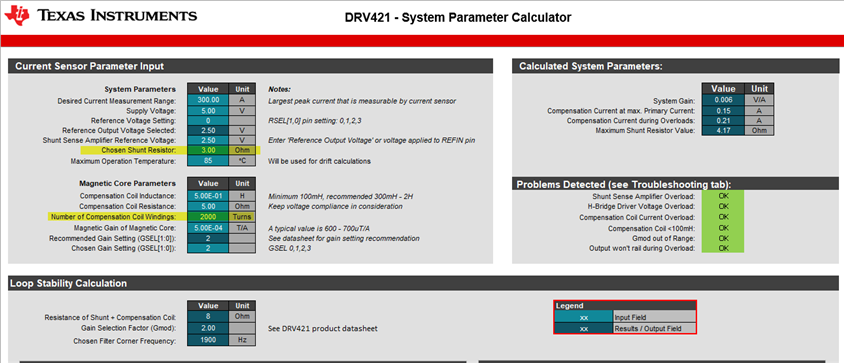
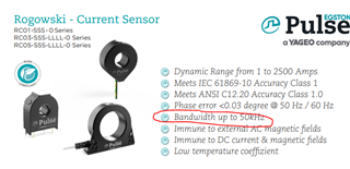
I would like to know any possible solution to measure 300A (peak) - 50khz current waveform for a DC/DC application. 

This shall be able to measure the inductor current from -300A to +300A with a fairly good accuracy. Do we have anything that can be used from the Ti side?

Thanks. 

  • Hello,

    Thank you for your post. Currently we do not have any TMCS devices that can support this request. 

    I would suggest a different part to use for this application: a Hall-Effect Magnetic Sensor such as the DRV421 or the DRV411. 

    Please take a look at this reference design using the DRV411: 100A Closed-Loop Current Sensor Reference Design using Bi-Polar Supplies

    I hope this helps guide your design. 

    Best Regards, 

    Joe

  • Thank you so much for this information. Do you think we can use DRV411 or DRV421 with these type of sensors: HCSP-1BS

    www.mouser.com/.../PIHER_HCSP_1BS_Current_Sensor-3313250.pdf

  • Hello Kanchuka,

    You cannot use this device with the DRV421 or DRV411.

    You will need a magnetic core and compensation coil for the DRV421.

    If you use the DRV411, you will need a magnetic core, compensation winding, and a Symmetric Hall-Element (for example, AKM HW-322, HW-302, or similar).

    This sensor you provided is a complete open-loop sensing solution. Are you trying to make a DRV solution to mimic the performance of the HCSP-1BS?

    Best Regards,

    Joe

  • Hi Joe, I'm trying to mimic the performance of HOYS 400-S-0100. I can not use this sensor as it's heating up the core due to our higher switching frequency. 

    In this case our peak inductor current shall be 400A and switching shall be 100kHz. But still HOYS 400-S-0100 is heating up! Really appreciate your input. 

  • Hello Kanchuka,

    This is a great question and the reason that this is happening is the HOYS 400-S-0100 is an open-loop current sensor and the magnetic core is experiencing rapid changes in magnetic flux as a product of the rapid change in primary current.

    At these higher frequencies paired with an open-loop sensor, eddy currents are higher in magnitude and cause heat generation through an unlaminated magnetic core. These eddy currents generated by the magnetic flux in the opposite direction of the primary conducting current. 

    When using the DRV421 or the DRV411, the flux generated through the core will actually be zeroed out by the compensation coil driven by the DRV devices or the transformer effect described in the datasheet. You can conceptually think of this as a PID controller wanting to remain at 0 Flux. The DRV solutions will reduce large changes in the magnetic flux and heat generation because they want to keep the flux through the magnetic core as close to 0 as possible.

    I hope this makes sense,

    Joe

  • Hi Joe, Sorry for the delay. Do you have recommended core for like 300A (peak) - 50khz for the DRV series?

    Any white paper or application note as the design guideline? Please advice.

  • Hello Kanchuka, 

    Unfortunately we do not have a recommended core but I am hoping the information I am providing below will guide you on your core design.

    I would recommend that you First see this post. This will cover the FEMM simulations so you can view the core and the fields being measured. You can get more real numbers with 3D solvers but for these symmetric simulations I have found that FEMM is good enough. 

    Some of the design challenges are documented here.  Automatically assuming 500µT/A from your magnetic gain you can expect at 8µT offset error from the DRV421 causing an offset error of 16mA for your current measurement.

    The core material is important for a few reasons:

    • The higher the permeability the better magnetic coupling, the better external field rejection, the magnetic gain does not impact as much but you can alter the simulation from the link above to see the changes from that. 
    • The air gap matters more for the gain but you can also see this in simulations.

    Let me know if you have further questions after going through some of the links.

    I hope this helps!

    Best Regards, 

    Joe

  • Hi Joe, 

    Thanks for this information and this is very helpful. My application shall need 300A~400A (peak) @ 50khz sensor and, that's my goal!.

    I'll start working on this and get back to you for further clarifications. Thanks again!

  • Hello Kanchuka, 

    I am glad that you found the link useful. Please respond to this thread for additional support while you continue your design. 

    Best Regards, 

    Joe

  • Hi Joe, Could you please explain me how this DRV421 works? Specifically this compensation coil side! 

    Thanks. 

  • Hello Kanchuka,

    Sure thing.

    For the DRV421, the overall goal of the device is to sense the change in flux and cancel the magnetic field created by the primary conductor through the magnetic core.

    By driving the compensation coil to create an (ideally) equal and opposite magnetic field through the magnetic core, we know the strength of the magnetic field required to drive the magnetic flux through the magnetic core towards 0. We then know the primary current by sensing the shunt resistor in the compensation coil loop.

    This is a high level description and I hope the concept is clear. 

    Best Regards, 

    Joe

  • Hi Joe, this is very helpful and thank you so much. When I'm trying to tune this for 300A peak, it gives me two OVERLOAD flags. Please check the attached snapshot. Any advice?

    I want to find something off the shelf for the Core at this point. 

  • Hi Kanchuka, 

    The nice thing about the compensation loop is you can increase your # of turns to essentially halve the current needed from the H-Bridge driver in the DRV421. This removes the issue with the compensation coil overload.

    The shunt sense amplifier is saturating with your current shunt resistor so I decreased this value to 3 Ohms. This removes the error with your shunt sense amplifier overload. 

    I hope this helps,

    Joe

  • Oh, now I got the point. This is awesome!

    I can use a ferrite core for this application right? Or steel works better with this chip?

    Due to the switching speed, I'm more aligned with a Ferrite core. But we need to cut a slot in the core for the chip and that will be challenging I guess. 

    Thank you so much. 

  • Hello Kanchuka, 

    I am looking into this and I will follow-up shortly. 

    Best Regards, 

    Joe

  • Hello Kanchuka, 

    I want to give you a couple of presentations with FEMM scripts to help you design the core. Using this tool, you can also play with different materials and dimensions. I hate to give you the engineering "it depends" but if you have size constraints for the core then the material you select will be very important.

    So please walk through these presentations and scripts to help you design the core you need. 

    Magnetic Cores No Cutout.pptx

    4274.Build_Magnetic_Core_NoCutout.lua 

    Magnetic Cores with FEMM and LUA.pptx

    5340.Build_Magnetic_Core.lua

    I hope this helps you.

    Best Regards, 

    Joe

  • Hi Joe, This is very useful and I'm going through this material. I have a side question. This is about the TIDA-01063 - https://www.ti.com/lit/ug/tidubv4a/tidubv4a.pdf?ts=1721786875643

    I want to keep this as a back-up option. In there I see the input current frequency is from 45~60Hz. Do you know where this limitation comes from?

    Can we change this circuit to support 100kHz (Input current frequency) range?

    Then I can find the following Rogowski Sensor to go with TIDA-01063...

  • Hello Kanchuka, 

    Thank you for the follow-up. 

    Let me take a look at this and provide you an update on Friday (7/26).

    Thank you for your patience,

    Joe

  • Hello Kanchuka, 

    I am not an expert on that reference design as I only know the DRV devices and solution. 

    If you would like, I can try to track down the experts for that reference design if you prefer that solution.  

    I would also recommend that you reach out to the design team for that product snippet as I am not familiar with that current sensor. 

    I wish I could be more help but I am glad to provide additional support for the DRV421 Slight smile

    Best Regards, 

    Joe

  • Hi Joe, I'm going to try both solutions. So, definitely I'll be  needing your support. 

    Where should I post my questions related to: TIDA-00777 and TIDA-01063. Appreciate your input. 

  • Hi Kanchuka, 

    Let me find similar posts and link them for you by the end of the day. 

    Best Regards, 

    Joe