This thread has been locked.
If you have a related question, please click the "Ask a related question" button in the top right corner. The newly created question will be automatically linked to this question.
Hi,
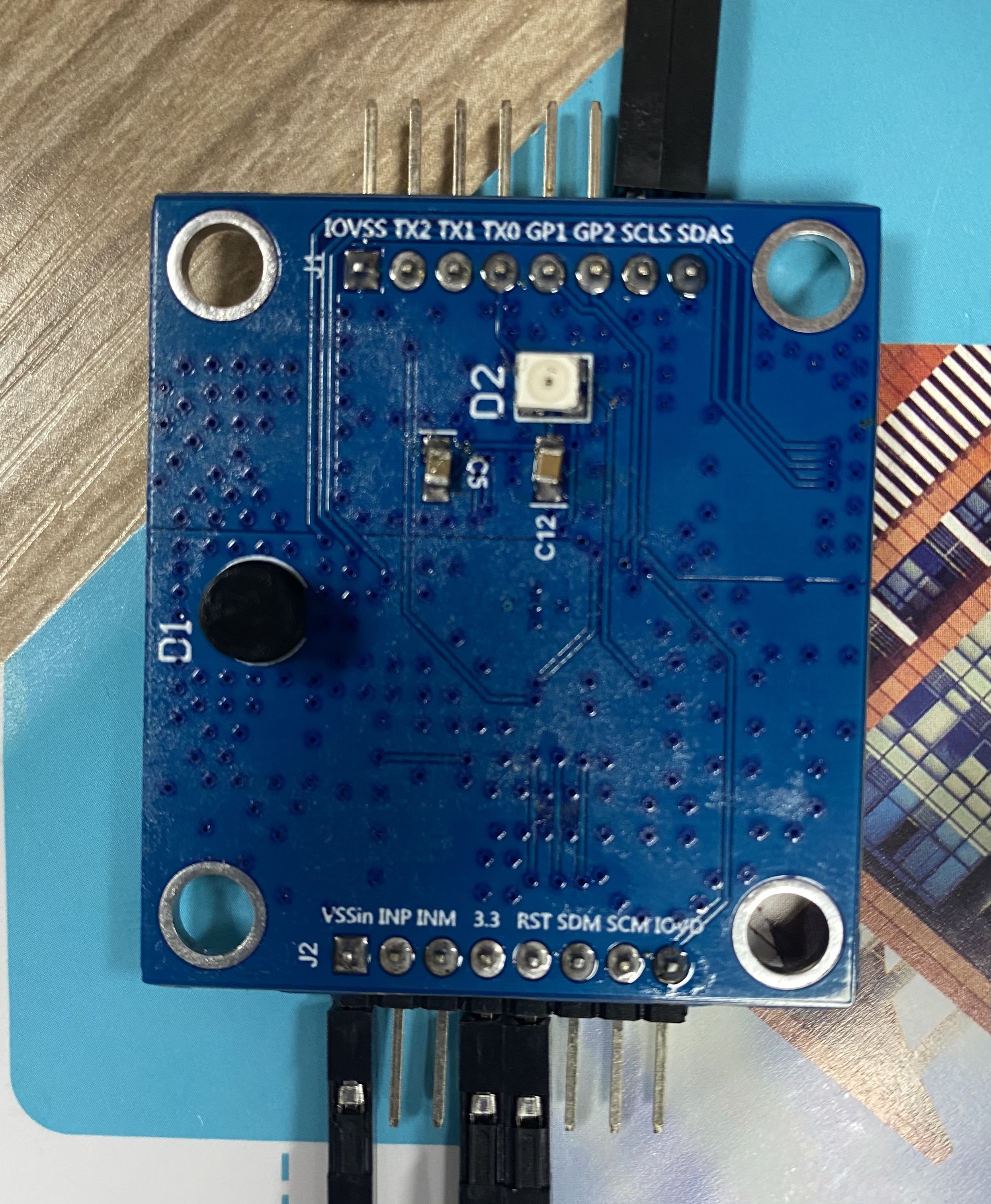
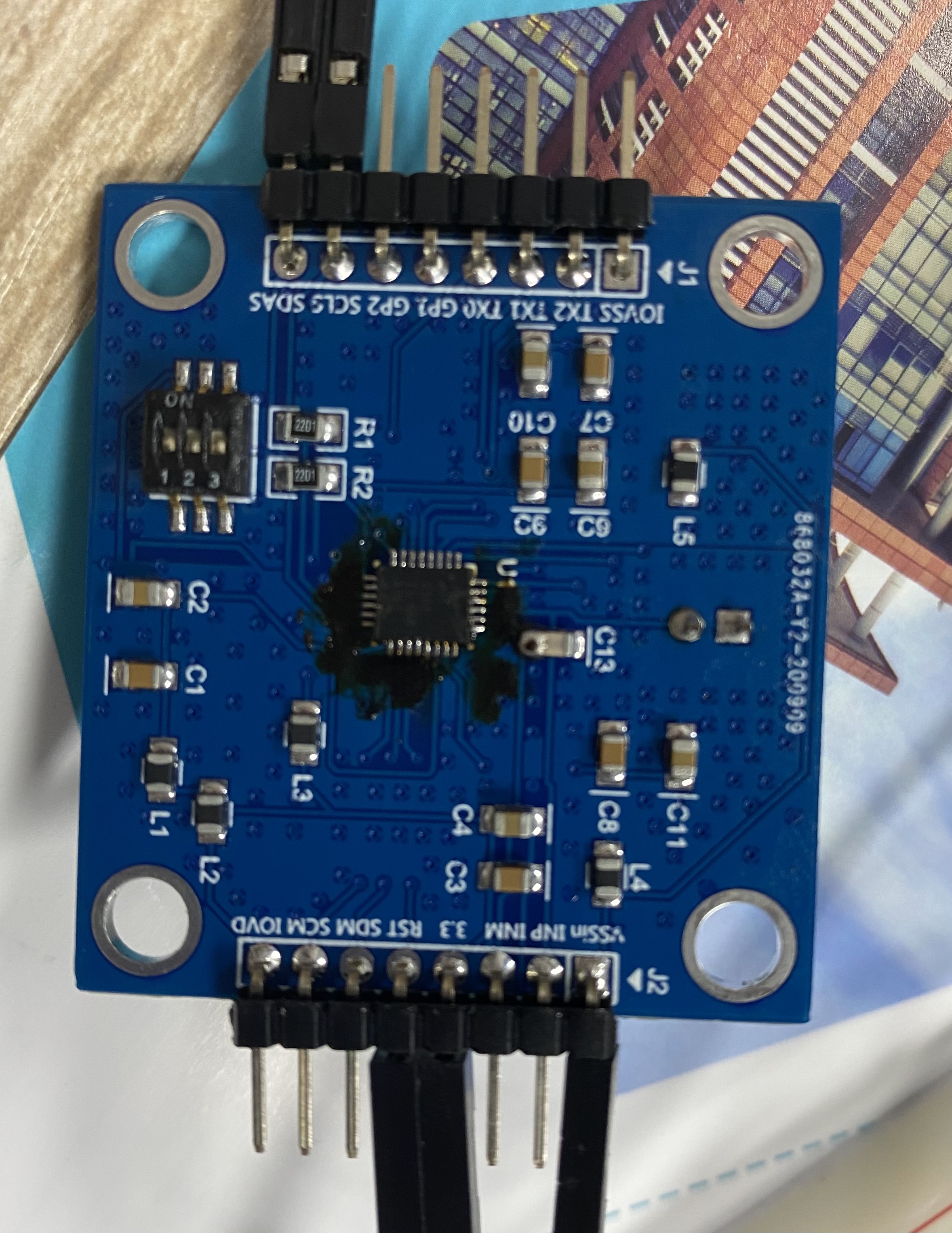
Recently I used the OPT3101 on a custom board and initialized OPT3101 according to the manual.
But I got the following problems(please help support, thank you in advance):
1. I read to the PHASE_OUT(reg 08h[15:0]) and got the value, but no matter shielding with hand or pointing OPT3101 far away, its distance value fluctuates at 3~4 meters;
2. I read to the HDR_MODE(reg 08h[17]) and the value is always 1 which shows OPT3101 has been using ILLUM_DAC_H_TX0, and i think it should be 0 at close range and 1 at long distance;
3. I read to the AMP_OUT(reg 09h[15:0]) and got a very small value less than 1000 that did not meet the requirements.
I want to know if my initialization setting is wrong or I may not be outputting enough optical power from the LED.
So here's how I initialize it: I used i2c-tools to write registers across the I2C bus.
(1) NUM_SUB_FRAMES = 127, NUM_AVG_SUB_FRAMES = 127;
(2) IMAB_MAX_SEL = 14 (200ua);
(3) EN_ADAPTIVE_HDR = 1;
(4) ILLUM_DAC_L_TX0:1.4 * 9, ILLUM_DAC_H_TX0:5.6 * 30;
(5) HDR_THR_HIGH = 27000, HDR_THR_LOW = 1800;
(6) EN_TEMP_CONV = 1;
(7) TG_EN = 1;
(8) INT_XTALK_CALIB = 1→0.
Emitter: https://dammedia.osram.info/media/resource/hires/osram-dam-5340617/SFH%204250S_EN.pdf
Hi,
Are you running calibration on the system before taking data? If so please provide the crosstalk magnitude before and after calibration.
Best,
Alex
Hi Alex,
I ran the illumination crosstalk calibration on the system. Here are some of my data:
Before:
IPHASE_XTALK(reg 3Bh [23:0]):0x00 0x00 0x00
QPHASE_XTALK(reg 3Ch[23:0]):0x00 0x00 0x00
After:
IPHASE_XTALK(reg 3Bh [23:0]):0xff 0xb1 0xe0
QPHASE_XTALK(reg 3Ch[23:0]):0x00 0xce 0x22
Are these values in accordance with the regulations?
Hi,
Can you use the method described here in step 4
https://e2e.ti.com/support/sensors/f/1023/t/727462?-FAQ-OPT3101EVM-Troubleshooting
We want to see residual crosstalk before and after calbration.
What was the method you used for collecting the above? Not sure why before calibration you read 0 - I am thinking you did not set device to collect I and Q data, but linked procedure will work better for this.
Best,
Alex
Hi Alex,
Hi Alex,
I may not set device to collect I and Q data. I masked the photodiode and got some of my data:
Before:
IPHASE_XTALK(reg 3Bh [23:0]):0xff 0xfe 0xe5
QPHASE_XTALK(reg 3Ch[23:0]):0x00 0xae 0x5d
After:
IPHASE_XTALK(reg 3Bh [23:0]):0xff 0x92 0xa6
QPHASE_XTALK(reg 3Ch[23:0]):0x00 057 0x66
Are these values in accordance with the regulations?
Hi,
Could you please measure amplitude from the device as well under the same conditions.
Best,
Alex
Hi Alex,
I measured AMP_OUT(reg 09h[15:0]) and the value was 0x00 0x03.
Best,
Wang
Hi Wang,
This is after calibration, correct? What about before?
Best,
Alex
Hi Alex,
The value of the above was measured after calibration, before: 0x00 0xb8
Let me write down my calibration steps so you can understand.
1. Initialization
Here are the registers I operate on and the values I write in:
reg 9fh: 0x7f 0xf0 0x07
reg 72h: 0xe0 0x00 0x00
reg 2ah: 0x20 0xc9 0x78
reg 29h: 0xc3 0x0f 0x3f
reg 2bh: 0x78 0x69 0x03
reg 2ch: 0x08 0x07 0x00
reg 6eh: 0xe2 0x1e 0x0a
reg 80h: 0x1f 0x4e 0x00
I measured AMP_OUT and got the value:0x00 0xb8
2. I ran the internal crosstalk calibration(wrote reg 2eh:0xb0 0x01 0x30 → 0xa0 0x01 0x03) and measured the following values:
AMP_OUT: 0x00 0x57
IPHASE_OUT: 0xff 0xe8 0x2c
QPHASE_OUT: 0x00 0x83 0xf7
3. Then I masked the photodiode and ran the illumination crosstalk calibration(wrote reg 2eh:0xa0 0x12 0x30 → 0xa0 0x02 0x03):
AMP_OUT: 0x00 0x03
IPHASE_OUT: 0xff 0xad 0xaf
QPHASE_OUT: 0x00 0x40 0x71
Best,
Wang
Hi Wang,
I am looking for amp out after masking the photodiode but before running illum xtalk calibration.
Best,
Alex
Hi Alex,
The amp out after masking the photodiode but before running illum xtalk calibration was 0x00 0x57 ~ 0x00 0x60.
Best,
Wang
Okay, this seems okay. Will follow up here. Can you share a picture of the board as well in the meantime?
Best,
Alex
This is the board we designed ourselves and if it helps you, here is the link to the schematic and PCB diagram:
the google drive:
https://drive.google.com/file/d/1XL516Zt2EmWjcLCDxf5BY-QiEQvUJrzn/view?usp=sharing
Best,
Wang
Hi,
These are both surface mount optics? There are a few potential issues with the board design I am seeing. How are the TX and RX isolated both electrically and optically? I don't see any shielding. Also if SMD and putting on opposite side of the board from the OPT will require vias to route. Both would be expected to result in very high crosstalk. However, when you told me xtalk amplitude it the value looked okay. Can you share photo of how you masked the photodiode in this test. Also are you sure the provided value is correct? Which current setting was the value for? (is it the max 170mA?)
If these all check out then it may be that you just need optical isolation between TX and RX. Have you looked through the system design document online and followed all the guidelines for optics and board design?
Best,
Alex