Part Number: TI-MAGNETIC-SENSE-SIMULATOR
Tool/software:
Where can I find example simulation JSON files for the TI Magnetic Sense Simulator (TIMSS)?
Part Number: TI-MAGNETIC-SENSE-SIMULATOR
Tool/software:
Where can I find collateral that is relevant to the different features in TI Magnetic Sense Simulator (TIMSS)?
Part Number: IWRL6432AOP
Tool/software:
This is an FAQ post, where a TI expert writes the question and response to a common issue that some customers may face during development.
Question: My IWRL6432 device is crashing on the call to rl_fecssRfFactoryCal(). For some reason, it keep rebooting to the demo start like the picture below. I did NOT modify any of the software or hardware, and I'm using a configuration file that never showed any issues before. Why is this happening?

Part Number: MMWAVE-MCUPLUS-SDK
Tool/software:
Q1) How many cycles does CFAR operation take on the HWA?
Comment) The CFAR operation also works in a streaming mode. The number of cycles it would take would be in the order of ACNT * BCNT along with some added latency.
Q2) How is local max used in the OOB demo? / How to configure input and output formatter for Local Max operation:
Comment) A local maxima is performed on the Azimuth FFT samples during the azimuth stage of the doppler processing in both range and doppler dimension to obtain the approximate peak index of the angle FFT. Row-wise as well as column-wise comparison is performed, and "0 1 0 1 0 1 0 1", i.e., a "+" shaped comparison is utilized.
Only the registers in the table below need to be programmed for proper local max functionality – the other bits in the param-set should all be kept 0.

Q3) How and why to use per stage butterfly scaling for FFT operations on the HWA / How to choose scaling configurations on the HWA? / How to check for clipping or saturation in the HWA?
Comment) Some pointers need to be considered when choosing the appropriate scale setting for the data in an actual
use case which will be discussed in this article.
The data bit width of typical radar ADC data is 16 bits, and the internal data bit width of the HWA is 24 bits. This allows for bit growth up to 8 bits without saturation for any of the processing performed which can be controlled by the user. Scaling options available in the HWA with respect to the input and output are as follows:
•Input formatter can scale the input data streamed into the engine.
•Output formatter can scale the output data streamed out of the engine before placing the samples on to the
memory.
•The FFT engine has scaling control over each stage of the butterfly used where the scale of 0.5 can be applied.
•CMULT operations could apply a scaling based on which mode is being used and how the user has configured it.
•It is very important that the user is aware of the scaling applied on the data at any given time of the processing chain in order to understand what level of output to expect, adjust other parameters such as thresholds that heavily relies on the exact scale of the data accordingly.
Need for FFT scaling:
FFT stages to scale based on FFT size:
| FFT Size | Num Stages to scale |
| Less than 256 (2^8) | 0 |
| 256 (2^8) | 0 |
| 512 (2^9) | Last 1 stage |
| 1024 (2^10) | Last 2 stages |
| 2048 (2^11) | Last 3 stages |
When to program the FFT BFLY Scale regs:
Part Number: TMAG5233
Tool/software:
Hall-effect sensors are often the most cost effective option for magnetic switch designs.
When the sampling rate of the Hall-effect sensor is adjusted down, the total active sampling time needed to produce the Hall-effect is reduced and the sensor will spend the majority of the time in a low power mode until ready for the next sample. Devices like TMAG5233 drive the average current down to a minimum by setting the sample rate to as low as 5Hz. This results in a dramatic reduction in power consumption.
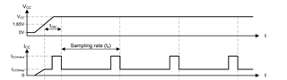
In the image above, we see the normal conversion cycle for TMAG5233, where once the minimum operating Voltage is reached on the supply, the device will periodically become active for a period (tactive), which for TMAG5233 is approximately 26µs.
Based on the sample rate of the device selected, it will remain in sleep mode for a time (ts) until time for the next sample. In the case of the 5Hz variant of TMAG5233 ts is typically about 200ms. This lets the device reach average operating currents as near 0.55µA.
Part Number: TMAG5233
Tool/software:
xMR is a term which generally describes any form of magneto resistive sensor. This includes anisotropic magnetoresistance (AMR), giant magneto resistance (GMR), and tunneling magneto resistance (TMR). Each of these operates under somewhat different mechanisms, but all of these use structures that will vary in resistivity as the angle of the sensed magnetic field changes.
Particularly in the case of GMR and TMR structures, these are built with complex layering of magnetic and non-magnetic materials that are highly specialized. They also include a region which has been magnetized during production that is often referred to as a pinned layer. The magnetization of the pinned layer results with a maximum input magnetic field that if exceeded will re-magnetize this layer and permanently affect the accuracy of the sensor. The complex layer count and this magnetization result in a higher cost manufacturing flow.
The very high magnetic sensitivity and high resistivity of TMR structures tends to allow for low switching thresholds and low operating currents which are both preferred in switching applications. Due to their construction, xMR sensors are often sensitive to a magnetic field component in either the X or Y axis directions.
The high device cost of these sensor materials can make them less desirable in cost sensitive designs. As an alternative, Hall-effect sensors cost advantage make them a practical option when configured correctly. While these devices have higher current while being sampled, it is possible to reduce the sample rate and have the device in a very low power state when idle. Many sensing solutions detect interactions with human-machine interface (HMI) controls, and do not require fast sample rates. Particularly in these cases, Hall-effect sensors like TMAG5233, TMAG5133, and TMAG5134 provide excellent options to consider against an xMR sensor.
| Device | Grade | Sensitivity | Package Options | Average Current (μA) |
| TMAG5233 | Commercial | In-Plane | SOT23-3 (DBV) |
2.7μA (40Hz) 0.55μA (5Hz) |
| DRV5032 | Commercial | Vertical |
SOT23-3 (DBV) TO-92 (LPG) X2SON (DMR) |
5.7μA (80Hz) 1.6μA (20Hz) 0.69μA (5Hz) |
| TMAG5231 | Commercial | Vertical |
SOT23-3 (DBV) X2SON (DMR) |
16μA (216Hz) 2μA (20Hz) 1.3μA (10Hz) |
| TMAG5123 (Q1) | Commercial (Automotive) | In-Plane | SOT23-3 (DBV) | 3.5mA (10kHz) |
Part Number: TMP112
Tool/software:
Please provide example C code for TMP112 temperature sensor.
Part Number: IWRL6432
Tool/software:
If you are not sure if your IWRL6432 is an ES1 or ES2 revision, use the below table to figure out.
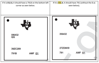
All devices ordered from TI in the future will be ES2. TI no longer produces ES1 devices, so this post only refers to boards already ordered.
Part Number: PGA900
Tool/software:
I have some questions regarding the EVM and software as follows:
Thanks!
Part Number: PGA900
Tool/software:
I have some questions regarding the use of the DAC on the PGA devices as follows:
Thanks!
