This thread has been locked.

If you have a related question, please click the "Ask a related question" button in the top right corner. The newly created question will be automatically linked to this question.

PMP22764: LM51561H

Part Number: PMP22764
Other Parts Discussed in Thread: LM51561H, , LM5155, LM51551

Hi...

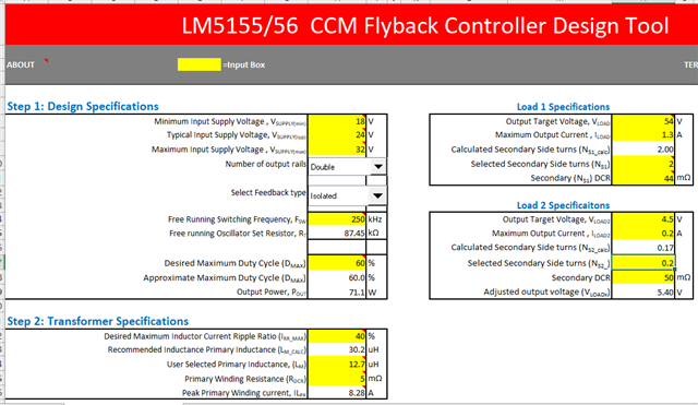
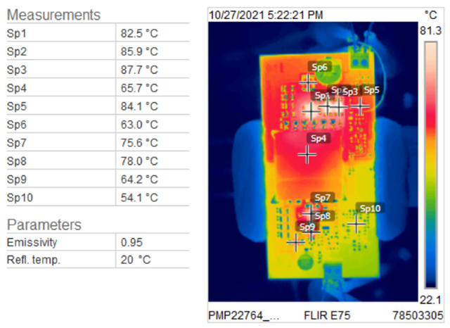
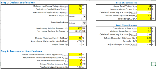
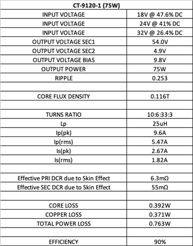
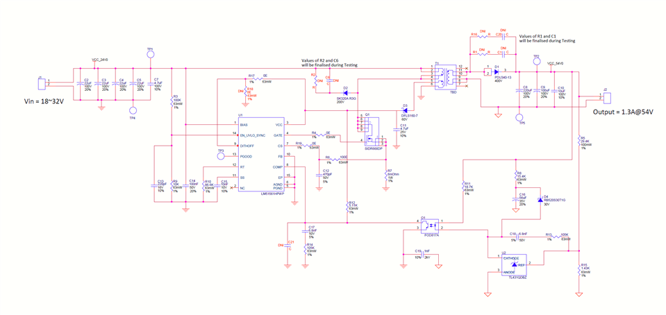
One of my customer is want the PSE solution for 54V/1.25A output. We have recommended LM51561H initially & designed the isolated power supply. We are able to achieve 91 % efficiency but transformer is heating too much & it crosses 100 Deg. C.

We have also taken the ref. of PMP22764, this design is very close to my customer requirement & as per test report it is showing temperature rise close 70 Deg. C which is not matching to our observations.

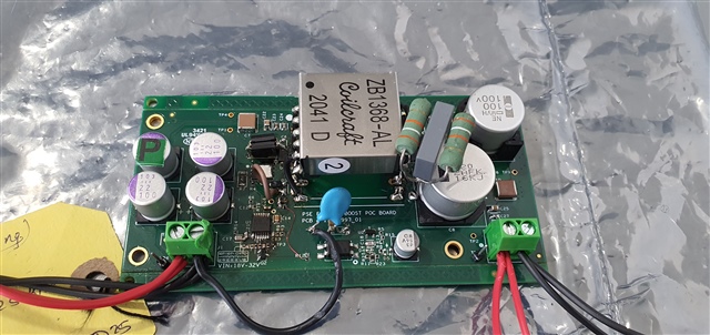
Circuit on PMP22764 & Einfochips are almost similar designs. We have already implemented secondary diode clamp circuit on board which may is not shown schematic. 

As I mentioned electrical evaluation is not an issue but thermal is major challenge. We also see that transformer size (Core ) we have selected is larger than the transformer from ref. design.

What could be the reason for too much heating for transformer? Other components are not hearting that much like snubber, MOSFET, output diode or clamp circuitry.

Mitesh

  • Mitesh,

    Since the temperature of the other components is not affected, I seems like the higher temperature is related to the transformer design.  Can you share the transformer specification?

    I can't tell what the value of the gate drive resistor for Q1 is.  In general you want to turn Q1 on slower and off faster.  It sometimes helps to have a diode in parallel with the gate resistor for fast turn off.

    Thanks,

    David

  • Thanks David for quick response.

    Transformers we have tried with the below specifications.

    Transformer 1:-

    Primary inductance - 8 uH

    Turn Ratio - 1:4 (P:S)

    Core - EFD30

    Trasformer 2:-

    Primary inductance - 4 uH

    Turn Ratio - 1:4 (P:S)

    Core - ETD29

    Transformer 3:- (Yet to Try)

    Primary inductance - 15 uH

    Turn Ratio - 1:4 (P:S)

    Core - EFD30

    We are trying with different transformers to solve this issue. In PMP22764, I believe core used is EFD25 & it seems that 70 watt power is too much to handle by EFD25 & tur ration selected is just 1:2. 

    At present Gate resistance is 0 Ohms & as per the calculations for 250KHz inductance should be ~15uH. 

    Pls. help with your inputs.

    Mitesh

  • Hi David,

    As Mitesh mentioned we are using the LM51561H as isolated boost regulator in our design. I am attaching the LM5155_56_Quick_Start_Calculator along with the flyback transformer datasheet with which we are currently using for testing.

    We are able to load the flyback transformer till 65W and achieve approx. 90% efficiency after adding input and output snubbers. The issue we are facing is that the transformer temperature is going beyond 120°C at 25°C of ambient temperature. Please have a look at the flyback transformer datasheet and share your thoughts on the same? Is transformer is heating due to less primary inductance?

    I have edited the attached LM5155_56_Quick_Start_Calculator sheet as per our requirement. Please have a look and let us know if we need to modify anything into it. We are going to make a flyback Transfromer as per the LM5155_56_Quick_Start_Calculator sheet results.

    Best Regards,

    Aditya Kumar Singh

    LM5155_56_Excel_Quickstart_Calculator_250KHz.xlsx

  • The transformer used on PMP22764 is built on a EFD25 core.  It has a 1:2 turns ratio and operates at about 65% duty cycle with an 18V input.  The primary inductance is 15uH nominal.  Your design should also work with the 1:4 turns ratio, 40% duty cycle and 8uH nominal inductance.  The peak/rms currents will be higher, but a FET and diode can be selected to handle this.  Based on your efficiency and temperatures, the components selected seem to be ok.

    I think the issue may be the way the transformer is wound.  The transformer used on PMP22764 has a split primary (interleaving) to reduce leakage inductance.  Half of the primary is wound on the bobbin, then the secondary, then another identical half primary then the bias winding.  The primary windings are connected in parallel, so it is important they both have the same number of turns.  The maximum leakage inductance is specified at 130nH, which is less than 1% of the 15uH primary inductance.  I don't see the leakage inductance specified on your transformer, but based on the SRF of 750kHz typical, I would say it is much higher.  I am thinking your transformer does not have the interleaving.  Also, with the 1:4 turns ratio and no interleaving, your transformer probably has much higher proximity losses since the secondary is most likely 4 layers versus two layers for a 1:2 transformer.  The proximity losses are caused by currents induced multiple layer windings that dissipate power higher than the actual delivered power.  Interleaving should reduce the proximity losses significantly.

    Check to see how your transformer is wound.  If the primary is not interleaved, then you should have a new one wound that is interleaved.  The leakage inductance should also be specified.  Usually something less than 1-2% of the primary inductance will result in good performance without excessive power loss.  Another item is to make sure all of the windings span the complete bobbin width.  This will also help reduce the leakage inductance.  It helps to use multiple strands of smaller gauge wire wound in parallel to fill the bobbin width.

    Thanks,

    David

  • When you measure the transformer temperature, is it the windings, the core or both that are getting hot?  Do you see a hot spot in the middle of the windings that gets cooler as you move to the outer edges of the transformer?

    Thanks,

    David

  • Hi David,

    Thanks for your quick response.

    We measured the leakage inductance of the 65W transformer and it is 0.514uH which is around 6.4%. 

    Ok, we will wound the transformer as per your suggestion with ETD29 core and make sure that the new transformer should have leakage inductance less than 1%. We are also planning to go with 1:2 turns ratio instead of 1:4 since as per your suggestion it will reduce the proximity losses.

    Changing the turns ratio will change the duty cycle. For 1:4 and 1:2 turns ratio the duty cycle is approximately 43% and 60% respectively. Can you please share your opinion on how duty cycle will effect the thermal performance and efficiency of the design. What duty cycle you would recommend for our design?

    Also, I calculated the primary inductance using the LM5155_56_Quick_Start_Calculator and got 30.2uH for 1:2 turns ratio. Please see the below image-

    Inductance is directly proportional to number of turns so 30.2uH will lead to a higher number of turns which might not fit into the ETD29 bobbin. Shall we go with 15uH of primary inductance since it worked into PMP22764 reference design having 1:2 turns ratio or go with 30.2uH ( calculated value from LM5155_56_Quick_Start_Calculator sheet) or some mid value between 15uH and 30.2uH. Please suggest.

    Best Regards,

    Aditya Kumar Singh

  • Since the converter is operating in continuous conduction mode, the turns ratio used will determine the maximum duty cycle at low input voltage.  Using a 1:2 turns ratio will result in about 60% max duty cycle at 18V input.  The higher duty cycle will result in the output rectifier being on for a shorter period of time and the primary FET being on for a longer period of time.  This should help increase the efficiency since the diode has a relatively large forward voltage drop and will dissipate more power if on longer.

    The primary inductance will determine the peak to peak ripple current.  I had to use the lower 15uH inductance on the PMP22764 design so that I could fit the xfmr on the EFD25 core.  More inductance will require a larger core.  The 15uH inductance on the EDF25 core was a good balance for these design parameters.  The ETD29 has about 50% more core area and double the winding area, so increasing the inductance may be possible.  You need to work with your magnetics vendor to adjust the inductance versus operating flux density.

    Are you familiar with the Power Stage Designer Tool available on our website?  You can take the values calculated using the LM5155/56 spreadsheet and enter them into the tool.  You can then view the component waveforms for the major power stage components.  You can vary the input voltage and load current and see the changes.  You can also vary the inductance to see how it affects the waveforms.  There are also tools for various circuit calculations.

    https://www.ti.com/tool/POWERSTAGE-DESIGNER?keyMatch=POWER%20STAGE%20DESIGNER%20TOOL

    Thanks,

    David

  • Hi David,

    Thanks for your quick reply.

    As I can see from the test report of PMP22764, the transformer temperature is approximately 67 degree Celsius at room temperature. Please refer to below image-

    We were not able to find the load condition for thermal test. Is it performed @70W load for min. 2~3 hours of bench testing? Please share your thermal experience with the ZB1368-AL transformer.

    Also, we would need to achieve similar thermal performance in our design and for that we have planned to make the Flyback transformer with below parameters-

    Please share your thoughts on the same.

    Best Regards,

    Aditya Kumar Singh

  • The conditions for the thermal plot are 24V input and 70W load.  The board is clamped to a vise sitting on the lab bench.  The ambient temperature is approximately 20C.  The board temperature stabilized in 15-20 minutes, then the measurement was taken.

    I did not notice earlier that the switching frequency you selected is 125kHz.  That is why the inductance is double that of the PMP22764 design, which operates at 250kHz.  You may gain 1-2% in efficiency switching at the lower frequency.

    Thanks,

    David

  • Hello David,

    We have received ZB1368-AL used in PMP22764 design and installed into our board which is based on LM51561H. Observations are as below,

    • At 250Khz frequency of operation - we could load it upto 42W only. After that it is shutting down. efficiency =85%
    • At 125Khz frequency of operation - it goes upto 55W and shutting down. It is also observed that power supply does not start at 55W again and can go upto 45W. It looks after heating it is tripping. effi =87%

    Could you please share your thought on this ? What could be the issue ? We have maximum Power requirement is 65W and based on that we went with PMP22764 like design. Request you to help us on this. Below is the image of the device. 

    Do you think, is it because of different device LM51551 vs LM51561H ?

    Testing is in progress, we will share more thermal data. 

    Regards,

    Mahesh


  • At 250kHz it sounds like the current limit is tripping.  What is the value of the current sense resistor?  PMP22764 uses a 0.008 ohm sense resistor.  Also, what are the values of the two resistors in series between the current sense resistor and the CS pin?  There is a slope compensation current (30uA typical) flowing through these that will subtract from the CS trip point.

    The transformer is designed for 250kHz and is probably saturating when operated at 125kHz.  It will not work at 125kHz and maximum load.  The only difference between the 51 and 61H is the 61H has dithering and a different package.

    Thanks,

    David

  • Please find the attached schematics. we are using 6mohm of resistor. We are using 0E and 100ohm at CS. LM51561H_POC-BBW73Z2.pdf

  • The loop compensation values and configuration are not correct.  Please modify per the PMP22764 schematic attached.

    PMP22764B(001)_Sch.PDF

    Thanks,

    David

  • Hello David,

    We tried the compensation value as your have but in our case we are getting abnormal shutdown of the device. We are still looking into it.

    Anyhow, with our design we have designed below transformer . This transformer has gap reduced between core and copper as per the suggestion.

    With this transformer, we have observed that, it is shutting down at 24W load only. We are operating at 125Khz of frequency. We have observed the upto 22-23W load, gate waveform is okay but after that, abnormal behavior observed.  Below are the waveform.Due to higher inductance design always operate in CCM mode. Is it due to higher inductance and not because of that not able to achieve required primary peak current ? Device also recovers as, on reducing the load without power cycle.  Can you please look into it and share you some suggestion ?