CC1310: jtag issue, device identified in SmartRF once only

Part Number: CC1310

hi,

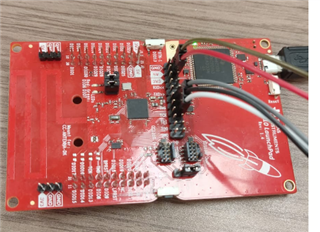
we are connecting our custom board with CC1310  to launchXL in order to program it.

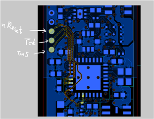
  • we use VDD, GNS, TCK, TMS and Reset pins.
  • on Reset pin , in our custom board, we have 100Kohm pull up, and 100nF cap to gnd
  • Vddr measured ~1.67V

the issue is that SmartRF and Flash Programmer identify the CC1310 once, and when we press "refresh" it becomes non-identified. 

once we power-cycle the board it becomes identified again for one time, and so on.

when I used CCS and tested JTAG connection we get some issue: at first try the test succeedes, and the next time on it doesn't.

we lowered the JTAG clock to 100KHz and problem is solved (JTAG test passes each try)

can you help with this issue? 

thanks

Dan

  • BTW, 

    when JTAG test fails, I get following report:

    [Start: Texas Instruments XDS110 USB Debug Probe_0]

    Execute the command:

    %ccs_base%/common/uscif/dbgjtag -f %boarddatafile% -rv -o -S integrity

    [Result]

    -----[Print the board config pathname(s)]------------------------------------

    C:\Users\dano\AppData\Local\TEXASI~1\CCS\

        ccs1260\0\0\BrdDat\testBoard.dat

    -----[Print the reset-command software log-file]-----------------------------

    This utility has selected a 100/110/510 class product.

    This utility will load the adapter 'jioxds110.dll'.

    The library build date was 'Dec  6 2023'.

    The library build time was '17:33:10'.

    The library package version is '12.6.0.00029'.

    The library component version is '35.35.0.0'.

    The controller does not use a programmable FPGA.

    The controller has a version number of '5' (0x00000005).

    The controller has an insertion length of '0' (0x00000000).

    This utility will attempt to reset the controller.

    This utility has successfully reset the controller.

    -----[Print the reset-command hardware log-file]-----------------------------

    The scan-path will be reset by toggling the JTAG TRST signal.

    The controller is the XDS110 with USB interface.

    The link from controller to target is direct (without cable).

    The software is configured for XDS110 features.

    The controller cannot monitor the value on the EMU[0] pin.

    The controller cannot monitor the value on the EMU[1] pin.

    The controller cannot control the timing on output pins.

    The controller cannot control the timing on input pins.

    The scan-path link-delay has been set to exactly '0' (0x0000).

    An error occurred while hard opening the controller.

    -----[An error has occurred and this utility has aborted]--------------------

    This error is generated by TI's USCIF driver or utilities.

    The value is '-242' (0xffffff0e).

    The title is 'SC_ERR_ROUTER_ACCESS_SUBPATH'.

    The explanation is:

    A router subpath could not be accessed.

    The board configuration file is probably incorrect.

    [End: Texas Instruments XDS110 USB Debug Probe_0]

  • Hi Dan,

    Could this be due to noise on the TCK-pin? See Section 5.4 of the SWCU117 (CC13x0, CC26x0 SimpleLink Wireless MCU Technical Reference Manual): https://www.ti.com/lit/swcu117

    Could you try the following first to try and isolate the root cause:

    Please note that there will be limited support until next week due to the Easter break.

    Regards,

    Zack

  • Hi Dan,

    Just to double-check as well: If you connect the LAUNCHXL-CC1310 only (with the jumpers set for this), does it work as intended, i.e. the CC1310 is identified and behaves as expected? This is just a quick test to check that your LAUNCHXL-CC1310 is working correctly.

    You may also find this documentation useful: https://software-dl.ti.com/ccs/esd/documents/ccs_debugging_jtag_connectivity_issues.html#a-router-subpath-cannot-be-accessed 

    A router subpath cannot be accessed

    This error is caused by the inability of the JTAG debugger to access any of the subpaths of either the ICEPICK or the DAP. This is usually caused by either a hardware failure on the board or invalid code on the subcore that causes it to reset itself continuously. This is very similar in nature to the error Cannot access the DAP above but at a higher level.

    If this error is originated in hardware (custom hardware or faulty board or connections), please check this e2e forum thread. Also, power supply problems can lead to this issue as reported in this e2e forum thread.

    If this error is originated in software, it can be either due to a problem with the configuration file (as mentioned in this e2e forum thread or potentially be recovered by accessing the DAP directly and trying to either reset the offending core, lock it or mass erase its flash memory.

    If using a microcontroller, to mass erase its Flash memory please check step 9 of the section Troubleshooting the connect phase above.


        Error connecting to the target:
        (Error -242 @ 0x0)
        A router subpath could not be accessed.
        The board configuration file is probably incorrect.

    Regards,

    Zack

  • hi

    thanks for quick reply..

    1. when I connect the LaunchXL to the on board CC1310 it works fine, even with not-so-short jumper cables..

    2. attached is picture of the LaunchXL, so you can see the state of jumpers when I want to program my custom board. is it OK?

    3. I tried putting 22pF cap between the TCK line to GND, on the LaunchXL side, and it didn't help

    4. attached is pictur from layout. maybe the issue is due to TMS, CLK, nReset lines being very close to each other (crosstalk)?

    5. how can I Check if the Halt-in-Boot (HIB) flag is set?