This thread has been locked.

If you have a related question, please click the "Ask a related question" button in the top right corner. The newly created question will be automatically linked to this question.

CC1190: 2nd harmonic above 30dB

Part Number: CC1190
Other Parts Discussed in Thread: LAUNCHXL-CC13-90US, LAUNCHXL-CC13-90EU, CC1310, CC1120

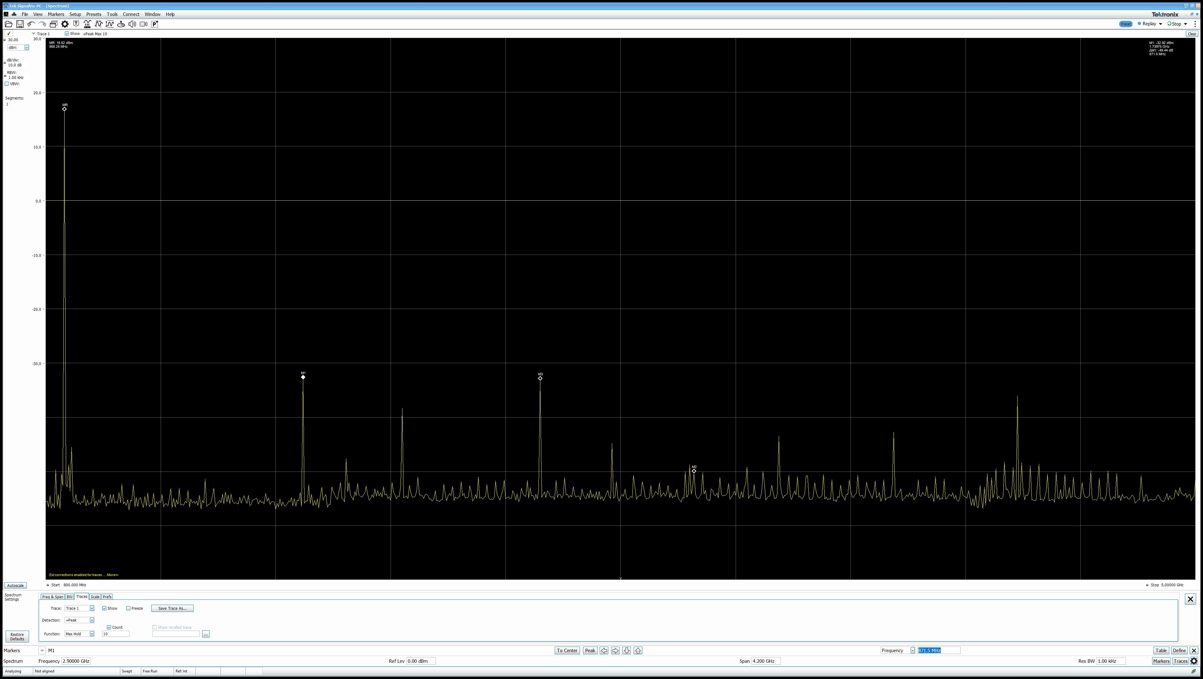
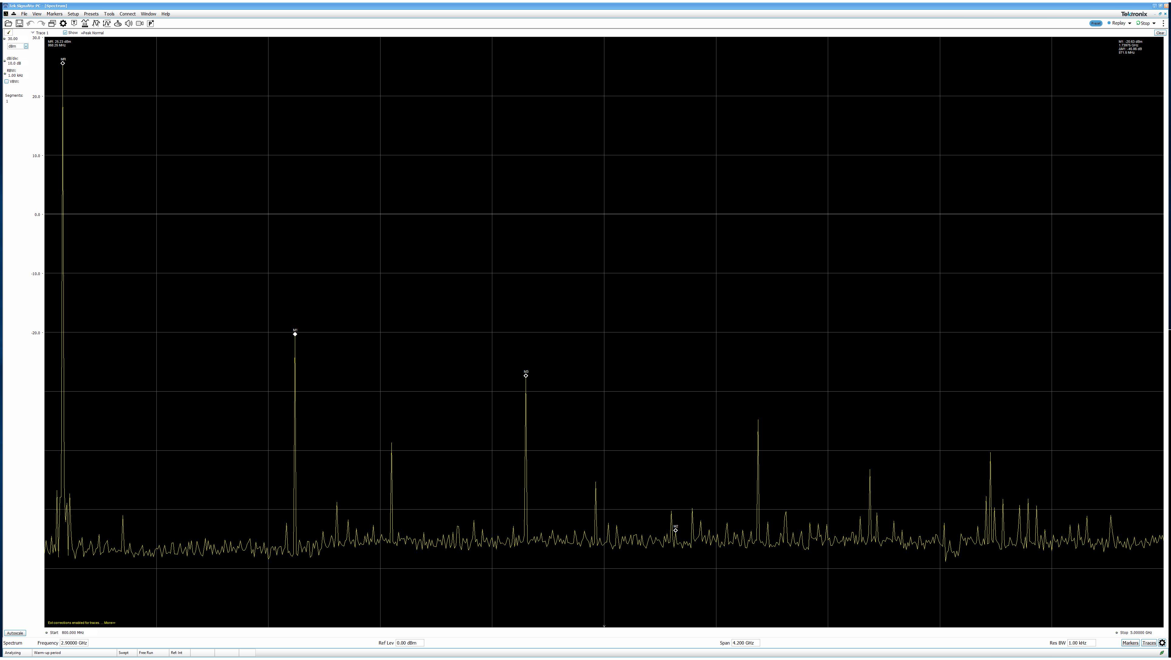
I have a design using a CC1190 and I am experiencing a 2nd harmonic above -30db and failing EU regulations. I have attached 2 plots, and at full power the the 2nd harmonic is -20dB. How can I reduce the harmonic?

  • Hello George,

    Is this for the 915Mhz band or 868MHz band?

    Did you follow the matching reference design (LAUNCHXL-CC13-90EU) or (LAUNCHXL-CC13-90US) both schematic and layout?

    Have you matched the antenna to 50 Ohm?

    There is a thread that discuss relevant topics that worth reading: 

    https://e2e.ti.com/support/wireless-connectivity/sub-1-ghz/f/156/p/735681/2719101#2719101

  • At 915MHz the board is ok, as the harmonic is relative to the fundamental.

    At 868 the regulations are an absolute -30dB (57db down from the fundamental) so it is much tougher to pass.

    I have followed the reference design for the CC1190 and there is no reference design for the NRF9E5 and CC1190 combo.

    The antenna is matched.

    I tried powering the PA separately from the NRF9E5, with a USB supply for the transceiver and a separate 3.3V bench supply for the 1190 but I still see the harmonic.

    The PA has a separate thick connections on Layer 3 of the 4 layer board, and the power layer is removed under the PA

    I will look at the SAW filter grounding, I see some articles say to remove the ground plane below and retreat the ground plane on the top layer and connect the output grounds with a via as close as possible to the SAW. Is that best?

    Regards

    George

  • Hello George,

    Which SAW filter did you use?

  • For 868MHz B39871B3725U410 and 915MHz B39921B3588U410 both from Qualcomm

    regards

    George

  • Hello George,

    The SAW filter should indeed help reducing the harmonics.

    1. Can you measure the output power and harmonics:

    • Before the SAW filter.
    • After the SAW filter.
    • At SMA (after CC1190 filtering).

    2. Would switching main SoC Radio to CC1310 or CC1120 be an option? Then we could compare on our own ref designs.

    3. Have you gotten a design review (schematic and layout)?

  • I will attached the schematic and gerbers, unfortunately the client uses a Nordic protocol, so I can't change from the nrf9E5.

    To try and improve it I have done the following

    1) retreat the copper on the top layer from around the SAW filter

    2) Separate the power to the NRF9E5 and the CC1190 and star close to the on off switch

    3) keep the power plane away from the RF sections

    4) retreat the power plane away from the edge of the board, replace with additional 0V fill and increase the ground stitching.

    Schematic and gerber files attached.KT200R10.pdfK200R10_2020-10-01.zip

  • Hello George,

    Did you measure before and after the SAW filter?

    Schematic:

    • C38 should be 220 pF instead of 22pF.
    • C27 (2.7pF) and L25 (2.7nH) form a notch to filter the second harmonic. In the ref design these have values 2.4 pF and 2.4nH. It might not make much of a difference, but its worth looking into.

    Ill look at the layout next.

    Are these files based on the new spin?

  • I have made a couple of CC1190 based reference designs and my experience is that the two notches (C27/ L25, L11/ C35) have to be adjusted when a new layout is done, see 5.2 in https://www.ti.com/lit/an/swra542/swra542.pdf

    I would recommend to do measurements to verify that the notches are actually placed at the 2. harmonic.