This thread has been locked.

If you have a related question, please click the "Ask a related question" button in the top right corner. The newly created question will be automatically linked to this question.

TUSB2046B "USB not recognized"

Other Parts Discussed in Thread: TUSB2046B, TPS2041B, TPS2041

8473.TI TUSB HUB.pdf

Hi,

I am using the TUSB2046B 4 port hub.

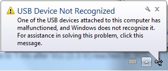
Getting the message "USB not recognized".

I am using 2 of the ports.  Please see 5 page schematics attached.

I have the 1.5K pull up on DP0 fitted with the 1 x 27pF cap to GND for DP0 and DM0.

I have 15K pull downs on DP1, DM1, DP3, DM1 and also the 27pF caps to GND for all these.

Please assist

  • Hello Neil,

       I've reviewed your schematic and I have the following notations for you (I am assuming the the system does not recognize the TUSB2046B, please clarify if my assumption is wrong):

    1. Remember that the RESET must be asserted at power up with a pulse width between 100 μs and 1 ms is recommended after 3.3-V VCC reaches its 90% and the clock signal has to be active during the last 60 μs of the reset window. Since your application is bus powered, the previous reset sequence must occur just after attach the upstream port.
    2. Please attach the 3.3V generation, to validate the bus powered feature.

    Best regards,

    Diego.

  • Hello,

    Here are my comments:

        1. As Diego said the TUSB2046B requires a reset pulse of between 100 us to 1 ms after Vcc (3.3-V) reaches its 90% (see below the power-up sequence).


        2.The DP and DM signals of the unused port should be tied to ground with 15K resistors like the pull-downs used on the active ports.

        3.TI recommends to use a 30-ppm crystal, it is acceptable to use a 50-ppm crystal with a load capacitance of 20 pF. The formula to approximate the value of load capacitors used is:
            CL = ((C1 × C2) / (C1 + C2)) + Cstray.
    Cstray is the stray capacitance in the circuit, typically 2 pF to 5 pF. When CL = 20 pF, C1 and C2 are approximately 27 pF to 33 pF each.

    Regards.

  • Hi Diego,

    It gives the message as per attached .jpg.  The PC still picks up the FTDI device via the hub though and the FTDI communication works fine.

    I have the 2K pull up resistor and 100nF capacitor to ground on the reset line.  My understanding is that this causes the desired delay on Reset line with power up ?

    Power supply attached.5125.Schematic Prints.pdf

    Regards

    Neil

  • Hi Joel,

    Thanks for the reply.

    1. I am using the 2K pull up and 100nF capacitor to ground as I think you guys recommend on the forums. ? Will this suffice ?

    2. I do not have pull downs on the non used pins.  Will try that.

    3. I am using a 30ppm crystal with recommended 8pF caps for that crystal.

    As mentioned to Diego the message appears but the FTDI device still works via the USB hub.

    Regards

    Neil

  • Hi Diego and Joel,

    Thanks for the help.

    Placing 15K pull downs on DM2, DP2 and DM4, DP4 (the two unused ports) seems to do the trick.

    I have tested it on one PCB only.

    Neil

  • Hi Diego and Joel,


    I am having another problem.

    On one of the downstream ports I am connecting an Android cell phone.

    Getting the following error on the windows side:

    Windows has stopped this device because it has reported problems. (Code 43)

    Schematics etc previously attached.

    Neil

  • Hi Diego and Joel,


    It seems both problems I am having is the same and the problem is thus still the original one.

    "USB Device not recognized..." and when I look under device manager -> Universal Serial Bus Controllers it shows the hub as "Unknown Device" with error "Windows has stopped this device because it has reported problems. (Code 43)".


    I have the following:

    1. Using ports 1 and 3. Not using ports 2 and 4.

    2. 15K pull downs to ground for all downstream ports used and not used: DP2 and DM2, DP4 and DM4, DP1 and DM1,        DP3 and DM3

    3. From reset line a 2K pull up to 3V3, and from reset line a 100nF pull down to ground.

    4. I have 10K pull ups to 3V3 on:

        OVRCUR1, OVRCUR2, OVRCUR3, OVRCUR4.

    This is getting urgent. Please help!.

    Neil

  • Hello,

    A few thoughts:

    If the FTDI device is working then the Hub is working fine too.

    Which one is the unknown device? The TUSB2046B or the android ?

    Change R49 to 20K.

    Check the physical connection of DP0 and DM0.

    Is one of the OVERCUR# terminals being asserted?

    Does the android device works if you disconnect the FTDI? (I am looking for a current budget issue)

    Is the android device full-speed capable?

    Regards.

  • Hello Neil,

    Are the XTAL1 and XTAL2 receiving a 6MHz signal ?

    Regards. 

  • Hi,

    The only resistors on upstream and downstream ports are populated as per my last explanation not as per schematics.

    What would be the two different cases for full speed and normal speed downstream devices ?

    Neil

  • The FTDI chip has compatibility with full speed USB.

    I can pick up the FTDI and have communication to it.

    However fot the downstream port 3 connected to tablet it complains:

    Windows has stopped this device because it has reported problems. (Code 43)

  • Is the Tablet a high-power device?

    Is the tablet getting 5V on VBUS?

    Can you ship one of your platforms for debug?

    Is the OVRCUR# signal being asserted?

    Uninstall and re-install the tablet driver.

    Does it happens on several systems?

    Regards.

  • 7673.01.pdf

    8802.02.pdf

    5164.03.pdf

    6840.04.pdf

    5282.05.pdf

    Hi,

    I have attached updated schematics of the current state of the hardware.

    This shows all voltage levels etc.  Also used and unused ports. Pullups and pull downs etc populated and those not populated.

    DNF = Do Not Fit.  Marked in red next to some components.  These components are not populted.

    Yes I have tried it on several PCB's same thing.  Also that is why I do not suspect the crystal (but will still check this).

    Will check if OVRCUR is being asserted. Is this asserted on all ports used and while in use ?

    Have tried uninstalling the driver.  Using my Android phone not a tablet but also tried different android phones.

    It seems the FTDI is picked up fine and works fine on its own but as soon as I plug in the Android the dreaded windows error message appear for the USB device.

    The tablet gets 5V.

    We can ship a PCB for debug but would like to find the problem rather very urgent.  We have a client needing a working unit by tomorrow.

    Please look at schematics carefully and give any ideas ?

    What number can I phone you on ?

    Neil

  • I have a diode blocking current from the tablet.  Only supply possible is from the upstream port.

  • Hi,

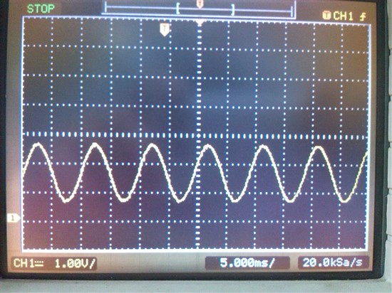
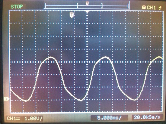
    Have measured the 6MHz crystal for TUSB:

    XTAL1:

    XTAL2

    Does the voltage levels etc look good ?

    Neil

  • OVRCUR1, OVRCUR2, OVRCUR3, OVRCUR4 are all asserted. 

  • Tried replacing R49 from 2K to 20K (resistor on reset line). Still no luck.


    Out of ideas now...

  • Tested connectivity on all upstream and downstream DP and DM lines.  All good...

  • Are the OVRCUR# asserted-low ? This is not good, are the OVRCUR# asserted-low only after you connect the tablet? If so, then the tablet is drawing more than 500mA.

    Regards.

  • OVRCUR1, OVRCUR2, OVRCUR3, OVRCUR4 are all high. That ok ?
  • Hi Guys,

    Please respond.  I need a solution for this problem!

    Neil

  • Hi Neil,

    Could you provide some trace captures using a USB protocol analyzer between the host and the TUSB2046B?

    Regards.

  • Hi,

    I doubt it is a problem with the PCB track layout.

    Reason I doubt it is that when in stead of connecting the Android phone to the downstream 1 port I connect the same FTDI circuitry running at 115200 baud it does not pick up the FTDI driver etc.

    I pick up the TUSB hub driver no problem.  Also the origional FTDI driver connected to downstream 3 port is picked up and working.  It is only the downstream 1 port device (either Android phone or another FTDI device) that is not picked up.

    What are you guys thinking ?

    Regards 

  • Hi Guys,

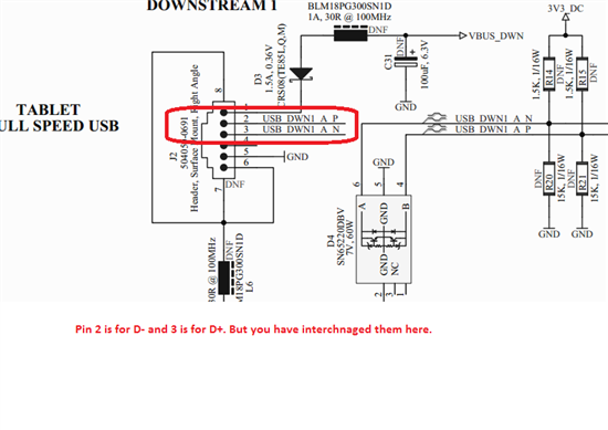
    I swapped around the D+ and D- lines for the downstream 3 port when compared to the same connector on the upstream port.

    My apologies!

    When connecting the second FTDI device to the downstream 3 port all works.

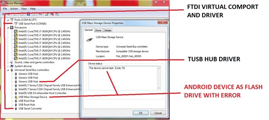
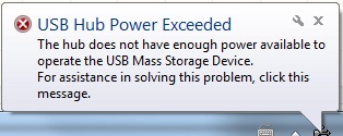
    But when I connect the Android phone I still have a problem.  On the android phone I at least get the option now to select if I want to use it as a flash drive etc but the driver still seem to have a problem.

    See picture:

    I have also checked all OVRCUR lines.  OVRCUR1, OVRCUR2, OVRCUR3, OVRCUR4 are all high before I insert the Android device and after I have inserted the Android device they are still all high.


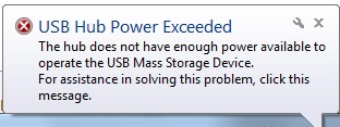
    I also see these complaints and errors when I insert the Android device:

    Even when I disconnect the 5V line from the USB upstream port and supply 5V power externally both the "Power exceed" error remains and the "Device can perform faster" warning stays. The driver problem also still remains.

    I then disconnected power to the downstream 3 device port (Android device) and supplied 5V externally.

    Also measuring the current supply from USP upstream port. The power supplied to all circuitry from USB upstream port is only 45mA.  Still get the power exceed error etc.

    Is there something I can try like pull ups rather than 15K pull downs on DM3 and DP3 before looking at PCB layout etc ?

    Regards

    Neil 

  • Hi,

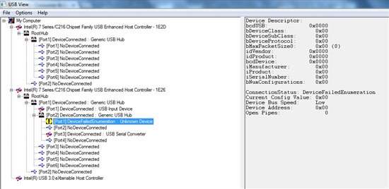
    Download the usbview (7411.usbview.zip) utility to get more information about the device. Select the item (Android device) in the left window will allow its descriptors to be read in the right window. Could you attach some screen captures? 

    Could you change to Self-powered mode? Connect an external power supply and the BUSPWR input to GND.


    Regards.

  • Hi,

    I cannot download the utility (7411.usbview.zip), the link gives an error.

    Screenshots of what? please see my last post. I have updated it and there are some screenshots.

    Will try pulling BUSPWR to GND and power externally.


  • Hi,

    Ok it works if I power it completely externally and pull BUSPWR to GND.

    This is not an option for me.  What do you suggest ?

    Neil

  • Hi,

    I have no added another TPS2041B 500mA current limit switch in front of the entire circuit.

    In other words the 5V line coming in from the upstream port and supplying all current goes through this current limiting switch and I still get the error as in picture:

    I have also tried leaving the extra switch in, take the phone battery out and put the phone in airplane mode. still get the error below:

  • Hi,

    When the hub is configured as bus-powered mode the downstream ports cannot be high-power devices (because they will be drawing more than 100mA). The device sends a configuration descriptor to indicate the amount of power required. Usbview utility will allow us to read the maximum power consumption of the device.

    4431.7411.usbview.zip

    Regards.

  • Hi,

    My understanding was that the TPS2041 switch and the TUSB hub limits the current to the devices to 100mA on each downstream port ?
    From the looks of it the TPS2041 does not even limit the current to 500mA if I place it right in front of all circuitry.

  • So I guess the problem is that the Android phone draws more than 500mA current and the hub then complains.

    Originally I have two TPS2041 switches.  One for each downstream hub (the other two downstream hubs are not used).

    Have you got a replacement TPS type switch you can recommend that is pin compatible with TPS2041 but limits at about 250mA as well as supply 250mA current continuously ?

    Perhaps it will work if I limit Downstream 1 (Android device) to 250mA and Downstream 3 to 100mA with a TPS type current limit switch.

  • Hi,

    Each downstream port from a bus-powered hub is only required to provide 100mA if you plug a 500mA device into a bus-powered hub, the host will not configure it. Even if the device is not actually drawing more than 500mA it sends a configuration descriptor to indicate the amount of power required. 

    Regards

  • Why can I then plug my Android phone into another USB hub also drawing power from a single USB port and it works fine ?

    What do you recommend I do then ?

    Will it work to use one of the TI current limiting switches similar to TPS2041B limiting current to downstream port to 100mA?

  • Hello,

    Could you supply power to the hub via the VBUS and connect the BUSPWR input to GND?

    Regards.

  • I have tried connecting pins 3, 8, 25 and 26 of the hub connected to 5V from bus and related pull up resistors to 5V. With BUSPWR still connected to 3.3V.

    It does not recognize the USB device.

    Have you got a full reference design schematic for bus powered mode as you have for self powered mode ? 2843.TUSB2046 - Plain Self Power.pdf

    I noticed that I have pin 6 of the TUSB2046B (EEDATA/GANGED) connected to GND and not 3.3V.  Will this cause this cause the current problem ?

  • Can you guys please respond to my last post ?

    Can you please give me a number that I can phone you on or e-mail me the number:

    neil.badenhorst@poynting.co.za

  • Hi,

    Please have a look at following. Hope this will help.

    Warm Regards,

    Bhaumik

  • Hi,

    Yes I am aware of that.

    It works fine now that I have used "Self-Power"mode.  Pulling BUSPWR to GND and not to 3V3.

    I understood self power mode to be when you are using an external 5V power supply not coming from the 5V VBUS. It seems this understanding was incorrect.

    Thanks for the help.

  • Hi,

    Glad to hear that you made it working. But your understanding was actually correct. Self powered hub means hub which does not draw power ( except for controlling its pull resistor on D+ for upstream port ) from Vbus line coming from Host. And bus powered means hub which does not have its own power supply and uses power from Vbus line.

    In your case, you wish to have hub in self-powered mode and hence you have correctly pulled BUSPWR pin to GND.

    Hope this will be helpful. If you have any confusion, please share.

    Regards,

    Bhaumik