

The previous three parts of this blog series focused on 2-wire 4-20mA sensor transmitter designs composed completely of analog components. While analog signal conditioning is practical for linear sensors, many sensors have nonlinear outputs that can only be modestly corrected with analog compensation. Examples of non-linear sensors include pressure sensors, gas and chemical sensors and many temperature sensors. Therefore, high-accuracy designs require advanced math or lookup tables to convert the sensor output into an accurate analog linear control signal for the 4-20mA transmitter. In these systems, the sensor output is acquired using an analog-to-digital converter (ADC) and then processed in a microcontroller (MCU) before being converted back to an analog signal to control the transmitter.
Figures 1 and 2 show two simplified 2-wire transmitter designs that use an MCU with an integrated ADC for sensor acquisition and digital processing. Figure 1 displays a high-accuracy design using a 16-bit digital-to-analog converter (DAC), such as the DAC8411, to convert the processed sensor signal into an accurate analog control signal. Figure 2 uses the MCU pulse-width modulated (PWM) output and an external low-pass filter to create a cost-effective, but less accurate DAC.
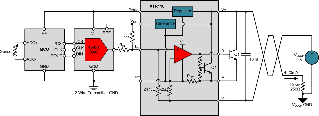
Figure 1: 2-wire sensor transmitter with MCU+ADC and DAC

Figure 2: 2-wire sensor transmitter with MCU+ADC and PWM DAC
As I explained in my previous posts, the MCU and DAC must be fully powered between the VREG and IRET pins of the XTR116, and the IRET pin must not be connected to the VLOOP GND or to any other external voltage potentials. Also, the circuitry powered from the loop must consume less than 3.8mA so that the XTR116 can properly output the 4mA zero-scale level.
While the system designs shown in Figures 1 and 2 are common, you will occasionally have to design a system using an MCU powered from a voltage source referenced to another external potential, possibly VLOOP GND, to control the output of a 2-wire transmitter. Figure 3 shows an example of this type of system.

Figure 3: Issues with controlling a 2-wire transmitter with an externally powered MCU
In this type of system, the sensor and MCU can’t be directly connected to the DAC or PWM filter circuitry. If the sensor and MCU are directly connected, the 2-wire transmitter GND pin (IRET) will be pulled down to VLOOP GND, or another voltage potential, preventing the transmitter from functioning properly. Even if the GND pins aren’t connected, trying to connect the externally powered MCU output signals to the transmitter will cause issues because the sensor GND currents will try to find a return path through the 2-wire transmitter.
Therefore, as shown in Figure 4, you must use a digital isolator between the sensor and MCU circuitry and the 2-wire transmitter circuitry. Integrated isolation solutions such as the ISO7310 can accomplish the digital isolation. However, be sure that the digital isolator doesn’t consume more than the allowed current budget for the 2-wire transmitter.
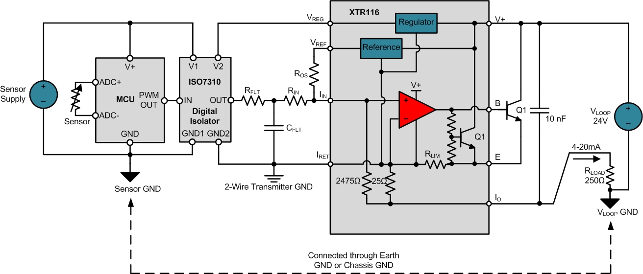
Figure 4: Isolating an externally powered MCU from the 2-wire transmitter with the ISO7310 digital isolator
In summary, if you’re trying to control the output of a 2-wire transmitter from an externally powered control source, be sure to include a digital isolator between the controller and the 2-wire transmitter circuitry to prevent the grounding issues I described in detail in Part 2 of this series.
In Part 5 of this series, I’ll discuss the design of 2-wire sensor transmitters that require the sensor circuitry to be powered from, but also be completely isolated from, the rest of the 2-wire transmitter. These systems are commonly called “input isolated” or “sensor isolated” 2-wire transmitters.
Related TI Designs reference designs for 2-wire transmitters:
http://www.ti.com/tool/TIPD126
http://www.ti.com/tool/TIPD158
Related 3-wire blog posts from my colleague Kevin Duke:
- See an overview of analog outputs and architectures.
- Read about the evolution of 3-wire analog outputs.
Find commonly used analog design formulas in a new pocket reference put together by Art Kay and Tim Green.

