This thread has been locked.

If you have a related question, please click the "Ask a related question" button in the top right corner. The newly created question will be automatically linked to this question.

LMP7718: Stability analysis of TIA with DC servo

Part Number: LMP7718
Other Parts Discussed in Thread: OPA320, LMP7717

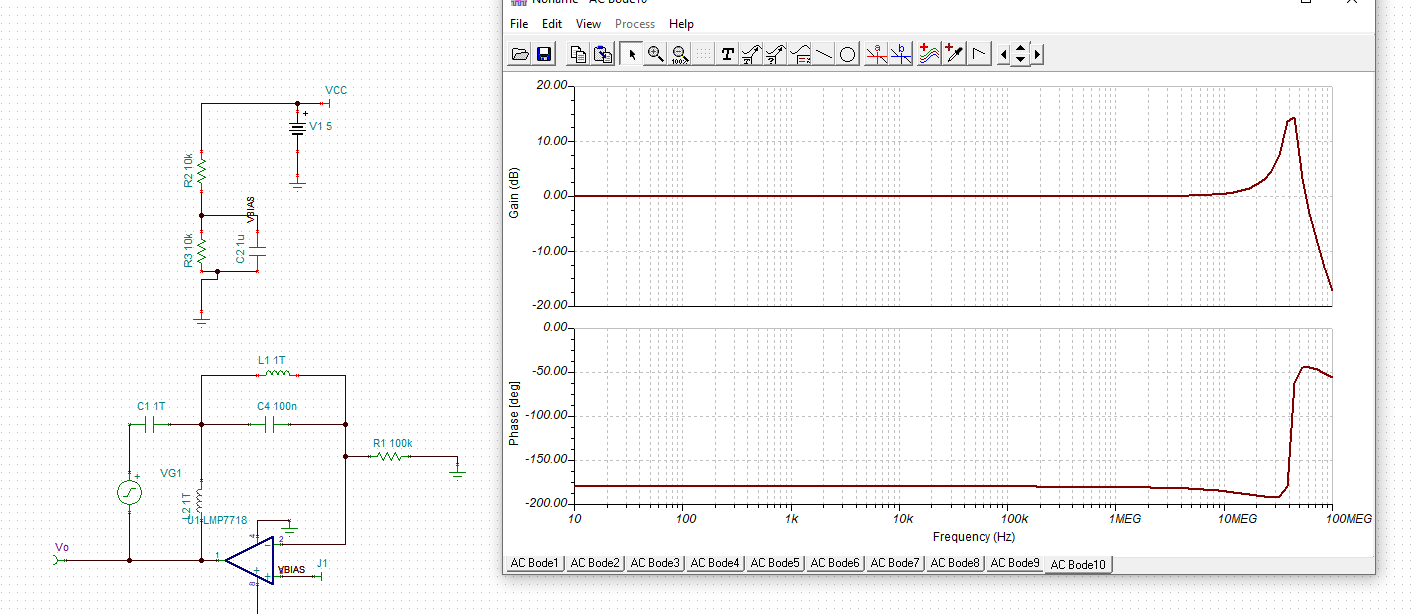
I need something close to a 1 Mhz TIA for interfacing to a photodiode.  It has to work indoors and outdoors, so I'm looking at DC coupled, but including an additional op amp that will keep the TIA biased regardless of DC (or low frequency) noise:

(The 1T inductor and capacitor are just there to break the loop for AC analysis).

The design will need 24 of these (pair of light curtains), so op amp cost is important.   Using an uncompensated op amp like a LMP7718 seems more cost effective than using the OPA320.   But, I suspect that I need additional stability compensation.

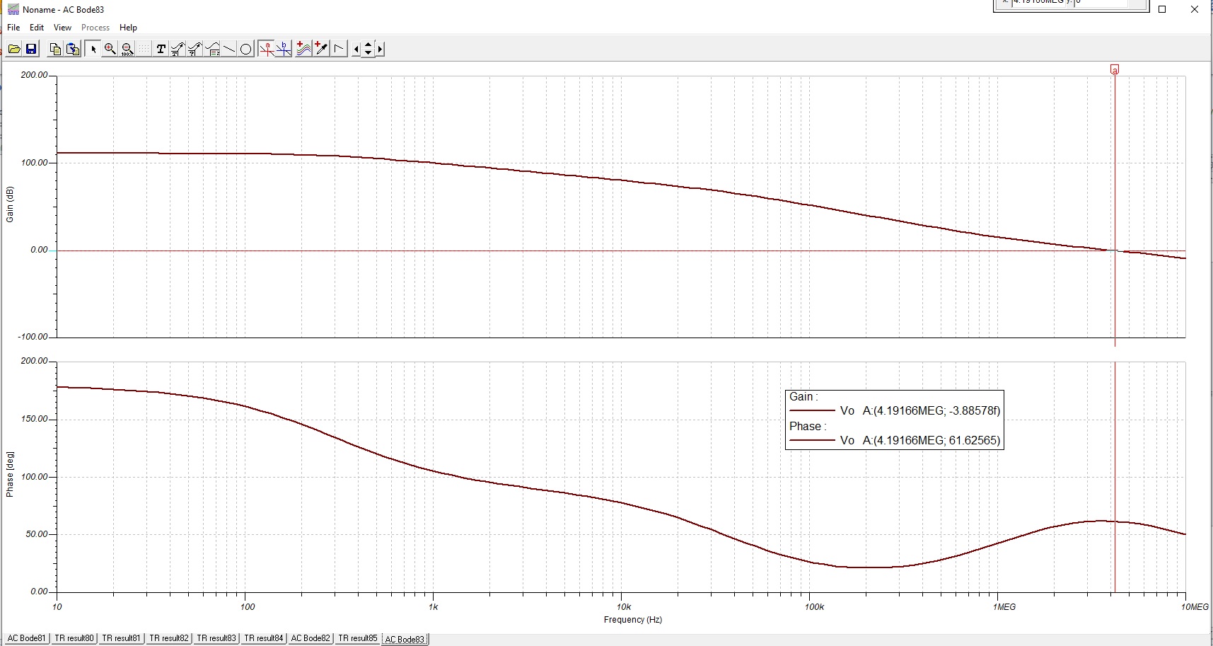
When I do the open loop plots, I get this:

It's been a long time since I did this type of a thing for a living, so please forgive me if I'm asking a stupid question.  

Literally, the phase margin is 61 degrees--at least the phase of open loop gain when the gain is zero.  But, notice the phase got much closer to zero (41 degrees) when the gain was still quite high.  Don't I have to worry about that?

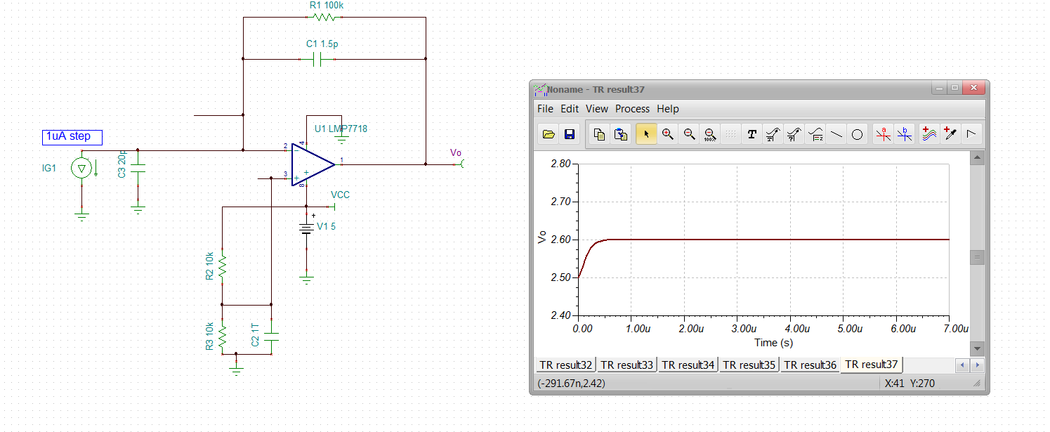
I did a step response and saw a very large amount of peaking.  Several times bigger than the settled output change.

Am I correct in thinking I've got a stability problem? Changing the feedback cap doesn't seem to affect the phase margin where the gain is still very positive, nor the frequency at which that occurs.  Changing the cap in the DC feedback amp doesn't change things much either.

This is an uncompensated op amp, but I saw very similar results with the OPA320.  Everything made sense if I used AC coupled instead of DC coupled with the DC servo.  But, when I add the extra op amp generated feedback, I'm getting lost.

Any help would be appreciated!

  • When I copied the schematic, I left out the emitter resistor for T1.  But, still the same issue remains.  Phase gets closer to zero at lower frequencies than what it is when the gain goes to zero.

    Seems the definition of "phase margin" should consider the lowest phase shift (from 0 degrees) while the gain is more than one?  Not just the margin when gain is 1.

    If I'm right, hints on compensation technique is needed.

  • I found this post about compensating the LMP7718:

    https://e2e.ti.com/support/amplifiers/f/14/t/810936?tisearch=e2e-sitesearch&keymatch=OPA277

    With Cs of 20p, Rf 100k, I get .56pf for Cf.   But very similar results.  Phase nears 0 degrees way before the unity gain crossover.

    What am I missing?

  • I simplified the circuit to first focus on why I get the non-monotonic phase versus frequency characteristic.  Turns out, I get that without the DC servo loop even with the OPA320.

    In fact, the article shows this

    Is the phase margin really 68.59, or is it in fact, closer to 30 degrees (where the phase gets closest to zero.

    Does checking the phase at 0 gain really only work if the phase plot is monotonic?  If not, can this be explained?  If you must consider the closes phase to zero when gain is greater than zero, does the  1 Mhz IR prea (TI reference design) have a stability issue?

    Thanks!

  • Forgot to include the URL for the TI reference design (where the Bode plot came from):

    http://www.ti.com/lit/ug/tidu535/tidu535.pdf

  • Hey Dave, actually, that loop gain phase dip to -180deg midband is pretty normal for transimpedance - no problem with that, what happens around LG=0dB is setting the closed loop response. At midband, that LG magnitude is still quite high, so the LG/(LG+1) is still close to 1. That shows up as figure 11 in this recent article, this one also gives you a simple transimpedance compensation flow. 

    1768.Applying High Speed DeCompensated VFAs July1_2019.pdf

    can you attach your TINA file with servo

  • Thanks for the reply, Michael!

    The Tina  file is attached.  (but, I'm not sure if the file is compatible with the way I did it using the paper clip icon)

    1 Mhz IR Preamp with DC Servo AC analysis 7718.TSC

    I can't  spend more time today today, but tomorrow I'll look at the article you referenced.

    Ideally, I'd have a narrow band filter around something like 1 Mhz.  Maybe I don't need the low pass above 1 Mhz--probably not much IR up  there. 

    I don't want to add another op amp for filtering--I need 24 instances of the circuit.  There will be another pnp transistor and RC at the output of the preamp for 1 Mhz envelope detection.

    But, I'm considering making the DC servo amp circuit a 2nd order low pass.  That way I could keep the low frequency gain of the closed loop response as low as possible for as high a frequency as possible.  (but still getting the required gain at 1 Mhz).

    Do you think an extra pole in the feedback loop would make compensation impractical?

    Is there another way to do it without adding another op amp? 

    I'm just trying to detect presence/absence of 1 Mhz signal.   What were  using now (Vishay TSSOP6038, but down at 38K hz) requires 10 cycles for reliable detection.  That's higher Q than I can probably afford to implement, but trying to find any "low hanging fruit".

    Thanks!

    Dave Thomas

  • Wow, took a "sneak peek" at the article.  Seems it covers TIA with filter application.  Wonderful!

    I'm looking forward to diving into it.

    Thanks again!

  • You bet Dan, there are few more global things in that article covering decomp VFA's beyond transimpedance, but for a pure transimpedance discussion - this presentation covers a lot of what you might need simplified down to  a simple design flow (not servo loop though - make sure you include that transistor capacitance in your compensation for the Zt stage). The servo loop idea is a good idea to AC couple blocking out background light, but that transistor C needs to be low if possible. 

    8547.Transimpedance design flow using high speed op amps.pptx

  • Also Dan, you probably should use a unity gain stable op amp for your servo amps. 

  • Running just your Zt stage looks fine, is 1MHz enough for you - if too much,you have room to increase the gain. 

  • Thanks, Michael.

    I have several questions.  Let's start with:

    Running just your Zt stage looks fine

    Did you look at the step response?  

    There's a lot of overshoot in the response!

    Here's the .tsc I used:

    1 Mhz IR Preamp step.TSC

    I'm still not clear why a phase shift approaching zero when there is still a lot of open loop gain isn't a concern.  If the phase shift got all the way to zero with the loop gain greater than one, wouldn't the circuit oscillate?  If you agree on that, isn't how close it comes to zero an indication of stability, especially if that's a high loop gain?

    At least one "legacy" article mentioned that phase margin was the phase when the loop gain crossed one, but only becaus most phase versus frequency characteristics were monotonic. (TIA is an exception)  The article didn't explicitly say the phase margin was actually the smallest phase wherever the gain was greater than one, but I was thinking that was the point.

    -----------------------------------------------------------

    Yes, I see the same phase curve in the article you referenced and in the TI reference design.  But, did you check the step response?  Maybe I have a mistake in my simulation, but if not, doesn't that look like insufficient phase margin?

    ---------------------

    I went through the articles you referenced. Very straight forward and helpful.  Thank you! 

    But, what changes if I don't care about a flat response curve?  In fact, the steeper the low frequency roll off, the better for my application.  I just one to detect the presence of a 1 Mhz signal.

    ----------------------------------------

    Which capacitance in the npn transistor (in the DC servo loop) should I minimize?  Cbe?  Can you elaborate on why?  

    I was actually thinking about where I could add a pole in the DC servo loop to get second order roll off in response in the feedback (so the gain increases at 40 db instead of 20 db per decade).   One way would be to add a cap in parallel with resistor on the emitter of that npn. 

    Will something like that be very difficult (or maybe impossible) to compensate?

    Alternately, I was thinking about keeping the DC servo loop to keep the photodiode optimally DC biased AND adding an AC coupling cap to provide the desired high pass characteristic at frequencies below 100 Khz.  Then a 2nd order passive filter on the output of the preamp.

    Remember, I'm trying to get a narrow band filter around 1 Mhz, not a flat band response up to 1 Mhz.

    -------------------------------------------------------

    I understand that using a unity gain amplifier for the DC servo would be simpler.  But, that would rule out  using dual op amps.  That's a big cost and pcb layout hit.  If I have to add another amplification stage to post filter the pre-amp output, the incremental cost to use a unity gain amp wouldn't be so bad.  But, I want to first see what I can do to get the desired frequency response without adding another amplificaiton stage.

    Thanks again!

    Dave Thomas

  • Too many questions for me to handle, but a couple of things, 

    1. Your sim was using a voltage step on the V+ input, yes that will show an AC coupled peak then decay due to the inverting source capacitance, if you go to a current source only on the Zt input side, looks great - 

    2. Well I think you said you had a lot of channels to build - make all the Zt stage dual OPA7718 and all the servo channels dual or quad unity gain low cost CMOS op amps. - don't need much GBP there, while the Zt does. 

  • Sorry about too many questions.  

    I did the voltage step on the + input since a current step into the cap doesn't create a unit voltage step, but rather a voltage ramp (due to the integration of the cap).  

    I've seen the positive input used for the step in op amp circuits where the zero impedance of  voltage step on the actual circuit input would affect the circuit operation.  So, I figured that was the right way to do it (versus a current step into a capacitor). No?  Is using a current step the accepted practice for simulating TIA step response?

    Sorry for staying with this, but think I really need to understand why phase is only important at the open loop unity gain point before I can do anything beside choosing different component values for a specific topology.  

    -------------------------------

    Yes, I need 24 instances of photo detectors, but they are physically distant (3") from each other.  So, it's not practical to share op amp packages between two sensors.   Running small signal nets back and forth that 3" is not good from a noise susceptibility stand point.  Also the pcb width dimension is constraining.  The extra space to route the wires around the processor and supporting circuitry between each pair of sensors would result in a wider pcb.

    If I really have to have unity gain for the DC servo amp, I'd go with single circuit op amps.

    ----------------

  • On the question about what stability margin when the phase approaches zero more closely at high open loop gain than at the unity gain cross-over:

    https://electronics.stackexchange.com/questions/139846/stability-and-loop-gain-of-negative-feedback-systems

    I see both answers, you DO have to worry about 180 degrees of phase shift before the unity gain crossover and that you do NOT have to worry about it.  

    So, I guess it depends on who you listen to?

    Anyway, that's why I wanted to try the step response as a sanity check.  But, what's the right way to apply a unit step in simulation?  Do different methods give drastically different results.

  • Just to bring out the two different answers:

    The concept of checking the phase angle at unity gain only applies to simple systems in which the phase-vs-frequency plot is monotonic, where the assumption is that the phase angle is only increasing with frequency, and that as long as the phase margin is sufficient at unity gain, then it can only be better at lower frequencies... Any system that has greater than unity gain and a total of 360° of phase shift (including systems with inverting amplifiers and 180° phase shift) at some frequency will oscillate.


    The other side of the argument:

    Here is an explanation why the closed loop (your example) will be stable: If a closed-loop system is unstable, this point of instability also must be "stable". That means - either we will have "stable" and continuous oscillations or the output is latched at one of the supply voltage rails. In both cases, this point of instability is fixed.

    Now - what happens at the point A in your example? Here we have a rising phase which is identical to a NEGATIVE group delay at this point (group delay is defined as the negative phase slope). This is an indication for the unability of the closed-loop system to let the amplitudes rise (oscillations or latching at the supply rail). Rather, the system returns to a stable operating point.


    This seems like an important point.  When I synthesis a compensation network, need I only worry about phase at the unity gain cross-over frequency, or is it really the worst case "phase margin" over the entire frequency range where the gain is greater than 1.

    .

  • Bringing it back to an actual example, to illustrate it' not "just a hypothetical question":

    With the DC servo loop including, using the uncompensated 7718 for both the DC servo amp and the TIA preamp, and just a 2N222 npn transistor (not particularly low capacitance), I see the open loop frequency response below.

    Using the phase at unity gain crossover, phase margin is greater than 60 degrees.  But, the phase gets down to only 21 degrees when the gain is 45 db.

    The step response when using a current step into the cap is well damped.  But, a unit step at the + input of the TIA amp produces an overshoot many times greater than the settled output value.

    Does this design look good, or do I need more stability analysis?  

  • I think this is now a dead thread and Michael provided some good reference info.  So, I'll check the "this resolved my issue" box--probably Michael gets credit for that.

    But:

    1) I still worry about phase approaching zero when gain is very high

    2)  Don't know why Michael said I should use a unity gain compensated amp in the DC servo loop (the open loop phase/frequency response looks as good as standalone TIA when the non-compensated 7718 is used

    3)  Don't know what npn  (in the DC servo loop) capacitance Michael said it was important to minimize, nor why.

    4)  Don't know if it's foolish to try to get 40 db (or higher) low frequency roll-off by adding low pass filter in the DC filter loop. 

  • 1) I think in some power systems you can get into trouble with midband phase shift more than 180deg. But this transimpedance design has always worked fine with that midband dip - I did answer, LG/(LG+1) is one way to think about instability - if LG is -180deg at LG=0dB (1) the then denominator blows up - if,however, LG is large with a negative real part (close to -180deg) it is still well behaved as a LG/(LG+1) term. 

    2)You should try just the integrated stage by itself in a LG sim, is should oscillate being decomp with straight C feedback

    3)NPN Ccb capacitance will add (I think) to the diode C - look at the 2SD2226K

    4) You could also add a high pass pole after the transimpedance as a C R stage. 

  • Thanks for again helping out, Michael.  As I mentioned, it's been a long, long time since I've done amplifier design and stability analysis.

    1)  I understand your argument about LG/(LG + 1).  But in my head, I"m thinking that if a signal is feedback, in phase with the output and amplified, an oscillation will occur.  Maybe the IR pre-amp circuits work ok, but really need (and have) less stability margin than required for the applications.

    I was thinking about adding RC networks to get a narrow band frequency response--being constrained only by the phase margin at the open loop unity gain crossing is much less restrictive than looking at the minimum phase over the entire frequency range when gain is greater than one.  But, I think it's time to move on and shape the frequency response at the preamp output (as you suggested in 4).

    2)  I did as you suggested, and I do see negative phase margin at the 0 db crossover:

    I guess I'll have to use an LMP7717 (single device) and a unity gain compensated op amp ( like you suggested ) in SOT23-5 packages.  Do you have a low cost recommendation? 

    Sorry about yet another question.. why do I not see an issue in the open loop simulation that includes both the integrator AND the TIA feedback loops? 

    3)  I guess I'll start by adding a Ccb cap to and determine the circuit sensitivity to it.  The base has resistors to ground, so I wouldn't think it would add directly to the total Cs.  Thanks for the alternate part to try.  I'll also see if I see a difference in overall frequency response/phase margin with it versus 2N2222.

    4)  Yes, I was already doing that.  Just trying to get as much low frequency roll off as possible in the pre amp stage, if that could be done easily. But, it seems it gets me "off the beaten path" too much.  Besides, I really don't know how much roll-off I really need.  I was just trying to get as much as the IR remote control chips have without having to add an active filter.  

    Thanks again for your support!

    Dave Thomas

  • before I move on to finishing this slew rate article, here is that Rohm transistor model - they seem to do a pretty good job, TINA file below, 

    2SD2226K NPN.TSC

  • Thanks Michael!

    I don't see any difference in either the closed loop or open loop AC response using the 2SD2226K versus the 2N2222.

    Dave