This thread has been locked.
If you have a related question, please click the "Ask a related question" button in the top right corner. The newly created question will be automatically linked to this question.
Hi Team,
Please
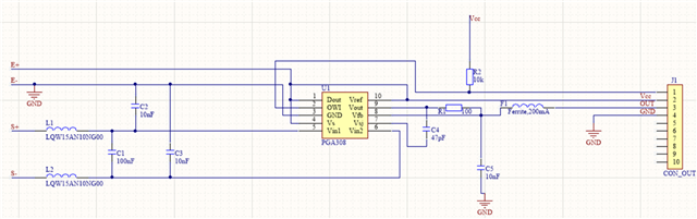
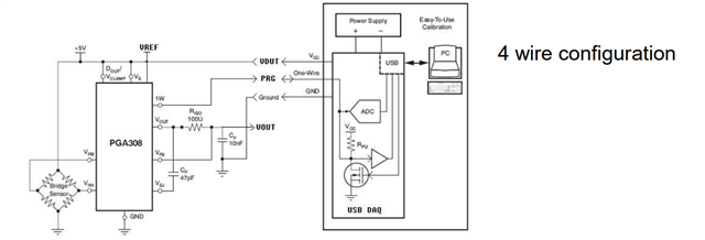
My custom circuit with PGA308 is shown below.R2 is removed for real circuit.
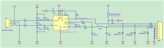
And we try to calibrate this external sensors follow the connection below:
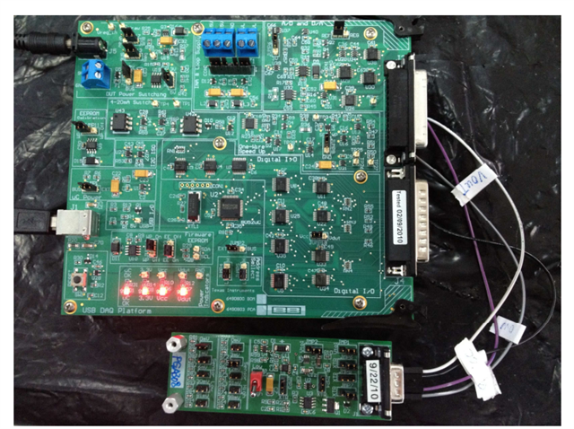
For the calibration steps as below, I follow the PGA308 EVM board steps, but I don't have the calibration procedures for external sensor board.
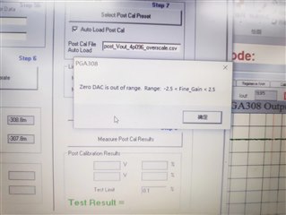
Issue:
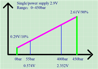
The connection seems work and power supply is good. However, when we change the bridge sensor output there seems no change in the block diagram and the Vin reading is incorrect.
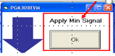
From my understanding, I should change the step 2 from "Use DAC Signal " to "Apply signal externally". But do you have a special configuration guide for other mandatory stetting I should take care. I really need this kind of suggestion. Thanks a lot.
Best Regards,
Tess Chen
Hello Tess,
It appears that you have connected a multi-cal-test PCA card directly to the USB-DAQ platform. The multi-cal-test PCA card is designed to be used with the larger multi-cal system and is not directly connected to the USB-DAQ. Can you show the connections and test configuration that you are using with your custom board?
Do you have the PGA308EVM as pictured below? Were you able to perform a successful calibration using the PGA308EVM Software and the onboard signal emulator?
The PGA308EVM allows an external sensor to be connected using terminals T3 and T5, and configured as the input source using JMP17 and JMP18.
Follow these steps to ensure the input from the external sensor is as expected and within the common-mode input range of the device. Connect your external sensor to the PGA308EVM as described above, and use a precision multi-meter to verify the input common-mode voltage of Vin1 with respect to GND and the input common-mode voltage of Vin2 with respect to ground. Then verify the differential voltage across Vin1 and Vin2 under no-load and full-load sensor conditions. When loading the sensor, make sure the load is stable and give the sensor adequate time to settle before taking the measurement.
If these voltage measurements are as expected and within the common-mode input range of the device, the next step is to calibrate using the external sensor, the PGA308EVM and the PGA308EVM software. You will need to change step 2 to "apply signal externally" when using an external sensor. In the block diagram tab, you should be able to see the Vin reading change when loading/unloading the sensor.
Following the steps above will validate that the sensor signal range and the software set-up are correct and the next step is to attempt calibration using your custom board.
I have some additional comments and questions about your custom board.
1.) What is the E+ voltage on your custom board schematic?
2.) I do not see any bypass capacitors on your schematic. Keep in mind that local 100nF bypass capacitors are recommended at the Vref and Vs pins (see section 3.10 of PGA308 datasheet).
Hi Zach,
Thanks for your prompt reply.
1. To clarify the connection: I don't have a PGA308EVM in hand and just have the USB DAQ board. I self made a PGA308 Test Board follow the schematic below.
Bridge sensor---> PGA308 Test Board--->USB DAQ--->PC EVM GUI
I understand your comments that PGA308EVM can support external sensors. But I am wondering whether my connection could also use the EVM GUI to do Calibration and OTP?
2. If the answer above is yes, what's the necessary change in the GUI that I should change.
3. When we just have the Bridge sensor---> PGA308 Test Board (powered from a source generator) these two part to test the power on sequence, we find the output or Vin1 and Vin2 is correct provided. But there is no output for Vout of PGA308.
Does there a default OTP configuration from the factory before we do manually OTP writing to make the chip working? I assume that the wrong Vout is due to we don't successfully finish the calibration and right OTP setting?
We are really struggling for the configuration and looking forward to your reply. Thanks a lot.
Best Regards,
Tess
Tess,
Yes, you can use the PGA308EVM software to calibrate your PGA308 Test board.
You do not need to change the values in the block diagram tab as these will be automatically updated when you set the Cal Preset in step 4 of the calibration tab. You will need to set Vref to the correct value and I recommend selecting the "Clamp" setting as well.
After you update these settings and click "Ok" you will be prompted to save the settings in a .csv file.
In step 2 you will need to select "Apply Signal Externally" for your external sensor.
Note that pins ads2 vin+ and ads2 vin- on the USB_DAQ are typically connected to the inputs of the PGA308 to measure the differential input signal. You do not have this connection on your board, which is why the Vin reading on the block diagram page does not change in response to your input signal. You may complete calibration without this connection, as the calibration procedure only requires the output of the PGA308 to be connected to ads1 vin+ which you have connected correctly. For this reason you may select "Use USB DAQ A/D" as your measurement tool in step 3.
Yes, you will need to complete the calibration procedure and write the values to OTP to get a valid output signal.
Hi Zach,
Thanks for the guidance. We still meet one issue for the calibration steps:
Schematic:
Target calibration curve:
Connection to USB board just follow the 4 wire connections as above.
For calibration configuration:
Issue: when we go to step 6 calibrate, "apply min signal" pop up, PGA308 sensor input is 0. When click OK, the PGA308 output immediately change to 2.498V reading by DMM. It is abnormal because the input is zero now. Then the "apply max signal" pop up, adding any pressure to the input will cause the "Zero DAC is out of range" alert shown below.
Could you please help check the configuration?
Does step 1 need to change any value? Step 5 is needed ? or any other suggestion is welcomed. Thanks a lot for your help.
Best Regards,
Tess Chen
Tess,
I am having trouble reading the screenshots in your most recent comment as they are very low resolution so I will do my best to address this issue.
It appears that in the cal preset (step 4) you have set the supply (Vs) and reference (Vref) to 2.9V? Based on the schematic from a previous comment I believe that your power supply and reference voltages are 5V, is this correct? If so you will need to set Vs and Vref to 5V in step 4.
What is your sensor excitation?
Can you confirm when the sensor is at zero scale, the target PGA308 output voltage is 0.29V?
Can you confirm when the sensor is at full scale, the target PGA308 output voltage is 2.61V?
Set the Vs and Vref to the correct value as described above and if you still have trouble please resend the schematic image in a higher resolution and also send the cal preset .csv file.
Regards,
Zach
Hi Zach,
As this post contain two much info, I will contact you through e-mail. Thanks.
Tess
Tess,
I understand, I will go ahead and close this thread and we will continue addressing this over email.
Thanks,
Zach