This thread has been locked.

If you have a related question, please click the "Ask a related question" button in the top right corner. The newly created question will be automatically linked to this question.

LM124A: What does LM124 A, J, P, B, ... mean?

Part Number: LM124A
Other Parts Discussed in Thread: LM2902, LM124, , LM148

1.  What do the "A, J, P, B, ..." Options mean in the part number?  We used part number LM124AJ 14-pin CDIP in an amplifier design that we made back in 2000.  Some customers need more of the amplifiers and we need to know if the part is still available and what the lead time is.?

2.  Also, in the old National Semiconductor datasheet, it specifies that the part can operate with differential power supply up to +/-32V (I think).  I would like to know if the new parts still operate with differential source power and if so, what is the max source voltages?

3.  If the LM124AJ in 14p CDIP is not available, what fully compatible drop-in replacements do you offer?  Can I run an LM2902 the same way with +/-15vdc

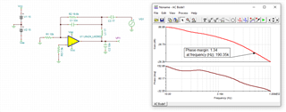
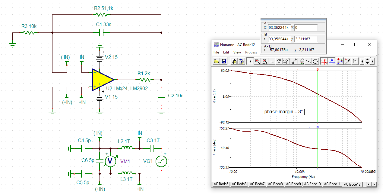
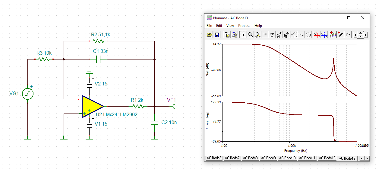
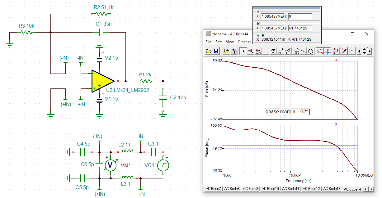
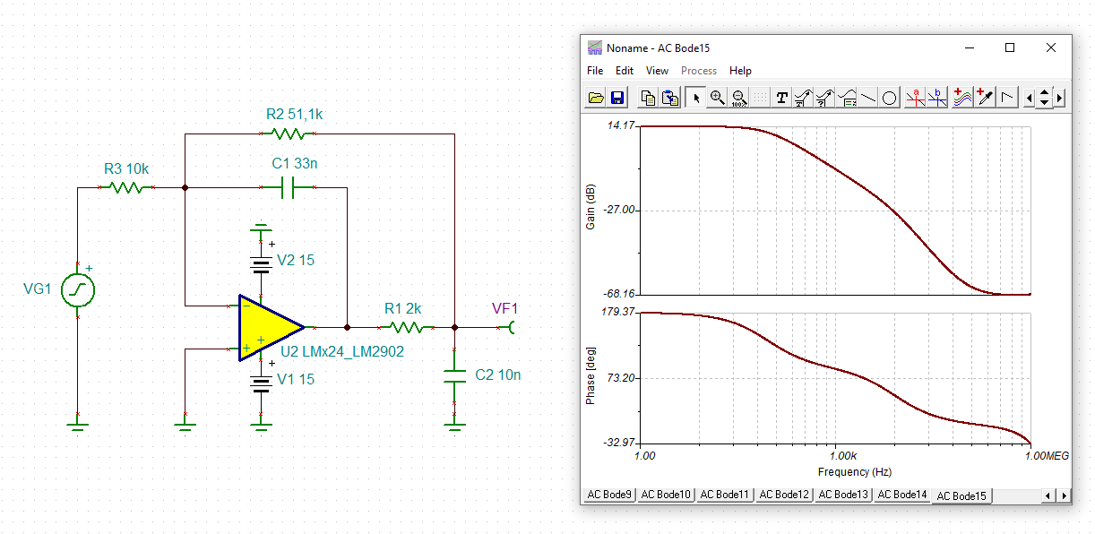
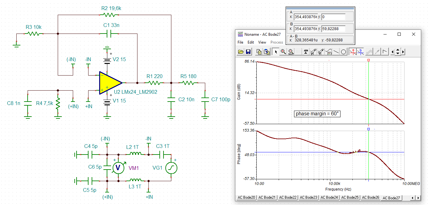
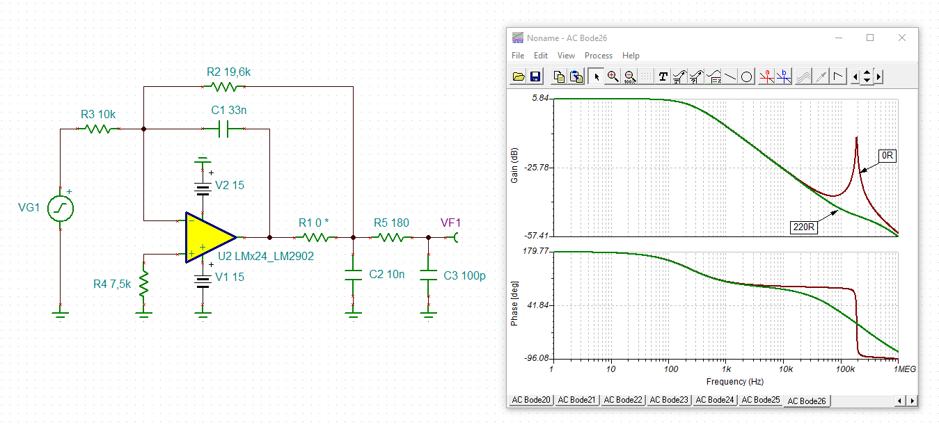
4.  Finally, I have a amplifier board that has three of these units on it and we are experiencing a lot of what looks like noise.  I cannot tell if it is EMI, noise, or reflections but we do know it is coming from the amplifier board.  Can you tell me if there is anything that be missing that could cause unusually large noise or reflections?

thanks,

Vincent

  • Hey Vincent,

    1. The A suffix typically denotes an A revision of the part, usually for smaller offset voltage, this seems to be the case for LM124/LM124A.
      The J suffix is a package suffix, which designates CDIP package.

    2. The max supply voltage is +/-16V or 32V. They operate with single supply or dual supply. 

    3. Here is a filter of our military CDIP devices sorted by highest to lowest inventory, we have LM148 and several others. If you could provide a schematic or some necessary specifications we can verify if it will work as a drop-in replacement. LM2902 has a max supply voltage of 26V, so I would not use it at +/-15V

      https://www.ti.com/amplifier-circuit/op-amps/general-purpose/products.html?login-check=true#p2954=CDIP&p1498=Military&sort=p3318;desc
       
    4. Are there any scope shots you can provide of the apparent noise or a schematic?

      Depending on where the noise is relative to your signal of interest you could be missing input/output filters or if the circuit is unstable it could be oscillating and presenting as noise. Without a schematic or some scope shots, it makes it hard to point to a root cause.

    Best,
    Jerry

  • IH3136-sh6_AMP.pdf

    This is great info, thanks.

    Here is a schematic copy of my amp circuit and/or the scope shot?

    If you cannot see it them call me or email me..

    Thanks,

    Vincnet

  • Hey Vincent,

    I see some unusually large capacitances being directly driven. C15, C16, C14, C13. Earlier in the signal chain you have these 10nF caps being isolated by an isolation resistor.

    You can validate this in a quick TINA sim to see if you have sufficient phase margin. It looks like you have about 1 degree of phase margin.

    I've attached my TINA sim below.

    LM124_LM.TSC

    Adding an isolation resistor as small as 100 ohms gives you 53 degrees of phase margin, which is much more stable.

    Best,
    Jerry

  • Hi Vincent,

    I fully agree with Jerry, your circuit is instable. This can not only be seen from the eroded phase margin in the phase stability analysis but also from the frequency response showing a sharp resonance peak:

    vincent_lm124.TSC

    vincent_lm124_1.TSC

    A way better aproach, provided you want to keep the 10nF cap at the output, would be to connect the 33nF in a way to be able to provide a phase lead in the feedback loop of OPAmp as done in the well known "dual feedback technique":

    The second LM124 amplifier in your schematic I will discuss later.

    Kai

  • Hi Vincent again,

    the second amplifier is also instable and shows the same symptoms. Adding an isolation resistor, as already suggested by Jerry, can dramatically improve the stability:

    As you can see I would recommend an isolation resistor of 220R and a 1nF cap in parallel to the 7k5 resistor. This gives a phase margin of 60°, which should always be the aim of a design, to accomplish a phase margin of more than 60°.

    Kai

  • what if I just remove both of the feedback caps in both phases of the amp circuit.  I really just need a current to voltage stage then an amplification stage to take +\-50uA and produce +/-5 Vdc.  Thanks

  • Where are you suggesting I add the isolation resistor? 

    Also, we have a legacy version of this circuit that seems to be stable.  I thought I copied the ckt except for the gains changed and offsets removed.   I see where the first stage double feedback circuit is configured incorrectely.  Can I just remove the feedback caps?

    See attached.  below...

  • Hey Vincent,

    Feedback caps generally help your stability. Higher gains are also more stable. The main issue is the load capacitance introducing too much phase lag causing instability, which can be compensated through a simple isolation resistor or an isolation resistor with dual feedback like Kai mentioned

    The isolation resistors are placed between the output of the op amp and the load capacitance.

    Best,
    Jerry

  • are you suggesting I add a 100 ohm resistor at the output of the second stage like the 2K at the first stage?

    i am really trying to fix this without any new spins of the board - just component replacements.  (If possible)

    Thanks,

  • thank you very much for your help

  • when I try to simulate a bode plot of these circuits using a spice simulator called Multisim (from NI), I don't see the spike that you mentioned.

    What frequency is this at?

  • Hi Vincent,

    you can read the resonance frequency from my simulation picture. It's 200kHz.

    Are you using the latest Spice model? The one I use is from 2018. I know that there are lots of older Spice models arround which are very rudimentary.

    As a quick fix of my first simulation, short the 2k resistor, remove the 10nF cap at the output and decrease C1 to 33pF. If you want to add a capacitive load to the circuit, then insert a 100R isolation resistor (R1) as shown below:

    The mistake here is not only the too big capacitive load at the output, but also the too big phase lead capacitance C1. Only a small phase lead capacitance will do the trick here.

    Please specify which circuit exactly we shall cure for you.

    Kai