This thread has been locked.

If you have a related question, please click the "Ask a related question" button in the top right corner. The newly created question will be automatically linked to this question.

OPA657: Output noise of OPA657

Part Number: OPA657

Hi,

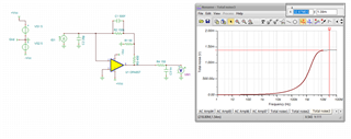
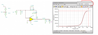
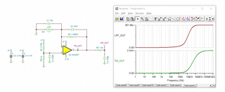
I'm testing the output noise of following circuit using OPA657 as TIA to amplify a PD. The output noise of LPF_OUT could reach 20mVp-p, which is much larger than the simulation result (0.85mV*6.6 ≈ 5.6mVp-p).

I also did calculations but the result was smaller than the simulation one so I don't paste it here.

What I have confirmed : 

  • The noise stay the same without the DC bias voltage (not shown in the simulaiton scheme), so it should not caused by the ripple/noise from DC-Bias driving voltage for the PD.
  • The noise stay the same without the PD, so the noise is not cuased by the dark/short noise of the PD. 
  • The ripple of the positive/negtive voltage is less than 3mVp-p. 
  • The temperature coefficient of gain resistor is no more than 15ppm/C.

Before I move to next test I'd like to get some hints if anyone can help, thanks!

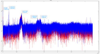
Updates: Improved test setup. With PD working under DC-Bias in dark environemnt. Current background noise is around 12mVp-p. And it seems major part of the noise is from the Rf - little strange compared with calculation/simulation, the feedback resistor shall not contribute so much as a 10ppm/C type is used.

  • Hello Follin,

    I have been busy with lab work today, but I will take a look at your post this week.

    I will let you know if I have any follow-up questions.

    Best,

    Alec

  • Hi Alec, great, looking forward to your reply:)

  • Hello Follin,

    Quick update: my coworker Sima & I are looking into your question this week, we will strive to provide an update by the end of the week.  I appreciate your patience on the matter.

    Best,

    Alec

  • I think we were talking about this one for BW, I still had the Tee network one open and ran it for output noise rescaling for lower R in the Ouput RC but the same pole location, 

    And then modifying this back to yours, 

    So this matches what you showed above, so to compare to measurements, more detail on how you are doing that is needed. What is the baseline noise for your probe without probing the DUT. 

  • Target of back ground noise is 3~5mVp-p. But T network is pretty good with respect to BW, I'm preparing a T network version for test to see which is better for SNR. But before that I just want to optimize this version as possbile.

    BTW: I've confirmed major part of the noise should be caused by the Rf - even I used a 10ppm/K resistor. So I guess the current noise from OpAmp is noI so small as I expect.

    Thanks!

  • Hi Follin,

    for lowest noise it's important to use state-of-the-art resistors in your circuit. Never use thick film resistors but only highest quality thin film resistors:

    https://quantasylum.com/blogs/news/a-cmos-pre-amp

    Especially the high ohmic feedback resistor is critical. Sometimes it can help to replace the single feedback resistor by a series circuit of smaller resistances, because smaller resistances can show considerably lower noise. This has to do with the fact that high ohmic resistors see a different manufacturing process. Also, different materials are used for high ohmic resistors which generate a higher noise.

    A series circuit can also help to minimize the unwanted parasitic parallel capacitance of feedback resistor, because the total capacitance decreases when caps are put in series.

    As the link shows, the bigger the resistor package the lower the noise. So, avoid using 0402 resistors but choose an as big as possible package. Of course, the HF performance must not suffer and the OPA657 must still run stably.

    There's another fact: Keep in mind that above the corner frequency of 1 / (2 x pi x 1.5MOhm x 100fF) = 1.1MHz only the 15pF and the 100fF capacitances determine the noise gain, resulting in a noise gain of 150V/V. All the OPA657's noise is amplified by a factor of 150V/V above this frequency!

    Kai

  • Hello Follin,

    Kai is absolutely right: informed component selection is critical for successful layout; there are often cases where the resistor (usually Rf) noise (see Nyquist Thermal Noise equation/paper) dominates compared to the voltage and/or current noise of the op-amp.  Especially at higher temperatures!

    If you need additional resources outside of what has been discussed in the thread, I can look to see what we have on the subject.

    Best,

    Alec

  • Hi  Kai,

    Currently I'm using RG2012P-155-B-T5 0805 thin film resitor. The series resitors open my mind but I need more space on the PCB :( .

    I've tested more, all of them are thin-film and 0805

    Rf = 1.5M(25ppm/K) 10.6mVp-p

    Rf =  1.0M (10ppm/K) 8.19mVp-p

    Rf =  0.1M (10ppm/K) 2.89mVp-p

    I tested the noise after filter and get the fft spectrum, the noise peak is at 50Hz, 22kHz, 68kHz, 126~136kHz, noise after 1.1MHz should be filtered pretty well :

    Trying to find the route of 50Hz and source of 22kHz,68kHz,126~136kHz noise (seems to be harmonic of 22kHz)

    Thanks for your reply and reminding. 

  • Hi Follin,

    50Hz is mains hum and 22kHz plus harmonincs can come from a modern LED lamp or any display of your measuring equipment.

    I hope you your circuit is properly shielded by the help of a Faraday cage? Connect the Faraday cage to signal ground.

    Kai

  • Currently I'm using RG2012P-155-B-T5 0805 thin film resitor.

    Yes, this Susumu resistor should be well suited.

    Kai

  • Yes I have designed metal shilded parts but haven't assembled it on the PCBA. Will test it soon.

  • Hi Kai,

    I used the metal shielding part to cover both top and bottom side of the PCB. There's no obvious changes. But when I touched the metal part, the noise shown on the Scope decreased from 15mVp-p to 6mVp-p - the 22kHz noise seems dispeared. The matal shielding part is connect to PCBA GND by a 0603 jumper resitor (currently using a short wire). So does it mean the noise is from enviornment and pickuped by the high-impedence ciruict? Do you have any suggestions?

  • Hi Follin,

    But when I touched the metal part, the noise shown on the Scope decreased from 15mVp-p to 6mVp-p - the 22kHz noise seems dispeared.

    By touching the shield you have transformed your body from an EMI radiating antenna into a shield. Your body receives hum and EMI from the environment and by coming close to the circuit you inject this EMI into the circuit. Grounding your body by touching the shield stops injecting the EMI into the circuit but injects it into signal ground. Your body is no longer at a different potential and you can no longer inject EMI into the circuit.

    You can easily use your finger to intentionally inject noise and hum into a circuit by the way (provided there are no dangerous potentials in the circuit, of course !). Come with the finger close to the circuit's components like high ohmic resistors e.g. but don't touch it and you will notice an increase of noise and hum. In the good old days this method which we call "Brummfinger" (= "hum finger"?) in German was used as a simple but very effective "signal tracer" in analog circuits like Hifi e.g. It helped to locate a damaged component.

    So does it mean the noise is from enviornment and pickuped by the high-impedence ciruict?

    Exactly! See above.

    Do you have any suggestions?

    Use a Faraday cage and not simple shieldings. A Faraday cage completely surrounds a circuit. So put your circuit in a metal box during the measurements and connect the metal box to the signal ground of the supply voltage decoupling caps of OPA657.

    Jim William's biscuit tins are legendary Relaxed

    Kai

  • Hi Kai,

    I've added Farady cafe on part of ciruit (analog part) and there's certain amount of improvement. Will test more after put in the whole equipement in metal box as you described. So far I will close this and if I meet issue hard to solve then I will post one new.

    Thanks again for your considerate feedback!

  • Good luck Relaxed

    Kai