This thread has been locked.

If you have a related question, please click the "Ask a related question" button in the top right corner. The newly created question will be automatically linked to this question.

INA114: INA114

Part Number: INA114
Other Parts Discussed in Thread: ISO124, OPA2227, OPA2228

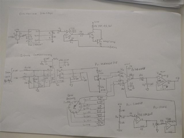
We are working with INA114. In thermal cycling @-40 degree C the output of INA is reduced form expected

We expect 2V with gain of 200. Input to INA114 is from strain guage bridge of 120 ohms. the REF pin of this IC is connected vai opa 4227 for DC offset setting

Kindly guide me 

  • Hi Smitha,

    how much is the deviation from the expected value?

    Could the deviation come from the strain gauge bridge itself? Have you already checked the performance by replacing the bridge with ultra high precision resistors?

    Are you absolutely sure that the temperature is not going below -40° during the cycling? "Ovens" used for temperature cyclng can show considerable control fluctuations.

    A schematic would be helpful.

    Kai

  • Hi Smitha,

    Please refer to the excellent comment from Kai, he asked many questions that will help us address this issue. I will add onto his response with a few questions of my own.

    What is the range of thermal cycling in your test? What is the expected vs measured value at 25°C? What is the measured value at -40°C?

    Please provide a schematic of your circuit.

    Thanks,

    Zach

  • hi Zach,

    The thermal cycling test range is +55 to -40 degree C  expected value for this range of temperature is  2V but at -40 degree C measured value  is   1.874V  but at 25 degree C the measured  value is 2V only changes we are seeing is at -40 degree.

    Hi kai,

    The expected value is 2V

    The strain guage will be sitting outside the thermal chamber which will be at room temperarture (25 degreeC) 

    i am sure that temperature inside chamber is not going below -40 degreeC

    Will be attaching the handwritten schematic which might help for better understanding. 

  • Hi Smitha,

    have you considered that trimmers can behave weird at temperatures below 0°C? The air humidity within the trimmers can freeze and by this increase the wiper contact resistance. The rotary switch may also suffer from this freezing effect.

    And I see another issue: The OPAmp arround the transistors Q1 and Q2 isn't phase lead compensated and may become instable at very low temperatures.

    Kai

  • Hi Smitha,

    Adding onto Kai's response, I notice there is another device between the strain gauge and the INA114. Is this device within the temperature chamber? Any errors caused by temperature change in the isolation device will be amplified by the INA gain of 200V/V. For this reason, the INA114 will typically be the "front-end" device that interfaces directly with the circuit. Any necessary isolation can be implemented after the gain stage as in the example shown below.

    Regards,

    Zach

  • hi zach/Kia 

    Before we planned to use ISO 124 after INA114 but there no availability of the iso124 

    Yes there is isolation device which we needed for signal isolation. i have tested  these devices  separately in -40degree C  to find out where exactly the changes has happened. Isolation amplifier works fine at -40 degree C and i am able to notice the change in INA114. Yes we have used rotary switch for gain selection but the operating temp range of rotary switch is -35 to 85 degree C also we have not seen any changes there w.r.t temperature

    but we have used resistors (RG) for gain selection near to rotary switch for gain variation. 

    I am suspecting it to be INA114 or resistors used. 

    Can you help me on this. if its INA114 what design change i have to consider. 

    planning to use NTC resistors for gain selection (RG) to rule out any issue with normal thin film resistors which is currently used for gain selection. Using NTC or PTC as gain selection resistors will there be any effect on INA114 gain BW kindly suggest 

  • Hi, Zach/Kai

    Before we planned to use ISO 124 after INA114 but there no availability of the iso124 

    Yes there is isolation device which we needed for signal isolation. i have tested  these devices  separately in -40degree C  to find out where exactly the changes has happened. Isolation amplifier works fine at -40 degree C and i am able to notice the change in INA114. Yes we have used rotary switch for gain selection but the operating temp range of rotary switch is -35 to 85 degree C also we have not seen any changes there w.r.t temperature

    but we have used resistors (RG) for gain selection near to rotary switch for gain variation. 

    I am suspecting it to be INA114 or resistors used. 

    Can you help me on this. if its INA114 what design change i have to consider. 

    planning to use NTC resistors for gain selection (RG) to rule out any issue with normal thin film resistors which is currently used for gain selection. Using NTC or PTC as gain selection resistors will there be any effect on INA114 gain BW kindly suggest 

  • Hi Smitha,

    I see another issue: C5 and C6. Are really 100nF caps mounted from the both outputs of ACPL-C79B to signal ground? This will very probably cause instability. I doubt that everything is ok in front of the INA114.

    Kai

  • Hi Smitha,

    Your schematic seems to shows OPA2228 in a buffer configuration (U3A and U3B). OPA2228 is a decompensated amplifier that is only stable in gains of 5 or greater. OPA2227 is the compensated version of this amplifier that can be used at unity gain. Can you measure the output of these amplifiers with an oscilloscope to check for oscillation? It is highly recommended to replace U3 with the compensated OPA2227 for unity-gain stability.

    Can you provide the test schematic you used when testing the INA114 at -40C without the isolation amp?

    Thanks,

    Zach

  • Hi zach,

    Thanks for your support will consider your comments

  • Hi kai everything is ok with ACPL. thanks for your support