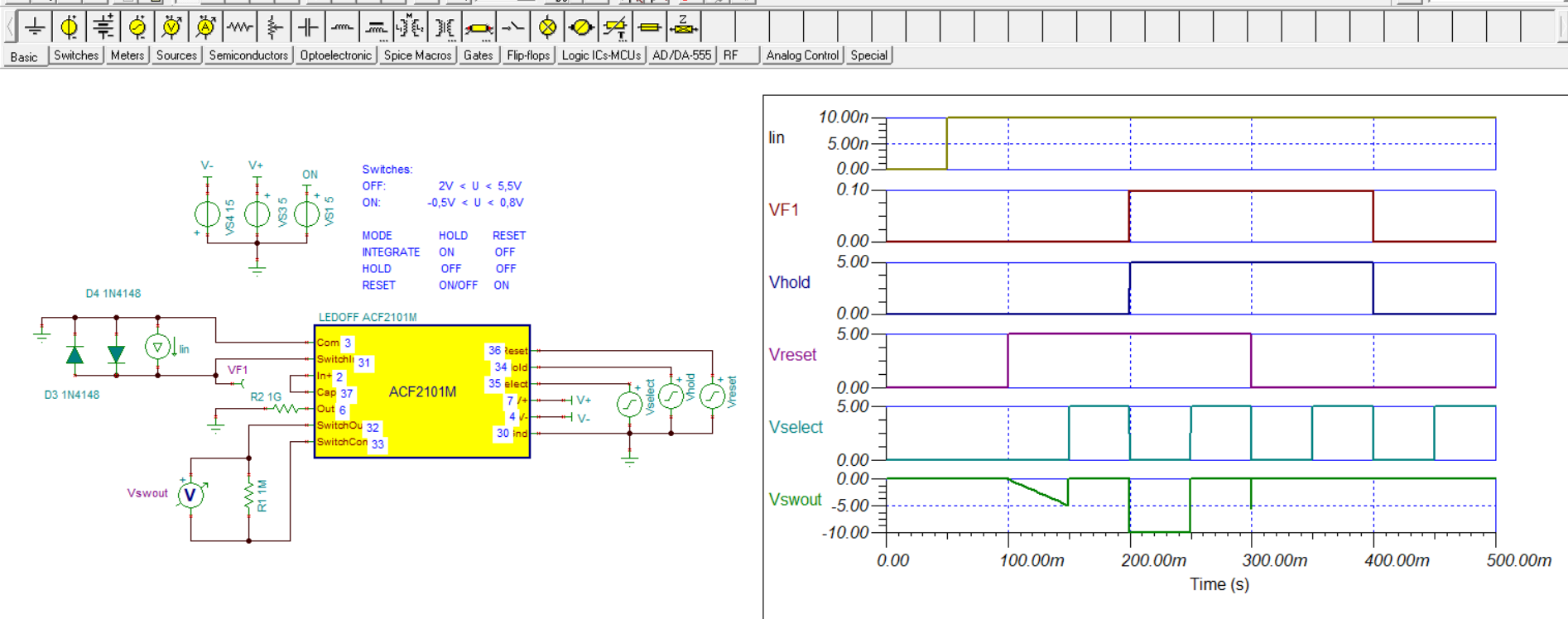
In this Simulation, Why two diodes(D4 1N4148) are connected with current source and also if i simulate without diodes why i am not get simulation result properly.
Original question:

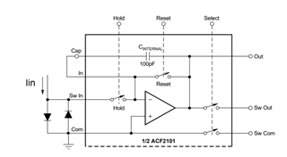
ACF2101: Can't get the Spice model to run in LTSpice as expected