This thread has been locked.

If you have a related question, please click the "Ask a related question" button in the top right corner. The newly created question will be automatically linked to this question.

AMC3302: Isolated amplifier input circuit(Re-inquiry)

Part Number: AMC3302
This is an item I inquired about three months ago.

"The input voltage specification for the AMC3302 is +/-50mV, but it is rated at +/-60mV from the shunt resistor.
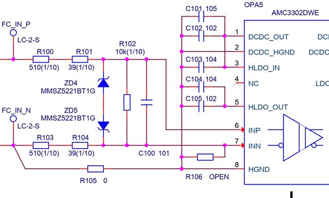
Can I input the input signal by dividing it into resistors?
Of course, I believe that a better circuit can be constructed by mounting an operational amplifier on the input section,
but I do not want to prepare a power supply on the input side (primary side).
So please let me know if there is no problem with just resistor voltage division."

As a result of experimenting with the evaluation kit, it did not work properly. I would like to get some advice on
whether the number of circuits is inappropriate.

  • Hi Yoshi,

    In what way is your setup not working? Can you describe the behavior?

    Looking at your schematic, are the second numbers the size of the capacitors? How is the input of your device? The filtering of your inputs is something I am curious about. 

    Please let me know so I can better assist. 

    Best regards,
    Eva

  • Hi Eva
    Thank you for answering.

    First, the input is to flow 6 amperes of direct current through the shunt resistor (10 milliohms).
    The problem is that even at 0 ampere, about 200mV is output from the differential output of AMC3302.
    If the current is increased, the output linearity cannot be achieved as specified.
    Is it the input bias current of AMC3302 that is the cause?
    As for the capacitor, a 100pF is installed. The frequency response can be adjusted later, so it is not important here. An important problem is the inability to obtain linearity.

    Best regards

  • Hi Yoshi,

    Thank you for explaining. 

    I think the input bias current could be a factor here. If nonlinearity is the problem you are experiencing, there are a few considerations.

    • The input source is optimized for low-impedance shunt resistors. Your shunt of 10 mOhms is probably small enough, but you could try smaller as well.
    • Temperature variance could affect nonlinearity, be sure you are within the absolute maximums.
    • Any instability or noise in power supply could cause nonlinearity as well. 

    Please let me know what you think. Additionally, if you send me some waveforms of your input and output that could better help me deduce the error source. 

    Best regards,

    Eva