This thread has been locked.

If you have a related question, please click the "Ask a related question" button in the top right corner. The newly created question will be automatically linked to this question.

INA333: EVM-Output voltage has large ripple

Part Number: INA333
Other Parts Discussed in Thread: TINA-TI

Hi,

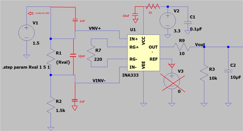
Recently, I tried few experiments by using Eval board: INAEVM-MSOP8 along with the INA333. In order to emulate the load cell (whose wheatstone bridge nominal resistance is 360 ohm) and the differential bridge voltages from load cell upto 5mV. 

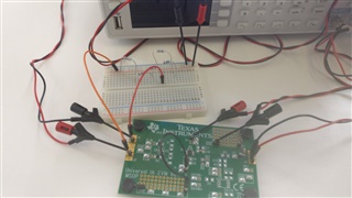
By looking at the similar question in the previous forum, I just made simple electric circuit by using the breadboard arrangement. 

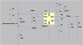
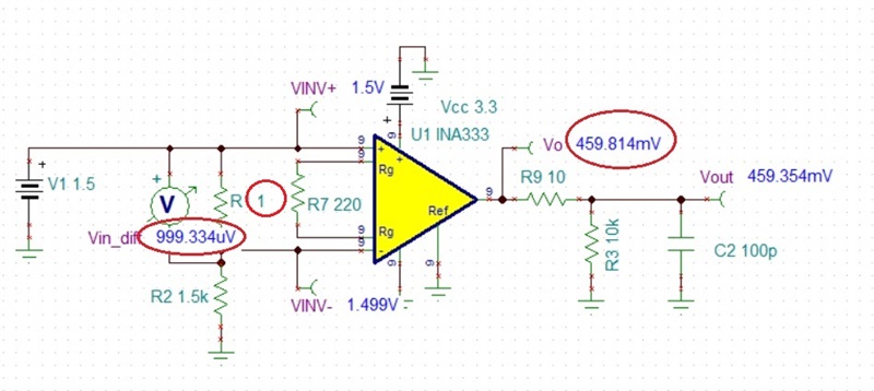
V+ = 3.3V, V- = GND, Vref =GND, Gain = 455
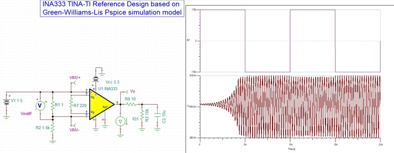
Schematic:

Breadboard arrangement:

Just to emulate the 1mV to 4mV small signals, I placed four 1 Ohm resistors in series with the 1.5kOhm. 

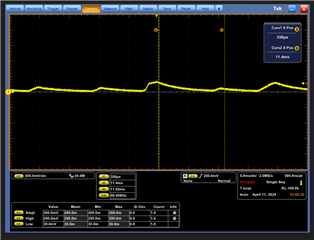
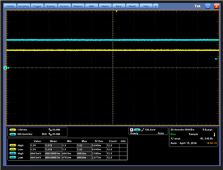
For the 1.086 mV signal across 1 Ohm resistor is connected between V+IN and V-IN. Theory Vout = Gain*Vdiff = 1.086 mV* 455 = 494.13 mV DC

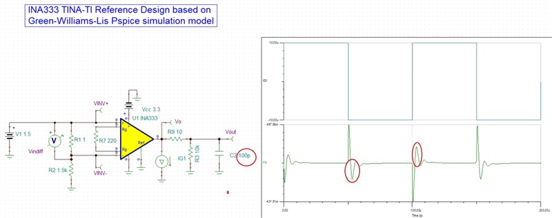
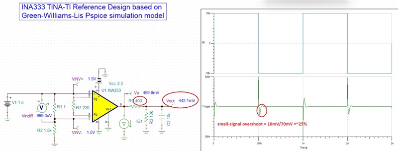
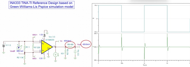
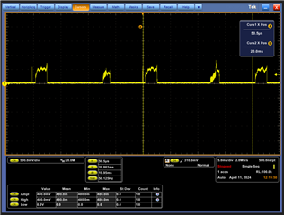
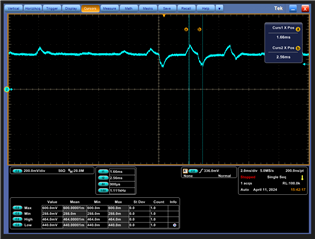
But observe the following oscillating  Vout result from Oscilloscope

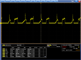
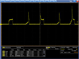
For 2.26mV input signal, the observed oscilloscope- Oscillating Vout result 

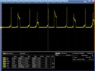
Could you please let me know if I require any better schematic or by improving the measurement methods to get smooth DC Vout signal from Oscilloscope?

Thanks & Regards,

Sairam

  • Sairam,

    Before I address the actual cause of the problem, please note that across 1 ohm shunt resistor the Vin_diff is 999uV [1.5V*(1ohm/1501ohm)] and not 1.086mV. 

    Thus, in theory Vout=Gain*Vin_diff = 455.5*0.999 mV=455mV.  The 459.8mV shows in simulation below due to additional 10uV offset voltage:Vout=455.5*1.009mV=~459.6mV

    Now, back to the problem - the issue you see is caused by the instability of your circuit application. INA333 is a macro-power instrumentation amplifier that cannot drive 10uF. 

    A series output resistor, R9, helps but 10ohm is far too small to make a difference - see below transient stability simulation showing sustained oscillation.

     .

    With R9 of 10ohm, all INA333 can drive is 100pF - see below (recommended small-signal overshoot of less than 25%).

    It would take R9 of 400ohm to make the circuit stable with recommended overshoot of 25%.  However, this would cause a large error at Vout - 442mV vs 459mV - see below.

    Thus, I order to eliminate the Vout error, R9 would need to be moved after R3 load - see below.

    Below I have attached Tina-TI transient simulation file. You may download the free version of Tina-TI using following link: https://www.ti.com/tool/TINA-TI

    Sairam INA333 Transient Stability Circuit.TSC

  • Hi Marek,

    Thanks for your answer and the simulation file.

    I made the changes R3 10k, R9 400 & one time C2 100pF

    The observed oscilloscope as below

    Here I guess there is a influence from 230VAC 50Hz as Radiation EMI on the Vout signal that could be reason for the Vout oscillating wave signal. Or any other reason are you expecting?

    Could you let me know how can we get the Vout as a constant DC signal?

    Other experiment with the arrangement of  R3 10k, R9 400 &  C2 10µF

    The observed oscilloscope as below

    Almost smoothen the signal, but reduces the Amplitude to 260 mV which is much less than the theory value.

    Thanks & Regards,

    Sairam


  • Now I used Isolation transformer to connect power supply to the Oscilloscope connection, by using that 50Hz Conducted EMI is almost removed.

    The observed below result is

  • This does look like 50Hz EMI signal. Are you somehow connected to 230AC, are close to other equipment powered from it, or using switching power supply? If so, perhaps you should try to use a linear supply or battery. The low pass filter at the output, 400ohm||10uF, has a corner frequency of 40Hz so it helps but does not remove all interfering signal because it is too close to 50Hz. How about trying to add 1k||10uF (if possible) on the supply pin to see if this is the path interference enters the signal path. Below please find few additional suggestions to trouble shoot the problem.

  • Hi Marek,

    Thanks for your suggestion. By using linear power regulator the Vout is stable

    Channel 1 : 1.5 VDC, Channel 2: Vout =Approx. 484 mV

    Thanks for your support.

  • Good to know the problem has been fixed.  Please let us know if you need further assistance.