This thread has been locked.

If you have a related question, please click the "Ask a related question" button in the top right corner. The newly created question will be automatically linked to this question.

LM7322: Operation condition for a MOSFET driver application

Part Number: LM7322
Other Parts Discussed in Thread: OPA2994

Sir

We are planning to use the LM7322 to drive a MOSFET.

The operation condition is listed as follows

VS = + - 15V (Dual power supply)

VO = VGS = 2 ~ 3V

MOSFET = AOD496, Ciss = 1200pF_Max (as datasheet)

No resistive load connected at the output

Is it any risky to permanently destroy according to power dissipation across the output stage?

Regards

Ben

  • Hi Ben,

    Nothing that you have described suggests there's any risk to the op amp from this circuit design. We can help review the design as you get further along to see if there is any further potential concerns in the design. 

    I will add that we have a new unlimited capacitive load driving op amp that just came out called the OPA2994 that I would highly recommend taking a look at it as it has improved performance over the LM7322. 

    The Voltage-to-current (V-I) converter circuit with MOSFET piece of content goes over this in more detail in case you want to learn more. 

    Best Regards,

    Robert Clifton 

  • Hi Robert 

    Thanks for the information!

    Please refer to the attachment for our existing design.

    We are now planning to extend the supply voltage up to + - 15V to compensate for the loss according to the heavy resistive load R9 = 50 ohm

    Could you please help to review our intention in your expert opinion?

    Any comment is welcome!

    MOSFET Driver Evaluation 20240507.pptx

    Regards

    Ben

  • Hi Ben,

    I really appreciate you sharing your design early in development. I rather review potential problems earlier than have to help debug and fix later. 

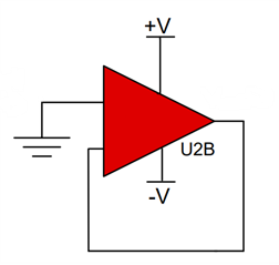
    My first comment is channel B. It looks like it's not planned to be used. I'd recommend using a single channel variant, but I understand there's reasons why you would want to continue using the dual channel and just not utilize the second channel. I recommend for the unused channel to set it up where in noninverting input to ground and connect the inverting input and output together as shown below: 

    We have a piece of content, How to Properly Configure Unused Operational Amplifiers, that can explain in more depth why you want to set the op amp like this. 

    As for the other channel, I didn't see any potential red flags in that design.

    Best Regards,

    Robert Clifton