This thread has been locked.

If you have a related question, please click the "Ask a related question" button in the top right corner. The newly created question will be automatically linked to this question.

XTR116: TPS54062

Part Number: XTR116
Other Parts Discussed in Thread: XTR117, TPS54062

Tool/software:

Hello,

I changed my design to the following:
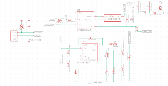
The problem now is that the switch output is ~68mA instead of 20mA and C11 burns through. Could it be that the split gnds (Float Gnd and LOOP gnd) are not correct? or what could be the problem?

I use the XTR117 and TPS  and would like a 2-wire transmitter 4-20mA.

  • Why is there the TPS54062? In a 2-wire loop, it is not possible to have sensor that draws more than 4 mA. (And for a sensor that does not need more than 4 mA, the XTR117's internal LDO suffices.)

  • Hello,

    It seems if you are destroying C11, there must be some problem with the DC/DC converter.  Can you test the DC/DC with the XTR removed from the loop to verify its functionality first?  Can you verify there is no load on the DC/DC converter?

    Also, along with Clemens' point, there is a minimal amount of power that can be consumed in order for the XTR to maintain accuracy - the total Iq of all devices on the line need to be less than 4 mA.  I see you have picked a low-power DC/DC, so it seems that it should work, but the load on the output of the DC/DC will increase the total current consumption.

    This thread has gone to the team that supports the XTR, so we don't have much additional information on the DC/DC converter.  If it does seem like a problem with the way the DC/DC is configured then we can move it over to their forum, but I'd like to make sure that is the case first.

    Regards,
    Mike