A related question is a question created from another question. When the related question is created, it will be automatically linked to the original question.
If you have a related question, please click the "Ask a related question" button in the top right corner. The newly created question will be automatically linked to this question.
The XTR117 is designed for a 2-wire loop, where the measurement circuit is powered from the loop, and floating. Is this the case in your application, or do you have a separate power supply?
Where does that 20 V signal come from, and what are its characteristics? The XTR117 has a built-in 5 V LDO; if you need a higher voltage, you can connect your own regulator between V+ and IRET. Alternatively, divide down the input signal so that it can be handled with a 5 V circuit.
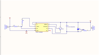
The 20v signal comes from an electric motor sensor output, it is supposed to connect to the PLC, so the PLC has 4-20mA input, while the motor measurement is 0-20v, there is no any separate power supply at the motor side. I have a schematic, but I don't know how to upload it.
So the motor and the PLC use the same supplies (or at least the same GND)? And there is a 24 V supply available for your circuit? The XTR111 would be a better choice. (Its input should be below 12 V, so you should divide down the signal.)
To upload the schematic, make a screenshot, save it to a file, and use the "Insert" / "Image" menu below the text box. If the entire schematic can be put on a public forum, you can insert the .pdf directly.
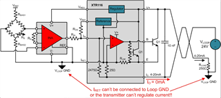
The sensor and driving circuit producing the signal driving the XTR117 must be referred to the local current transmitter GND (IRET) and IRET needs to be allowed to float and isolated from the 4-20mA loop supply GND. Also, the overall current consumption of the XTR117 current transmitter + driving circuitry must not exceed 4mA.
If your 0-20V signal source is referred to the loop GND and it is not isolated, this will not work with the 2-wire current transmitter.
The figure below shows the 2-wire transmitter (XTR116) with IRETincorrectly shorted to VLOOPGND.
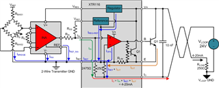
The figure below shows the 2-wire transmitter (XTR116) with IRET correctly connected, where IRET is allowed to float with respect to VLOOPGND.
This is explained in detail on the blog series below:
Your schematic shows IRET connected to GND. If your signal source is not isolated from the loop supply, please consider instead the XTR111 which is a 3-wire current transmitter. On 3-wire current transmitter, the sensor and driver circuit of the XTR111 can be referred to the 4-20mA loop supply GND without issues.
Please also refer to the links below for more information on 2-wire and 3-wire current transmitters.
Please ensure that the circuit on the sensor output producing the 0-20V signal is completely isolated from the loop supply ground.
One of the most common issues with 2-wire current transmitters occur because circuit designers do not consider the current path to earth GND, or in other words, the chassis GND leakage paths back to the loop supply GND from the sensor circuit. If the (motor) sensor local GND and 4-20mA current loop grounds are not completely isolated, and if you must use a 2-wire current transmitter, you will have to find a way to isolate the sensor circuit from the 4-20mA ground. One common method is to convert the voltage output to a PWM using a controller and a digital isolator.
Alternatively, if the 4-20mA loop ground and sensor output GNDs are not isolated, you may consider a 3-wire current transmitter will allow you to refer the sensor output GND and loop supply GND to the same potential without any issues.