This thread has been locked.
If you have a related question, please click the "Ask a related question" button in the top right corner. The newly created question will be automatically linked to this question.
Good morning,
I am working with INA 128 for a project and I am actually testing the amplifier responsivity to the signals I will acquire with a temperature sensor.
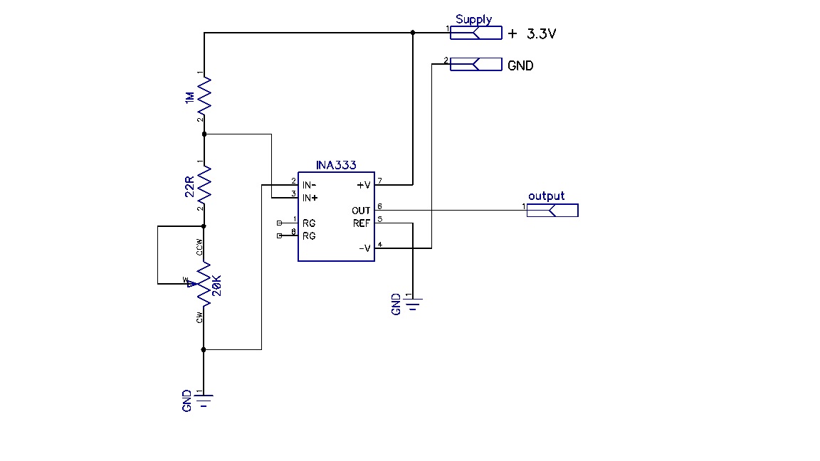
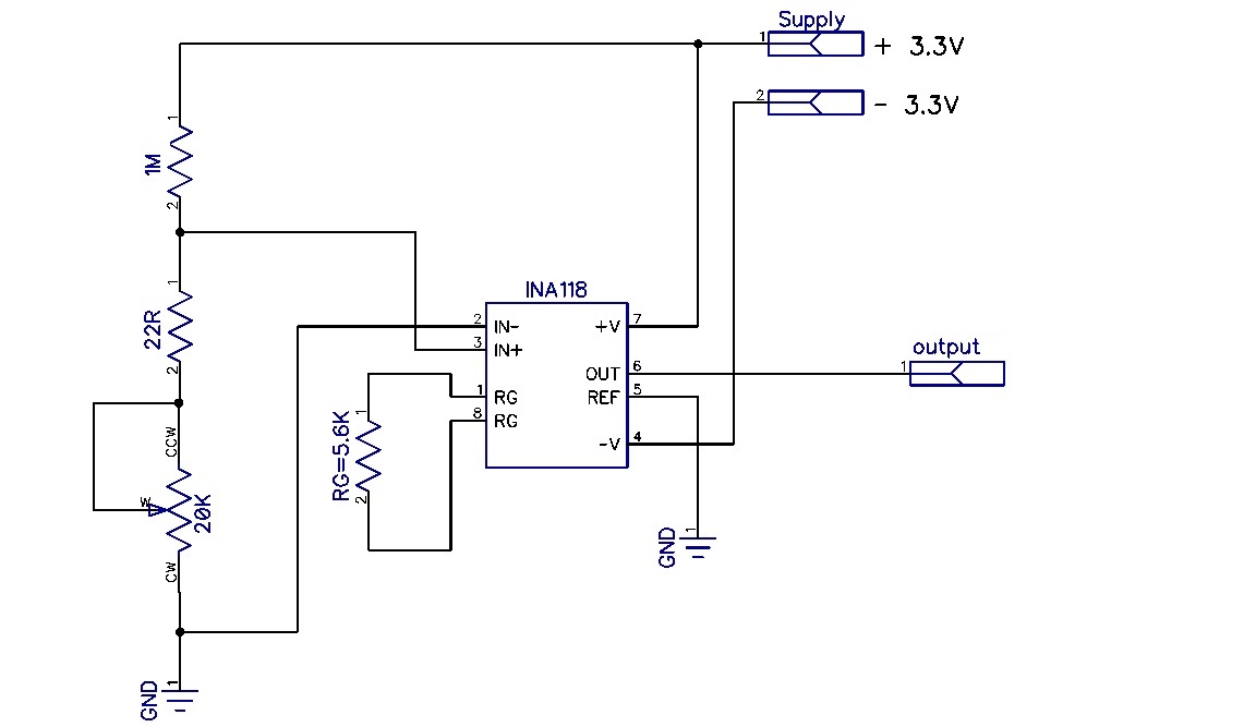
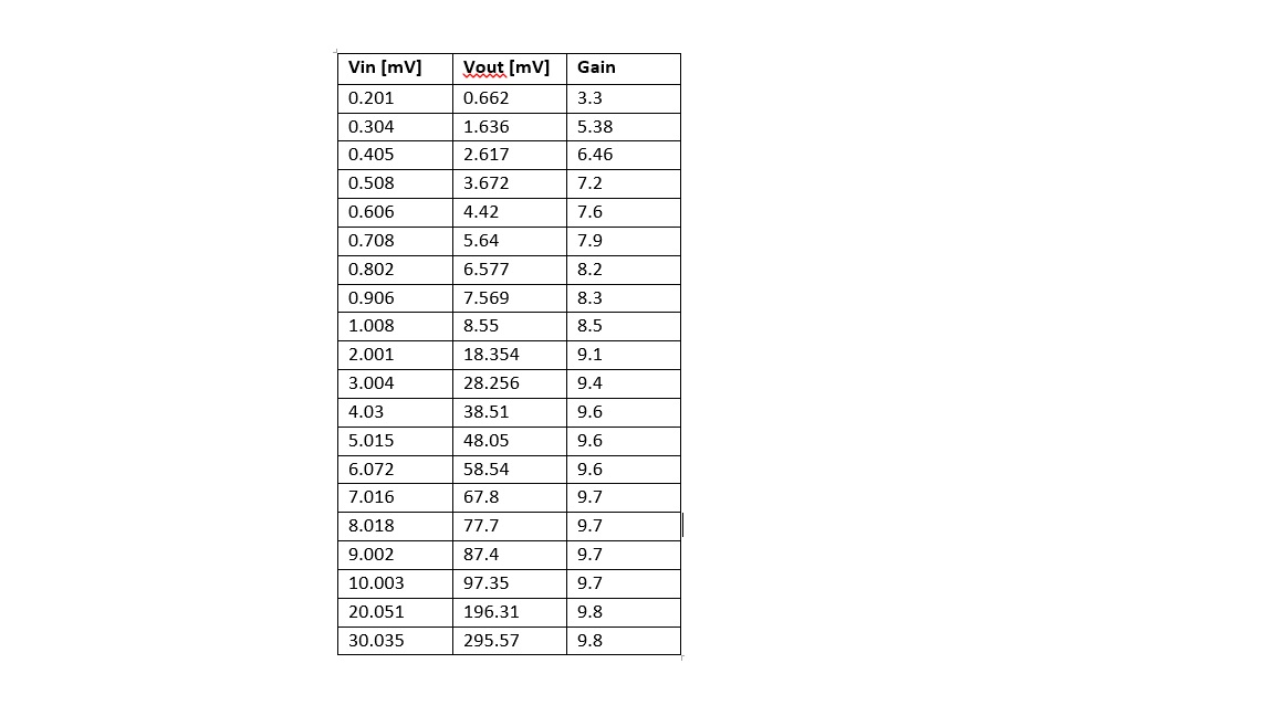
The temperature sensor is a prototype and it is basically a full Wheatstone bridge and its outputs range is from 700µV to 7mV. To be sure of the INA performances, the amplifier has been tested separately from the sensor. At INA inputs I have applied signals from 100µV to 20mV using a voltage divider, as shown beow.
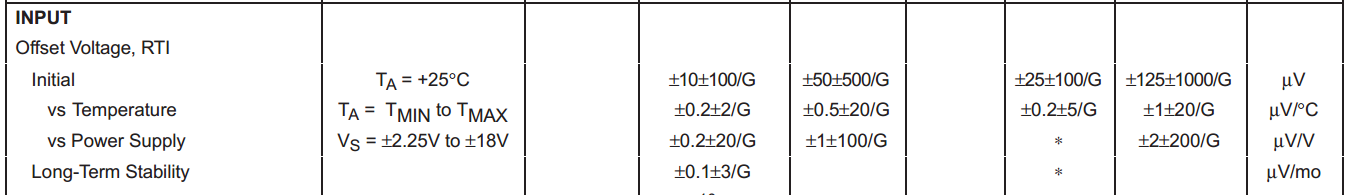
Looking to the table below, it is clear the gain is not stable.
Vin [mV] |
Vout [mV] |
Gain |
0.105 |
0.873 |
8.3 |
0.201 |
1.877 |
9.3 |
0.305 |
2.899 |
9.5 |
0.406 |
3.903 |
9.6 |
0.506 |
4.886 |
9.6 |
0.603 |
5.863 |
9.7 |
0.706 |
6.876 |
9.7 |
0.805 |
7.841 |
9.7 |
0.910 |
8.861 |
9.7 |
1.008 |
9.854 |
9.8 |
1.506 |
14.75 |
9.8 |
2.005 |
19.75 |
9.8 |
2.5 |
24.68 |
9.9 |
3.001 |
29.64 |
9.9 |
3.505 |
34.65 |
9.9 |
4.058 |
40.16 |
9.9 |
5.008 |
49.55 |
9.9 |
6.018 |
59.55 |
9.9 |
7.043 |
69.73 |
9.9 |
8.071 |
79.88 |
9.9 |
9.137 |
90.54 |
9.9 |
10.10 |
100.18 |
9.9 |
15.057 |
149.25 |
9.9 |
20.023 |
198.64 |
9.9 |
I can expect this for the lowest inputs, because I made the amplifier work out of the input range specifications, but I don’t explain the behavior for the higher values.
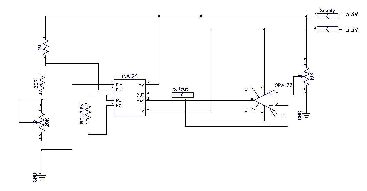
Then, I tried the following circuit for trimming the output offset voltage.
I can measure a constant gain only adjusting the output values via the potentiometer on pin 3 of OPA177. I was wondering if anyone knows a better and more practical solution to guarantee a constant gain.
Thanks in advance,
Mia
Mia,
I'm unable to view the schematics you have attached, would you please try re-posting them? The gain of the INA128 is actually not changing, I suspect that the input offset voltage of the INA128 is actually causing this issue. All amplifiers have some level of offset voltage, normally referenced to the input. In your case it would appear that the input offset voltage of your specific INA128 is about -16.65 uV. For example, consider that the gain of the INA128 is in actuality 9.9, with a -16.65uV offset the output of the amplifier for an input signal of 105uV will be (105uV - 16.65uV) * 9.9 = 875uV which is extremely close to the value that you measured. As the input signal increases, the effect of this input voltage decreases, which is why it is essentially immeasurable at the 20mV input signal level.
Note that 16.65uV is an extremely low input offset voltage for an instrumentation amplifier. Looking at the INA128 datasheet, the initial offset could be as high as 100uV for the high grade version in a gain of 10:
As you've found, you can "null" this offset voltage at the reference pin. One other option is to perform a calibration by shorting the inputs together (Vin = 0V) and measuring the offset voltage, then subtracting this value from all subsequent measurements. Many precision systems calibrate for initial offsets as well as the change in offset over temperature (known as drift). Another option is to chose an instrumentation amplifier with a lower initial offset value, two such options are the INA333 and INA118. A programmable gain amplifier such as the PGA280 or PGA281 would also provide greatly reduced offset.
John,
Thanks for your reply.
Please, find attached the two schematics related to INA128 configuration and the trimming offset voltage circuit. I think something doesn't work at the first try.
I will calibrate the INA128 as you have suggested. Then, I will perform the same kind of tests with INA333 and I will compare the results with the ones I got from INA128.
Best regards,
Mia
Mia,
Using a 10k potentiometer in your trim circuit will most likely not provide the required resolution for you to cancel such small an offset. I would recommend using fixed resistors of equal value, and a much smaller potentiometer. Also, with your circuit configured as shown, you will only be able to cancel a negative offset voltage. If you are building multiples of this circuit, some INA128s may exhibit a positive offset, and others a negative offset. Therefore, it may be more flexible if your trim resistors are between the supplies, allowing you to produce a positive or negative voltage to cancel the offset.
Is it right keeping a constant Vref for all the measurements? At higher values of Vin, this solution seems less consistent.
I had a look to the INA118 specifications, it has the same Offset voltage of INA128, it should behave better because of the lower quiescent current?
Then, I have performed some tests with INA333 using the following configuration.
I didn’t get good results. Could you, please suggest me an equivalent one in SOIC or DIP packaging?
Thanks in advance,
Mia
Mia,
The typical offset value of the INA118PB/UB is +/- 10 +/1 50/G uV compared to +/-10 +/- 100/G uV for the INA128 which is why I suggested the INA118 as a possible replacement. Quiescent current is not relevant here.
You're circuit with the INA333 will be inferior to the previous versions because you are operating the part on a single supply. Therefore your input common-mode is at the negative power supply rail and the input offset voltage of the part will increase. Input offset voltage is minimized with the input common mode voltage at the mid-point between the power supplies (1.65V in a 3.3V system). Operating the INA333 on +/-2.5V would improve the performance.
You're calibration will be less accurate at higher input voltages because your source impedance is increasing for these higher voltages. Therefore the error voltage produced by the input bias current of the instrumentation amplifier increases for increasing voltages. In your final system, will the source impedance change with voltage?
In my previous post I suggested using two discrete resistors in combination with the potentiometer to null the offset. Here is an example:
R1 and R2 will need to be matched very closely and potentiometer P1 should be a multi-turn trimmer type for fine adjustment. Another option would be to use a high-resolution D/A converter to provide the offset correction voltage, or to simple subtract the offset from the measured results in software.
John,
Thanks for your detailed and helpful reply.
I have performed some tests and hereby the results:
The results are not better as I expected. I was wondering if I made something wrong.
For the source impedance, you confirmed my impression. I haven’t finished the tests on the sensor prototype so I can’t say for sure the source impedance will change, but I guess it will.
If I perform the measurements after the calibration of INA128 and I got the following surprising results….why this circuit doesn’t achieve the goal of having a stable gain?
Do you think there should be any better solutions to solve this problem?
Thanks in advance,
Mia Magnalardo