Because of the holidays, TI E2E™ design support forum responses will be delayed from Dec. 25 through Jan. 2. Thank you for your patience.

This thread has been locked.

If you have a related question, please click the "Ask a related question" button in the top right corner. The newly created question will be automatically linked to this question.

XTR116 PIC18F46K22 DAC

Other Parts Discussed in Thread: XTR116, XTR111, XTR115

Hi everyone,

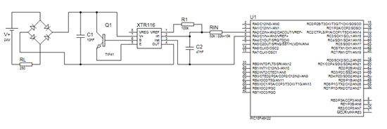
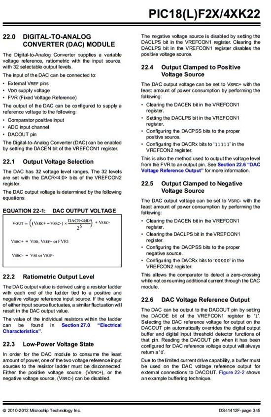
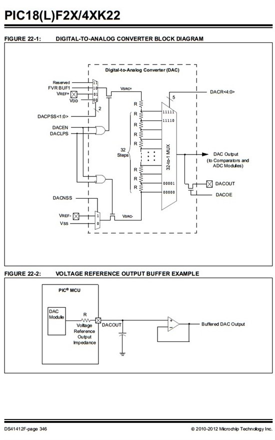
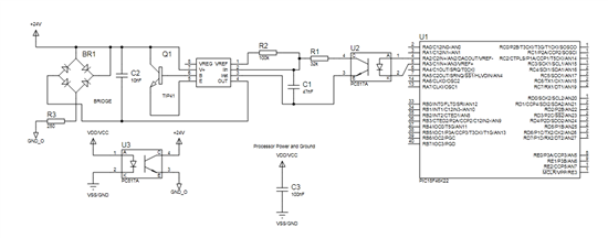
XTR116 integrate , I would like to include in my circuit. My processor is 18f46k22. I'm gonna use the DAC pin of the processor. I made a connection like that in the picture. Is this correct ? Wrong is what should I do? Thank u very much..


  • Hello User,

    We'll need to read through the PIC datasheet to understand if it will properly interact with the XTR116. 

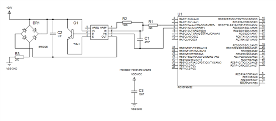
    While we're reviewing the MCU, please provide a more complete schematic of the PIC that shows how you intend to power the VCC/GND pins of the PIC microcontroller.

    Since this is a 2-wire transmitter grounding issues are a concern if the microcontroller is not completely powered and referenced between the VREG and IRET pins of the XTR116. 

  • Hi Collin, Thank u for answer.

    I share the schematic representation of the power and ground. 

    This circuit XTR I will include the integrated circuit.

  • Hello,

    I have the same concerns with this design as I did with the design in the link below:

    http://e2e.ti.com/support/amplifiers/precision_amplifiers/f/14/p/376041/1327970.aspx#1327970

    If you want to use an MCU/DAC that is not powered from the VREG/IRET regulator in the XTR115 to set the output current of an XTR device, then you should really be using a 3-wire transmitter like the XTR111. 

    The XTR115/116 will not work if you try to use a DAC that is powered from another supply to control it because you will create grounding issues and the currents won't properly flow.  If you do power the MCU/DAC from the XTR116 VREG/IRET regulator, then you'll also have to make sure that the circuityr doesn't draw more than ~3.5mA of current or the XTR will not be able to output the low-level of 4mA properly.


  • Ok. But currently I don't have XTR111.  I used optocoupler ends problem ? I'm trying to make it look like the links.

    "http://www.mikroe.com/downloads/get/1905/4-20ma_click_manual.pdf"

    Is that how it works ?

  • Hello,

    This will not work as you've drawn it as you are improperly using the optocouplers.  There is a full schematic provided in the design you sent, have you tried implementing circuitry that more closely resembles the one shown in the design? 

    Notice that the DAC and ISO devices are powered from the VREG (VCC_ISO) output referenced to IRET (GND_ISO) of the XTR116. 

    So if you wanted to construct something similar with TI components, consider using an ISO76xx isolator and an DAC73xx DAC.

  • I'm sorry. I can not share all of the Company for that project. How do I make these measurements otherwise withoutan external DAC ?(with xtr116).  I would like to add a circuit to measure the current in the load. Thankk u for interest.