This thread has been locked.

If you have a related question, please click the "Ask a related question" button in the top right corner. The newly created question will be automatically linked to this question.

TINA/Spice/OPA2189: OPA2189 BPF design

Part Number: OPA2189
Other Parts Discussed in Thread: TINA-TI, BUF634, , INA1620, TLV2422, RC4558, OPA1678

Tool/software: TINA-TI or Spice Models

Hi Sir,

The following are BPF requirements and please provide TINA simulation. Thank you.

1. 25KHz BPF

-opamp power supply 5/-5V or +15/-15V

-input 5V 25KHz square wave

-BPF BW: 1KHz 

-filter order: 8

-ripple: 1dB

-stopband attenuation: -35dB at least

-25KHz phase: 0 degree

2. 60Hz BPF

-opamp power supply 5/-5V or +20/-20V

-input 5V 60Hz square wave

-BPF BW: 20Hz 

-filter order: 8

-ripple: 1dB

-stopband attenuation: -35dB at least

-60Hz phase: 0 degree

  • Hi Tseng,

    do you have a schematic?

    Kai
  • webench_design_4592932_12.tscHi Kai,

    The phase of using webench  for BPF 25KHz is 0 degree, but import to TINA-T finds phase has shift, not 0 degree

  • Hello Tseng,

    It is normal for a simple op amp amplifier circuit, or a circuit as complex as an active filter, to incur non-zero phase shift at all but dc. Even at the lowest of frequencies there may be a fraction of a degree of phase shift occurring from input to output. Therefore, it is not practical to expect an active filter to have 0 degrees of phase shift at a specific frequency unless you are dealing with a special class of filters called All-pass filters. They are different in that they are designed for specific phase shift, or time delay characteristics, but they have nearly flat amplitude response over most of their usable frequency range. They can't provide the low-pass, band-pass, etc. responses that filters are most commonly used to provide.

    Note in your TINA circuit that you are specifying the BUF634 in the multiple-feedback active filter stages. The BUF634 has a gain of less than 1 V/V, and is intended to be employed with an op amp to provided higher output current than can be obtained from an op amps alone. Thus, operational amplifiers having high open-loop-gain and appropriate bandwidth must be employed in the active filter stages. The OPA2189 titled in this e2e is an example of an op amp usable in an active filter.

    Regards, Thomas Precision Amplifiers Applications Engineering

  • Yes Tseng, this seems like a very aggressive filter Q wise in the stages. You might consider an extremely capable topology shown in this tread - also, why use a precision amp like the OPA2189 when BP filters are by definition AC coupled? What do you think your highest Q stage is - if over 10, you have will production problems. And, as Tom says, MFB filters need to implemented with a VFA op amp, not a buffer like the BUF634 - did the webench tool deliver with that device?

    e2e.ti.com/.../788559

  • Hi sir,

    Yes, BUF634 is recommended by webench. I just type BP filter parameters as I mentioned to webench. Anyway, can you teach me how to design 8 order BP filter base on webench?

  • Hi Tseng,

    using a 8.th order bandpass filter sounds rather unrealistic, because you would need extreme precise filtering components showing extreme little temperature drift and extreme little long term drift. You should size down the filter requirements to the absolute minimum and then look for a suited circuit. Or you could look for a different topology like using the powerful lock-in amplifier technique.

    Kai
  • Hello Tseng,

    It is unfortunate that the filter tool directed you to the BUF634; that is an error. If you are using the New TI Filter Design Tool, it is a beta version of the program and the "bugs" are still being discovered. Hopefully, by time the beta testing time is complete the Webench team will have the bugs cleared out.

    Often, an 8th-order filter is difficult to realize based on the passive component tolerance issues that Kai pointed out. About the best tolerances components that are available within reason from distributors are 0.1% resistors, and 1 % capacitors. Even with components having those tolerances a practical filter may still have a somewhat distorted response from the ideal. Lower tolerance components may be available, but their costs become too expensive for many applications.

    I suggest for now that you consider using an older TI filter tool, FilterPro. It is easy to use and doesn't make any op amp suggestions. However, it does provide a key op amp parameter "Minimum GBW (Gain Bandwidth) reqd" in the filter design results. Having that minimum GBW allows one to select op amps from the TI amplifiers web pages that will have sufficient bandwidth to support the specific filter response. You find the GBW listed on the final FilterPro schematic screen by scrolling the filter's schematic image upwards.

    You can access and download TI's FilterPro v3.1 here:

    http://www.ti.com/design-tools/signal-chain-design/webench-filters.html

    There used to be some training materials for FilterPro on line, but it looks like they have all been removed. That shouldn't be a problem because the application of FilterPro is very straightforward. If you are really serious about synthesizing an 8th-order bandpass response, just check the "Optional - Filter Order" box to "8" and progress through the screens in FilterPro.

    Regards, Thomas

    Precision 

  • Hey tom,

    I tried that link and I don't think it takes you to the older Filterpro tool. It takes you to the new front end GUI for filter design selection. I do have the old Filterpro which is super useful for common filter stage designs Q and Fo. But it always way overestimated the required GBP.

    I also alerted the team the BUF634 should not be in these solutions - all BUF parts will be removed.

    Also, for the highly selective BP implied here, why not try that Ackerberg-Mossberg topology in this recent thread - I was amazed how well it worked and how low the spread was in MonteCarlo.

    https://e2e.ti.com/support/amplifiers/f/14/t/788559

    Can you point to an actual orderable 0.1% low cost R?

  • Hi Michael,

    we use the ERA3A from Panasonic or the Susumu series:

    eu.mouser.com/.../N-7h7yuZ1yzvvqx

    Kai
  • Thanks Kai, yea those look to be about $0.04 in 5k pieces.

    That is still a little high for a filter I think, in that series, Mouser does not show a 0.25%, but at 0.5% it drops to $0.015 in 5k - I think I would stay with 0.5% on the R's for now for MonteCarlo purposes.
  • Hi Michael,

    If you scan down the FilterPro page you find a line that lists:

    Download FilterPro v3.1

    Following the screens it has you log in and eventually you come to:

    I didn't reload FilterPro V3.1 because I already have it on my machine.

    Yes, the GBW calculation in FilterPro and the other TI active filter programs is in some cases are very conservative, but that is intentional. Certainly, a highly knowledgeable filter designer can use advanced methods to more precisely determine the minimum op amp GBW required to provide accurate filter responses.  However, for most users providing a conservative GBW assures that they will be able to successfully obtain the desired response while investing minimal solution time.

    Indeed there are more sophisticated active topologies requiring more then one op amp per stage, that easily achieve the response needed for high-Q band-pass filters. It looks like the Ackerberg-Mossberg topology requires 3 op amps per stage, or 12 total for the 8th-order response. One of my favorites is the Dual-amplifier band-pass (DABP) discussed in the Williams "Electronic Filter Design Handbook." I have recommended that topology a couple of times here on the our amplifiers e2e forum. It is a high-performance band-pass filter topology that requires two op amps per filter stage.

    I suppose "low-cost" is a relative term, and I do tend to look at the cost in relation to what one paid for a similar component just a decade ago. Here's an example of a 1 kilohm, 0.1%, 25 ppm thin-film resistor from Mouser:

    https://www.mouser.com/ProductDetail/IRC-TT-Electronics/PCF-W0603LF-03-1001-B-P-LT?qs=sGAEpiMZZMu61qfTUdNhG1Flup5Au%252BywTu6ghkpJc0Y%3D

    There may be lower cost options out there.

    Regards, Thomas

    Precision Amplifiers Applications Engineering

  • Yes that is a good one too, but say you need 3 in the MFB LP, now you are looking at $0.18 for the R's at 5k pricing.

    The GBP margin is partially judgement call, working mainly in higher speed, Filterpro was regularly asking for >1Ghz GBP. That then gets into real cost and power penalties for its conservative approach - working mainly in the 1kHz reason, sure more margin does't hurt you necessarily.
  • Hi Sir,

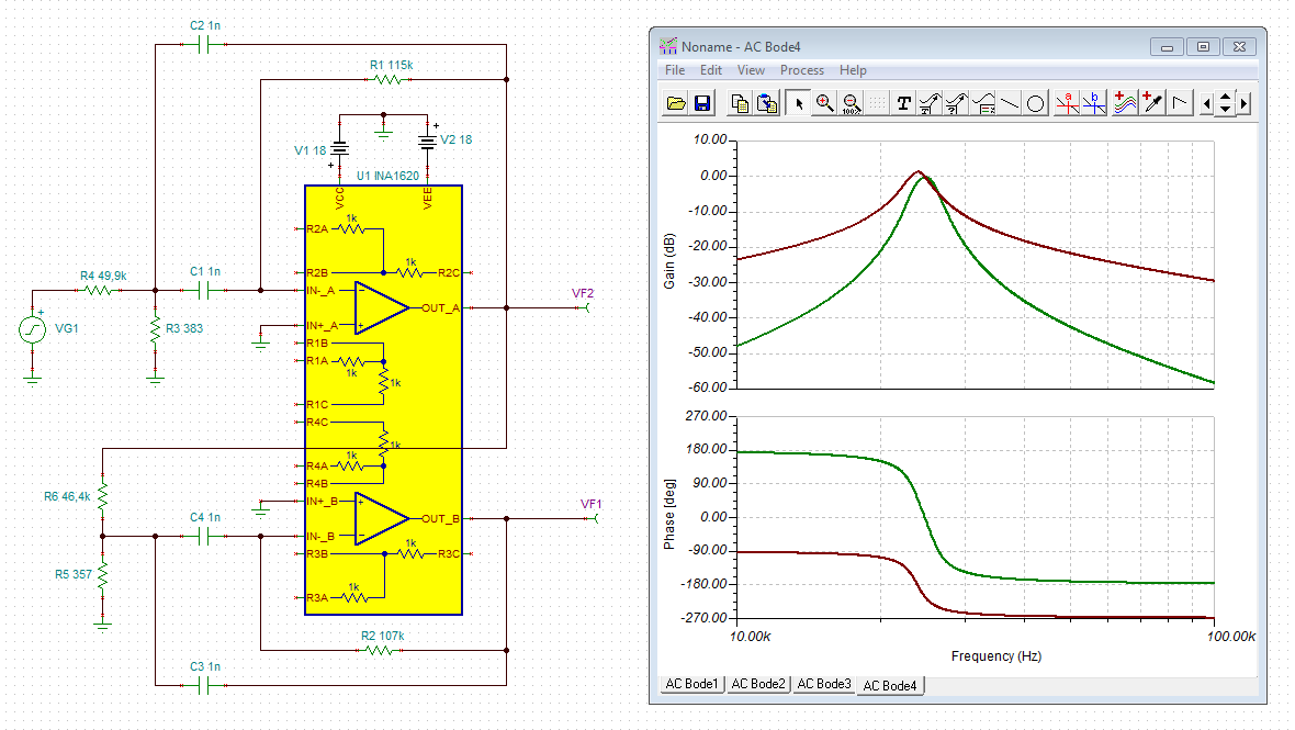
    Use webench to design the 4th BP filter, which recommends using INA1620, but it does not have library in TINA-TI.

    Can you suggest the right product according to the attached file? Thank you.

    TINA-TI's Version 9.3.200.277


    filter-design-report-20 (1).pdf

  • Hi Tseng,

    you will find the TINA-TI reference design on the product page:

    I have run the simulation for you:

    tseng.TSC

    Kai

  • Hi Tseng,

    you might also want to read this thread:

    e2e.ti.com/.../768679

    Kai
  • Yes Kai, that was a really interesting thread - I saw where Paul was suggesting a +/-30% GBP spread. For parts that have trimmed supply currents (like all of the recent higher speed parts) I use +/-15% on the GBP spread.

    In any case, on this thread that INA suggestion out of Webench is a odd - normally you would just use a dual op amp.

    I cranked out a design jumping between several different tools - I actually have had very little BP active filter experience, so a lot of this is new to me - a lot of LP however, - just for curiosity, I will see what a single stage Ackerberg-Mossberg design will give me here. My Filterpro seems to have stopped working, so I could not use it for the design - and the webench results seem a 1/2 bubble off.

    25kHz 4th order BP suggestions initial MFB.docx

    TLC2272 25kHz BP 4th order.TSC

  • I was using Selguide to find a 5MHz part, but I just noticed this TLV2422 has almost no slew rate, I wonder what a higher slew rate comparable part might be?

    So lets test needs here, assume on +/-5V supplies we asked for 8V output swing at 25kHz - that would be 0.6V/usec, far exceeding the amazingly low 0.01V/usec in this low power part - might need more for implementation.
  • So I do have this working with the AckerbergMossberg topology. Each 3 amplifier stage is a two pole BP where the apparent advantage of the design is you have independent control over the Q and gain once you set the RC to give you the center frequency - and that is true, that works really well. But for a 4th order, you would need 6 op amps. I did set it for much lower output noise than the more standard MFB I sent out earlier, and it may have lower spread to component tolerances - will take a while to work through that. I get the feeling this topology was more suited IC development. But it is interesting how easy it is to tune in.

    I will take a look at the Dual Amplifier BandPass as well - new for me also.
  • Hi Michael,

    Here is the link to the recent e2e thread where I provided information about the Dual amplifier band-pass (DABP) filter:

    The Electronic Filter Design Handbook is where I originally found the topology. Arthur B. Williams, the handbook author, provided a reference to the original article, Sedra, A. S., and Espinoza, J. L. "Sensitivity and Frequency Limitations of Biquadratic Active Filters," IEEE Transactions on Circuits and Systems, Vol. CAS-22, No. 2, February 1975.

    Regards, Thomas

    Precision Amplifiers Applications Engineering

  • Some results with the AckerbergMossberg approach.

    the app note was aimed at other things, some of which did not seem to matter on just a basic filter - so the circuit simplifies a little.

    Briefly, the 1/RC with all those equal R and C sets F0

    The R across the first stage C set the Q

    The input C is an independent tune for peak gain - just ratioing from where you start to where you want works well

    Added all of to this word file, and the very low cost RC4558 seemed to work pretty well - that is 3MHz, probably could use a 5MHz part in this design if you can find one - one key to BP, is it is probably a mistake to spend anything on DC precision. Also, I would say it seems this topology holds a tighter spread than MFB 2 stage.

    3441.25kHz 4th order BP suggestions initial MFB.docx

    AcerbergMossbert BP with RC4558 25kHz redesign 4th order.TSC

  • Oh and one more comment here on the RC tolerances.

    Most of these filters seem to have the Fo set by RC product type terms. If you limit yourself to best case 1% C0G gaps and start out using 0.5% R's that seem pretty low cost you will have some Fo spread. Since the 1% C's kind of dominate that spread, it seems diminishing returns to commit to the big step up in price for 0.1% R's.
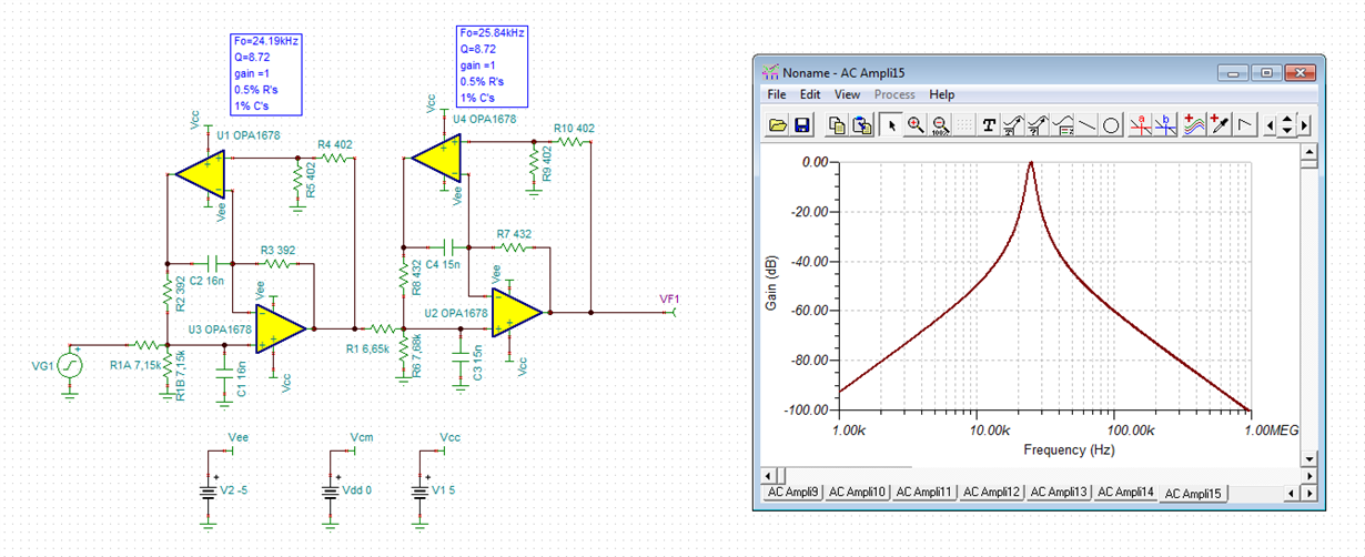
  • And, Tom pointed me to the perfect part for this - the OPA1678 dual audio amp, updated at bottom of word file with its TINA file

    25kHz 4th order BP suggestions updated AM filter.docx

    AcerbergMossbert BP with OPA1678 25kHz redesign 4th order.TSC

  • Hi sir,

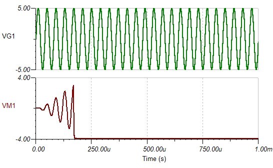
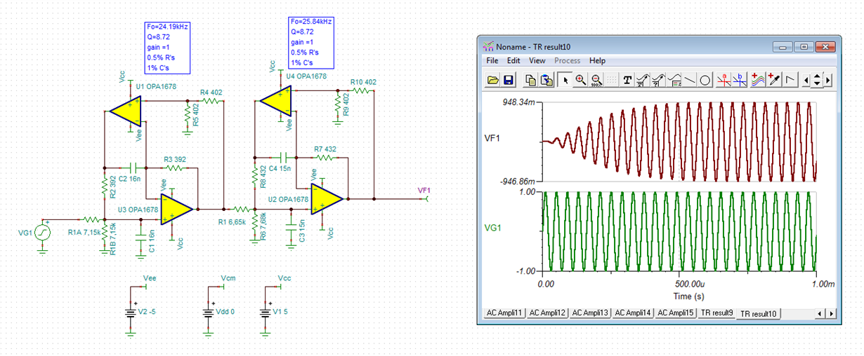
    I run your design(OPA1678) in TINA-TI, AC transfer is okay, but transient result have some problem as attached file. 

    Can you help to check it?

  • Hi Michael,

    AcerbergMossbert BP with RC4558 25kHz redesign 4th order.TSC can be download, but can't open by TINA. Can you send it again? Thanks!
  • I also have a lot of problems running transient, get kind of random results depending on time length, not sure - the V7 version of the RC4558 is attached 4213.AcerbergMossbert BP with RC4558 25kHz redesign 4th order.TSC

  • Morning all,

    Well, as I said at one point I normally only get LP filter questions and virtually no BP questions - so it was time to explore this DABP approach.Wow, how cool and simple is this? It can't generate more than a 2V/V peak gain, but otherwise seems pretty simple and powerful. One thing to keep in mind is these designs generate exact RC at first, and then you need to step them off to E96 R's and E24 C's - that always give a shift in the nominal response from your design goal - then you apply tolerances on those for spread.

    Here I assembled the targets 2 stages for your design Tsing and looked at it in detail - OPA1678 implementation attached as well - So only 2 duals now and looks as good as the Akerberg Mossberg - that one can generate easily tuned wide range of peak gains though.

    4th order BP using the DABP topology.docx

    4th order DABP with OPA1678.TSC

  • Hi Michael,

    here are my results of your last simulation. (I replaced the current source by a voltage source, for clarity, and added a measuring point to the output):

    tseng1.TSC

    Kai

  • Yes Kai, these are what I see also - I probably attached the last sim I did testing the input impedance, these look pretty good don't they?
  • Hello Tseng,

    I hope the collective responses from Kai, Michael and myself provide sufficient information for you to apply the DAPB filter effectively in your application. If so, please go ahead and close this e2e inquiry.

    Regards, Thomas

    Precision Amplifiers Applications Engineering

  • Hi all,

    I really appreciate all the hard work you've done to help me.

  • Hi Michael,

    yes, looks good. Unfortunately, I cannot carry out a phase stability analysis.

    Kai
  • Right Kai, an alternate that usually works is to sweep output spot noise to very high F - if the phase margin is low, you will see a spike near xover. I did not see anything. 

  • ...the wise words of a true master...

    I already knew the trick of looking at the voltage noise density plot of an OPAmp to find any hidden internal chopping. But to see instability from the simulated output spot noise was new to me. Thanks!

    Kai

  • thanks Kai, we often have low phase margin with new FDA's in MFB circuits and I do a guick swept spot noise to see if I should go on to set up and run LG phase margin test - this will be in the next Planet Analog article in May.

    and actually that Chopper noise issue is something Jerry Steele has published lately in the context of that chopper noise being aliased by a convert clock - a hidden artifact in the physical channel. Not sure if that is modelled.

    www.planetanalog.com/author.asp