This thread has been locked.

If you have a related question, please click the "Ask a related question" button in the top right corner. The newly created question will be automatically linked to this question.

LM358B: How to measure open loop output resistance of an OpAmp?

Part Number: LM358B
Other Parts Discussed in Thread: LM358, LM324

Hi,

How is it possible to measure open loop output resistance of any particular opamp? Is there any worthwhile, reliable circuitry that allows to do such measurements?

Open loop Zo is't common in datasheets, however it is noted for some opamps. For example, LM358B does have typical value of 300 ohms (at zero output current) - how was it measured, which circuitry was used for that?

Thanks

  • Hey Oleg, 

    Welcome to e2e! 

    Would you like to measure the open loop impedance in laboratory setting on in simulation? Please check out this document and tell me if it resolves your question: 

    This specification is usually found in our datasheets in either the Electrical Characteristics table or in the plots. 
    This could also be a specification that is characterized by the design, therefore running a simulation will give you the result rather than testing it. 

    All the best,
    Carolina 

  • Hey Caro,

    Thanks for the fast reply!

    I'd like to measure the open loop impedance in laboratory. Since it is mainly the output resistance of an output stage, it's value can be very different at different output dc currents. From my latest experience, simulation models aren't accurate enough in modeling output resistance... Therefore I believe, it is more secure to measure it on a breadboard.

  • Oleg,

    Is there an end goal design planned or is this an educational endeavour? Do you have a way to measure phase and gain versus frequency? The gain phase data at two different loads can be used along with math to calculate Zout.

    The LM358B will have much lower out Z if the output current keeps the Darlington NPN or emitter follower PNP active and not switch between.

  • So Oleg, 

    I usually make these measurements with a HP4195 using its S11 measurement (it includes a lumped element modeling feature)

    Of course, to get open loop you need to run open loop but hold the output at some desired voltage or current as you mention. The actual open loop output impedance does change with voltage and current conditions and you could control that in test if desired. that is rarely modelled unless you do the model as transistor level instead of macro. 

    You would need to wrap a low speed integrator loop around the device to control the output voltage when testing to put it where you want it. 

  • Ron,

    Both. I develop a new project where LM358/LM358B will have a moderate capacitive loading on it's output, so it's necessary to guarantee it's stable operation. Sure, it's possible to do this job experimentally. However, I prefer to calculate it's behavior to be absolutely sure. Therefore I need to know it's output impedance.

    Yes, I can measure gain and phase. The issue is that we have to measure them when ac-feedback loop is open. But at the same time we must retain some feedback at dc to stabilize an operation point. I believe, this issue can be solved, but I wouldn't like to reinvent the wheel. Maybe there is some "typical" test circuit that is used by TI for such measurements?

  • Michael,

    Yep, output resistance is nonlinear, so it's necessary to measure it at "small signal" conditions. This is also an issue, since opamp itself has a plenty of gain and amplifies it's own noise. In result, small output signal can be lost in noise... Probably, some narrow bandwidth filter is needed...

    Michael Steffes said:
    You would need to wrap a low speed integrator loop

    Good idea, thanks!

  • So Oleg, I took this a bit further, This very old part is supplied from several places - for some reason I had a 2018 file using the ON Semi model which is transistor level - here that is set up for Zol sim

    LM358 ON model Zol test.TSC

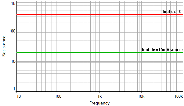
    Then I ran the sim, with no output current pretty flat at 851ohms, seems high, but 


    Then I pulled 10mA out of the output, yes that Zol changes a lot as it should using transistor modeling, down to 26ohms - surprisingly flat across F - makes me think their transistor models are too simple,

  • Oleg,

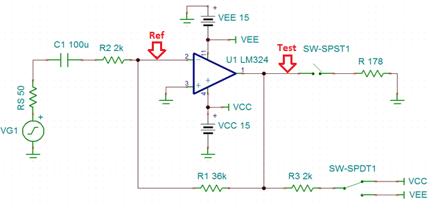
    In the past, I used this circuit to get Zo for sourcing and sinking current on LM324. Gain was measured TEST/REF across frequency and the gain difference was recorded with SW-SPST1 open and closed along with the value of the resistor to calculate the effective Zo 

    The attached spreadsheet omits complex numbers (uses only gain difference, doesn't use phase) but this is fine for LM324 (or LM358)

    LM324 Out Z simple test.xlsx

  • Michael, thanks for these simulations. Previously I did some simulations too, and the most believable model was LM358N by National. Although it shows only active resistance independable from frequency, it's values look plausible: ~350 ohms at zero output current and ~20 ohms at 10mA (source). Simulation circuit was identical to yours, except for a resistor in place of inductance. Anyway, I will try to do measurements in the lab using integrator for DC biasing.

  • if you used a resistor for feedback, were you not running closed loop? 

    Yea these flat R over frequency seem odd for actual transistor models. 

  • Ron, thanks for the calculations sheet.

    "...dB loss was nearly constant from 3KHz to almost 1MHz" - maybe this is the key. It may be possible to measure Zo in closed loop configuration if the signal frequency is high enough, so that opamp gain is significantly reduced...

  • Michael Steffes said:
    if you used a resistor for feedback, were you not running closed loop? 

    No, I used R=1GOhm and C=1GF feedback.

  • My test was closed loop , however, I looked at Vtest/Vref which is the open loop gain, forward gain.

    The final application will be a closed loop too. 

  • Ron Michallick said:
    I looked at Vtest/Vref which is the open loop gain

    I just noticed that the Ref point is at the inverting input, so you are right. Interesting idea.