Hi,
Pls find the below AMC1200 schematic of our DC Link voltage measure application. Here, after inverter turn on, the AMC1200 differential input (VINP-VINN) will oscillating to maximum voltage & output also changed to maximum. Due to this our inverter is going DC link over voltage & Brake chopper firing. find the attached wave forms for reference.
1) C1 & C2 DC Link Voltage, C3 is AMC out put & C4 is AMC input differential voltage.
Q1. What is the issue in below waveform, Any changes is required in circuit, pls let me know.
2) below waveform is circuit modified to -VDC side resistors shifted to +VDC side (8 resistor in Series) & GND1 (AMC1200) connected to -VDC. Here AMC1200 input oscillation is reduced.
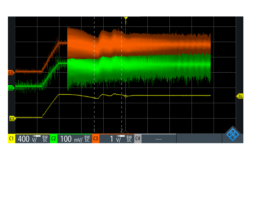
C1 is DC Link Voltage, C3 is AMC out put & C2 is AMC input differential voltage.
Q2. After connecting the GND1 pin -VDC oscillation is reduced. Let me know GND1 pin should be connected to -VDC or not.
Q3. same circuit can be used AC voltage measurement or not.
Thanks & Regards
Shiva Kumar T N