This thread has been locked.

If you have a related question, please click the "Ask a related question" button in the top right corner. The newly created question will be automatically linked to this question.

XTR106: Iret pins tied together if Loop - pins are isolated?

Part Number: XTR106
Other Parts Discussed in Thread: XTR116

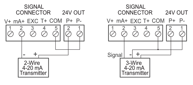
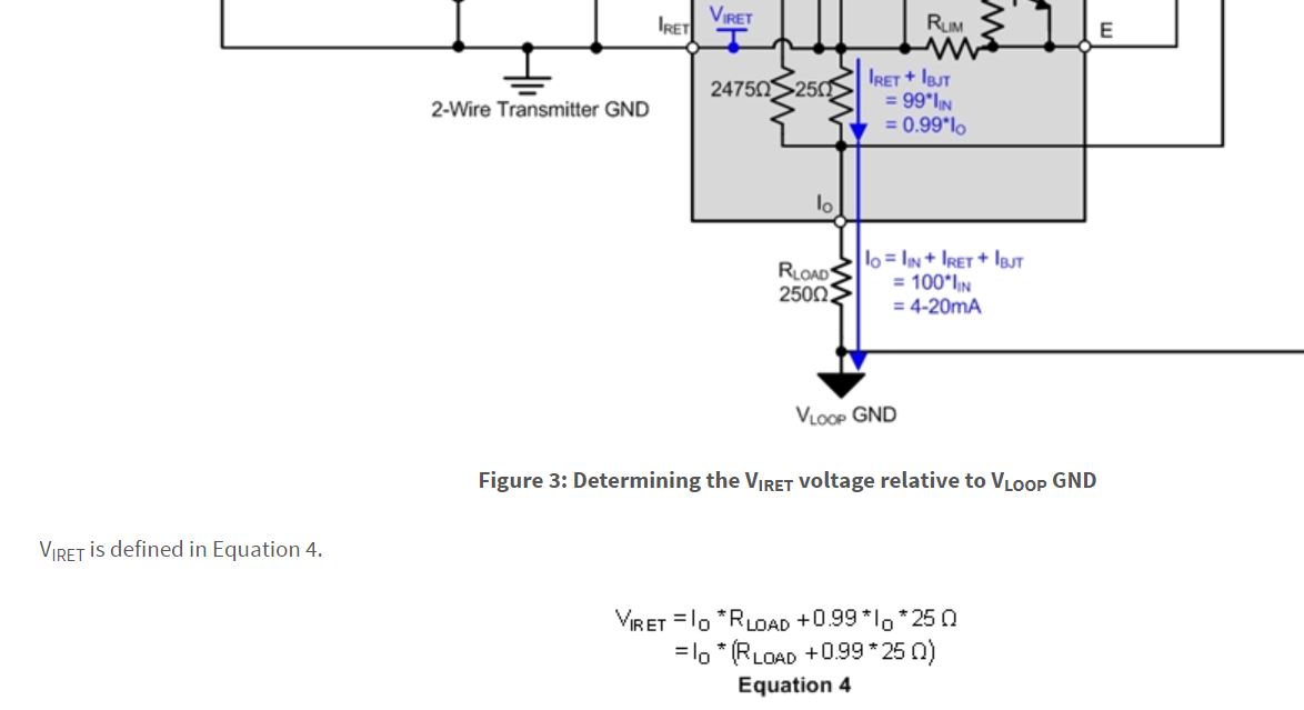
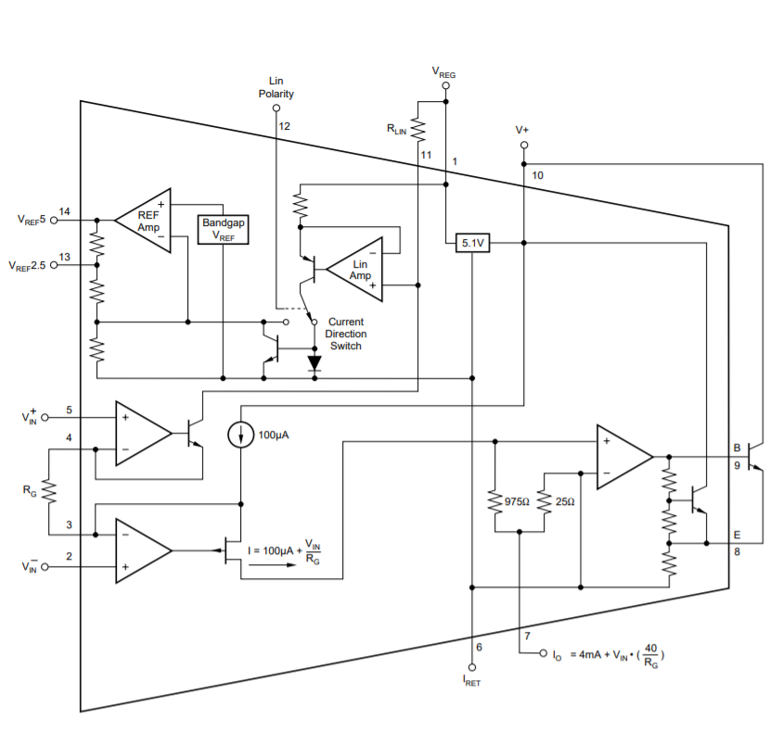
I have a case where I have two full bridge sensors, and the EXC- legs are tied together. The voltage outputs of the 4-20mA readouts are commonly isolated for UL safety reasons, so the negative terminals are floating with respect to each other, and to earth ground. In this case, is it possible to tie the Iret pins of the two XTR106s together? From reading this blog post, it does seem like it will be okay if Vloop- is not assumed to be ground. 

Thanks,

Paul

  • Hi Paul,

    so the two XTR106 are never connected to the same 24V loop voltage?

    Kai

  • Correct. If you consider a digital readout such as this one, the loop supply is isolated from the input due to product safety requirements. The LOOP + and LOOP - terminals of both XTR106 devices are isolated, and the Vref5.1 pins would not be connected, Only Iret.

    *Edit because the link does not work properly.*

    Under this product page, you can scroll down to  "Isolated Transmitter Power Supplies" and see the wiring diagram for isolated signal+loop power. I am also copying their figure here for clarity. 


    Source: https://www.predig.com/pd765#product-overview

  • Hi Paul,

    Unless I'm understanding what you're trying to do incorrectly, you cannot tie the Irets together. The voltages at each Iret pin need to float independently from each other, not just independently from the loop. From the blog series you shared, the equation for the voltage at Iret is given as:

    The voltage at Iret will be dependent on the current output, so this will not work if your two bridges are trying to output different currents. 

  • Hi Katlynne,

    Thanks for weighing in! I believe that Equation 4 assumes that VloopGND is 0V, and that is what I am saying is NOT the case. I'm not sure I will get the equations correct on the fly, but I think the equation would be rewritten like this:

    Vret = 0 (we have moved our reference point). VloopGND turns into Vloop- instead.

    Vloop- = -1 * ( Iret + Iin +Ibjt) * Rload + (Iret + Ibjt) * 25 (consider that voltage is negative because of current direction convention)

    For the digital readout I posted, they say Rload will be in the range of 50-100 ohms. Worst case voltage on Vloop- will be 20mA*100 = 2V. The outputs have a minimum of 500V isolation, but since the two readouts are independent, the isolation will actually be the 4kV from output to the AC input ground.

    Does this make sense?

    Paul

  • Hi Paul,

    Can you draw a schematic with what you are proposing. Using this block diagram of the XTR116 as an example (no load connected), the voltage across R1 is seen at the non inverting input of the op amp, and the voltage across R2 is seen at the inverting input. The negative feedback keeps these equal. The voltages across R1 and R2 are both referred to Io. If you are holding Iret at constant voltage, even if Io becomes more negative to try and compensate, you're also increasing the voltage across R1. This is why I believe it won't work.

    I don't fully understand the setup from your explanation. So if you could draw out how the two transmitters are connected together and to their individual inputs, supplies, and loads then we could take a look at how these potentials will float and give you a better answer on if it'll work or not. 

  • Hi Katlynne,

    I tried writing some equations, but when I went back and read your analysis again, it really helped that it was just first-principles of opamps! I agree, the negative feedback will try to drive the voltage difference between the inverting and non-inverting pins to zero. Taking this a step further, if the Iret pin is our reference voltage, then the Iin pin must also be at that reference voltage! This works for the XTR116 schematic above because Rin and Ros will allow those nodes on the opposite sides to be non-zero, and any current that needs to flow into the pin will. IF the CM Range of amplifier A1 is assumed to include 0V, this is a fine operating point. (I looked in the datasheet, but couldn't figure out if there was a way to figure out CM Range.) But, if the VSS of A1 is actually connected to the Io pin, then the requirement for CM range including ground even drops away, because we've already shown that the Io pin becomes negative compared to Iret.   

    I am more concerned about the behavior on XTR106, but I think the analysis holds. I can't see any reason why, if the arbitrary assignment of 0V to Io is broken, the device won't continue to operate correctly. It seems possible that the current source output of the built-in INA might not be happy, but that also seems unlikely. The key is that the Vsource supply is isolated, but again, that should be the standard for a digital readout these days due to the requirements imposed by UL or other safety agencies. I have attached one of two circuits on my PCB (sorry for not showing them both, but power-point schematics are quite tedious!) and the block diagram of the XTR106 from the datasheet.

    XTR106 block diagram

  • Hi Paul,

    in a perfect world without transients (ESD, Surge, Burst, etc.), EMI and with the ability of true isolation this would work. But, unfortunately, we aren't living in a perfect world :-)

    The problem is that transients coming from the one loop may travel to the other loop by running through both XTR106 now, concretely spoken through the pins 6 and the pins 7 across the internal 25R resistors.

    If I had to fix an existing design, I would add protection diodes as shown below (please ignore the Schottky at the top, it's from another thread :-)):

    But I think it's better to avoid this sort of coupling of several XTR106 right from the start.

    Kai

  • Hi Paul,

    I understand now and I think your assumptions and analysis are correct, so this should work ok. The only concern now will be the point that Kai brought up about transients flowing between the loops through the XTR106s. His proposed solution will be helpful. 

  • Great! Thanks to both of you for your help. Fortunately, I can guarantee that the twisted pair loops will run side-by-side to the readouts, which will also be side-by-side in a rack, but I will also include the silicon and schottky diodes that Kai recommands to be extra safe.

  • Good luck :-)

    Kai