This thread has been locked.

If you have a related question, please click the "Ask a related question" button in the top right corner. The newly created question will be automatically linked to this question.

TLV2471: Output voltage is not equal to expected

Genius 9880 points
Part Number: TLV2471

Hi Team,

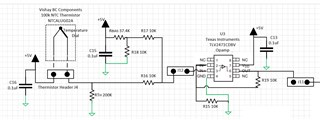
Customer is getting the expected output when TLV2471 used in summing circuit. Below is the details.

"

 I have re-tested the device configuration and am getting a good response based on "measured" inputs. The inputs (V1 & V2) i have created change values as soon as i power the circuit with them connected to the summing inputs. In isolation, V1 & V2 are correct according to voltage division rules but incorrect when powered.

For example:
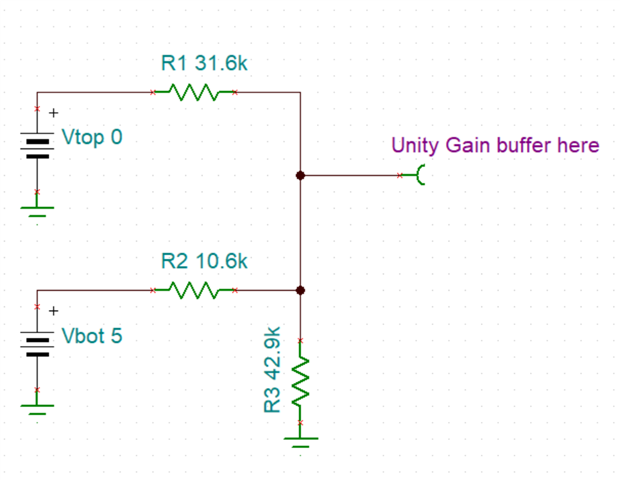
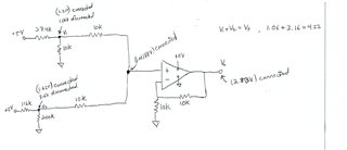
V1 is composed of a 10K and 37.4k resistor connected to a 5V source. Powered in isolation it provides an output of: (10/(10+37.4))*5= 1.06V
Note: when powered on, this same measurement changes to 1.21V

V2 is comprised of a 200k resistor and a 116K resistor connected to a 5V source. Powered in isolation it provides an output of: (200/(200+116))*5=3.16V
Note: when powered on, this same measurement changes to 1.62V

The powered on value when measured at the summing point is: 1.4188V
The output measures 2.83V (expected response given powered on values)

I was expecting to see 1.06+3.16=4.22V but did not see this?

"

Thank you in advance.

Regards,

Maynard

  • Maynard,

    The two inputs fight each other because they are connected together. The the op amp amplifies the end result. Later today, I'll suggest a summer that will give 4.22V

  • This resistor divider gives 4.22V output when both inputs are 5V. It gives 1.06V when top input is 5V and bottom is 0V. It give 3.16V when bottom input is 5V and top is 0V. The resistor values can be changed if the ratios are preserved. 

  • HI Ron, 

    Thank you for your support, customer have following inquiry for this. Below is the details.

    "Thank-you for the feedback. In my application, the top resistor divider will remains fixed at 1.06 V, however the bottom restive value (and voltage) will vary. The lower one changes as it is a NTC thermistor which changes its resistive values with temperature. The purpose of the top resistive value is to DC shift the NTC thermistor value by 1.06VDC which is needed for this application.

    My hope was to add 1.06V to the NTC thermistor voltage, thereby shifting it upwards. The full range of the summed inputs (NTC+1.06) will remains less than 5V.

    I am attaching the actual schematic that i have built today. As Ron can see, the NTC thermistor resistance (and voltage) will vary with temperature. The upper resistance (and voltage) are fixed, providing a DC bias which is applied through the TLV2471I opamp and summing circuit logic.

    If the TI team can offer a better solution for this or modification, it would be greatly appreciated."

    Regards,

    Maynard

  • Maynard,

    All I need is a linear equation or even easier, two points that make a line. Ideally the end points (at min and max temperature expected)

    Point1 (VOUT1, [thermistor resistance]1) and point2 (VOUT2 [thermistor resistance]2)

  • HI Ron,

    Apologies for the late response. Below is the new information provided.

    "The application is an electric water heater controller. The TI engineer is asking for a response plot for the two devices – a potentiometer that is used to set the water temperature and a NTC thermistor to measure the water temperature.  My goal is to try and overlay these response curves so I can then use a comparator to decide when the target temperature hits the measured temperature and turn the A/C heater relays on or off. 

    The engineer can play around with the two voltage division Rcal resistor values (one for the NTC and the other for the POT) if he feels it is helpful to develop a better curve match.
    "

    Regards,

    Maynard

  • Maynard,

    This still simplifies to 3 resistors. NTC and two fixed resistors.

    N = NTC resistor. S=supply voltage Vout = V = (S * B) / (B + A||N)

    Where A||N = (A*N) / (A+N)

    A simulator or excel formula can be used to tune this to the desired gain and DC offset.

    If they really really want two knobs to truly add them instead of mix them, then they will need to switch to an inverting amplifier setup. The NTC could be moved to ground side to re-invert the transfer function if desired. 

  • Hi Ron,

    Apologies, I missed attaching the plot. 

    TI response plot.xlsx

    Thank you in advance. 

    Regards,

    Maynard

  • Maynard,

    If the goal is to compare temperature to a pot, then do that in one easy step. TI response plot2.xlsx

    Use a comparator with hysteresis or add it externally

  • Updated circuit. added jumper, moved 0% to top 

  • Hi Ron,

    According to customer,  this solution work for them and they would like to thank you for your support.

    Regards,

    Maynard