This thread has been locked.

If you have a related question, please click the "Ask a related question" button in the top right corner. The newly created question will be automatically linked to this question.

OP_AMP Multiple Gain Stage Stability Analysis

Other Parts Discussed in Thread: OPA1671, OPA388

Dear Team,

I am designing a circuit that will convert 500uV signal to 1.5V.

I am using two gain stages in this design.

May I know how to check the stability of this circuit. Please find the attached TINA_TI file.

My I/P is coming from a MEMS microphone after blocking the dc content.Please let me know my method is correct.

Always open to suggestions to improve the circuit.

Multiple_gain_stage.TSC

Regards

Hari

  • Former Member
    0 Former Member

    Hello Hari,

    For multiple stage amplifiers, you'll want to test each amplifier one at a time.  We typically use two different methods for stability analysis depending on whether the feedback is a single loop or dual loop.  In this case, both amplifier stages are single loop.  So the process is relatively straightforward.  Just make sure you're amplifiers are properly biased so they do not rail.  You can do this by running a DC simulation.  I've gone ahead and done this for the circuit you sent me and it looks good.

    We've put together a presentation on how to do this.  Below is a slide from the presentation.

    Regards,

    Daniel

  • Hi Hari,

    has this thread to do with this one?

    Kai

  • Hii Kai,

    Yes :).

    Actually first I thought I will do that(Thread) with multiple gain stages.

    So I asked about it's stability.

    For mutiple gain stage frequency response do we need to check each ones separately.

    Regards

    Hari

  • Former Member
    0 Former Member in reply to Hari T O0

    Hari,

    Yes.  You will need to check the stability performance of each individual stage.

    Please let us know if you have any further questions.

    Regards,

    Daniel

  • Hi Daniel,

    I need to check the stability of AC cuopled Amp. Is the procedure same.

    Please find my circuit.

    7762.G-50_60.TSC

    Regards

    hari

  • Hi Hari,

    it's explained in the training videos in fullest possible details.

    Kai

  • Hi Kai,

    I tried to do with the help of videos.But I failed.

    Please find the attached PDF and circuit file which I used to test the stability.

    If you can tell me where I went wrong it will be helpful for me.

    Regards

    Hari

    PM_CALCULATION_CKT.TSCDoubt.pdf

  • Former Member
    0 Former Member in reply to Hari T O0

    Hari,

    Attached are the circuits for measuring stability.  Shown in the images below are the stability analyses for the first and second stages.  Looks like about 90 degrees of phase margin for both.

    Stage 1 Phase Margin

    Stage 2 Phase Margin

    Multiple_gain_stage_stability1_V9.TSC

    Multiple_gain_stage_stability2_V9.TSC

    Regards,

    Daniel

  • Former Member
    0 Former Member in reply to Former Member

    Hi Hari,

    Let me add that the circuit you show in your PDF will not properly measure phase margin because you are not measuring the product of the open loop gain of the amplifier and the feedback factor. The circuit in the PDF will give you a closed-loop response.  You need to open the loop in the AC.

    If you follow the method shown in our presentation, you will be able to take the proper measurements.  It will be explained in there.

    Regards,

    Daniel

  • Former Member
    0 Former Member in reply to Former Member

    Hi Hari,

    Let me add that the circuit shown in the PDF does not work because you are not creating an AC open circuit in your loop, in addition to a couple other reasons.  You need to find the product of the feedback factor and the open loop gain of the amplifier.  If you follow the method shown in the presentation, it will guide you as to how this can be done.

    Regards,

    Daniel

  • Hi Daniel,

    Thank you for your support.

    I used indirect phase margin measurement (TI Precision Labs - Op Amps: Stability 4) given in the Page No 5 of below PDF and I obtained some different values.

    May i know where I went wrong

    https://training.ti.com/system/files/docs/1334%20Stability%204%20-%20slides.pdf

    Regards

    Hari

  • Former Member
    0 Former Member in reply to Hari T O0

    Hello Hari,

    I see.  I misunderstood and thought you were trying to run the more direct measurement in the AC.

    Which circuit would you like me to look at?  It seems as though you've changed amplifiers from OPA388 in the first circuit you linked to OPA1671.  Let me point out a couple of things I've already noticed:

    1. Make sure the amplifier is properly biased.  You have a single supply and and your input starts at 0V.  So, the amplifier may not be in its proper linear operating region.  These parts are rail-to-rail, but I'd still leave a little margin to the rail.

    2. You need your output to change by 10mV to 20mV.  Clearly, this is not occurring for you.  Please let me know which amplifier you're using and I can take a look at it in more detail.

    Regards,

    Daniel

  • Hi Daniel,

    Please find the attached circuit. I will be going with OPA1671.

    The attached PdF file contains my calculations, circuit diagram and O/P waveform.

    Please let me know where I went wrong .

    Doubt-1.pdf

    PM_CALCULATION_CKT - autosave 20-01-29 09_53.TSC

    Regards

    HariPM_CALCULATION_CKT - autosave 20-01-29 09_53.TSC

  • Former Member
    0 Former Member in reply to Hari T O0

    Hello Hari,

    Looks like the mistake is a fairly simple one: the op amp was not properly biased.

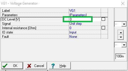
    Note that the supplies for the amplifier are 0 and 3V, yet the DC voltage of the unit step voltage source is 0V.  So the input voltage is just ramping from 0 to 241uV.  This is too close to the rail and, if you just move the input signal a bit off the rail, you'll see the expected answer.

    To make the output easier to understand, I changed to supplies to +/-1.5V instead of changing the input voltage.  You can see the circuit I used below and how we now get a 12mV output step.  The lack of overshoot points to a high phase margin.

    Please let me know if you have any further questions.

    Regards,

    Daniel

  • Hi Daniel,

    Thank you very much.

    "if you just move the input signal a bit off the rail, you'll see the expected answer." This statement means I need to add some DC level to the input signal.

    Please correct me if I am wrong.

    May I know how to decide the required Dc level.

    What are the things to be taken care of when doing stability analysis of single supply opamp circuits?

    Regards

    hari

  • Hi Hari,

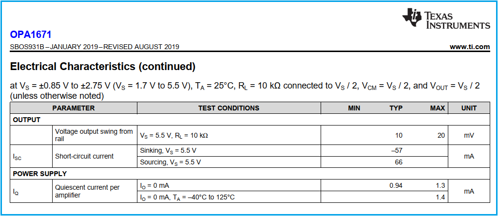
    the output voltage of OPA1671 cannot fully reach the supply voltages ("rails") 0V and 3V in your circuit. Or, by other words, the output voltage swing is limited, as mentioned in the datasheet:

    Kai

  • Former Member
    0 Former Member in reply to kai klaas69

    Hi Hari,

    Kai is correct.  Consider the "Common-Mode Voltage Range" for the input voltage and the "Voltage output swing from rail."  From the datasheet for the OPA1671, the common-mode input can swing from supply rail to supply rail.  However, the output needs 10 to 20mV of headroom.

    Considering the gain across your amplifier, you'll need to ensure the input voltage is high enough so that the output voltage will stay within its operating region.  You can do this by moving the DC input level as you've shown.

    If you're getting really bizarre results during stability testing, such as really high or low amplitudes in the AC, then it's a good idea to check the operating region of the amplifier.  Oftentimes, this type of result means the amplifier's output is stuck at one of the supply rails.

    Regards,

    Daniel

  • Hi Daniel and Kay,

    Thank you very much.

    I am clear with common mode I/P range.

    But the statement "However, the output needs 10 to 20mV of headroom.",does it mean O/P cam go maximum 10mv below rail,here it is 3.3V.

    Could you please expelling the term "Voltage O/P Swing from rail" with an example so that I can easily understand.

    Regards

    Hari

  • Former Member
    0 Former Member in reply to Hari T O0

    Hello Hari,

    It means that the output will need to be at least 10mV (typical) to 20mV (maximum) above the lower supply rail and below the positive supply rail.  So for this case, we would do from +20mV to +3.280V.

    The op amp cannot output a voltage that is beyond the supply rails, only within the rails.  The "Voltage output swing from rail" specification tells you how close to the rails you can get.

    Regards,

    Daniel

  • Hi Daniel,

    Thank you very much.

    I understood that concept of "Voltage output swing from rail" .

    Will study more about single supply opamps and their stability this weekend,will contact you if I stuck any where.

    Thanks & Regards

    Hari

  • Former Member
    0 Former Member in reply to Hari T O0

    Hi Hari,

    Hope this was helpful.

    Please let me know if you have any further questions.

    Here are some resources on the subject.  Note that some information, such as part suggestions, will be dated:

    http://www.ti.com/lit/an/slyt189/slyt189.pdf

    http://www.ti.com/lit/an/sboa059/sboa059.pdf

    Regards,

    Daniel