This thread has been locked.

If you have a related question, please click the "Ask a related question" button in the top right corner. The newly created question will be automatically linked to this question.

TLC555: Sequential Timer Circuit Issue

Part Number: TLC555

Tool/software:

Hi team,

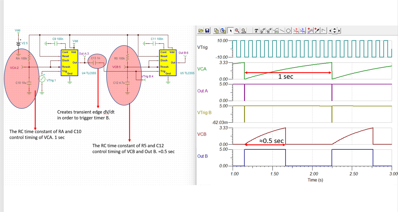
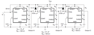
My customer wants to build a serial time delay structure. And totally based on the example schematic of our datasheet, but only with the first two TLC555.

They found that:

1. The first TLC555 sends a pulse, and a 1nF capacitor needs to be added to the input port
2. The first TLC555 needs a certain time interval for the input of the TRIG signal to send a pulse. After testing, it is found that the first tlc555 thres has been discharged, and the input capacitor has also been discharged. What parameters determine this time interval and how to calculate it?
3. For the TLC555 to output a pulse normally, it must be a signal pulse from low to high. The input signal cannot be low or high all the time.

Could you please help to answer these questions?

Thanks!

  • Hi Matt, 

    I have built the circuit in Tina Ti and it operates as expected. The tina simulation is attached at the bottom of this post. I have put together a slide below showing how the timing works with the RC time constants. I do recommend TVS diodes on the trigger pins of timer B and consecutive timer trigger lines due to the transient dV/dt created by the 1 nF capacitors. This will help protect the trigger line from getting pulled above the supply rail. The RC time constants can be adjusted by changing RC values. Is the customers circuit designed using these values?

    TLC555 Sequential.TSC

    Best Regards, 

    Chris Featherstone