Tool/software:
Setups:,
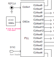
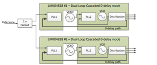
In case of two LMK04832, where one in single loop 0-delay mode (master) and another in distribution mode (slave) with CLKin1 used on both.
1. master get 100MHz REF IN while slave get A output clock from the master, for example CLKout8 at 156.25MHz
2. both master and slave get the same SYNC signal from the pin
Questions:
1. was it feasible to have both Device clock and SYSREF outputs aligned from both master and slave?
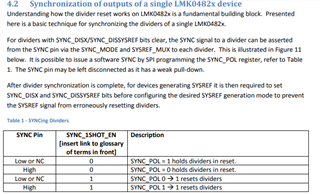
2. was there any registers settings in particular need to be done in this setup?
Thank you.
Hello,
Would it be possible for you to share a clock tree or schematic of the system you are trying to achieve? I need to make sure it is feasible.
Thanks,
Michael
Please see the SCH about PLL. the CLKIN0 is connected to an 100M OSC and OSCin from an onboard 100M VCXO.
It was reviewed in 2021 by TI.
We use CLKin1 and do not use CLKIN0 nor OSCin because we need distribution mode beside single loop.
About PLL SYNC pin, it's connected to either external or the FPGA via a OR gate.
When from FPGA, the SYNC signal can be from external source via another connector and re-timed inside FPGA.
PLL OSCout can be from FBMUX.
Actually, I got it work about half year ago with SYNC_POL and could not reproduce it now with same FPGA and PLL registers.
Thank you very much.
Hi Michael,
Any updates?
I did more tests regarding the SYSREF phase alignment.
1. The SYSREF has same fixed time delta to the CLKout8 (100MHz) after programming on the same board without SYNC SYSREF routine as 8.3.3.1.
2. The SYSREF phase from two boards are changed every time by programming.
3. I'll update this thread with test results by running SYNC SYSREF routine tomorrow.
Thank you very much.
Hello again,
I have been looking between this forum and the other one you created. As I understand it, you want to synchronize two LMK04832s, with one as the master and one as the puppet. Both will receive the same SYNC signal, so the outputs of both buffers should be phase aligned. This could work with toggling the SYNC_POL bit, as well.
It makes sense to me that the SYSREF phase is changed every time by programming. These will only be phase aligned with the clock outputs upon a SYNC event.
The register sequence that should trigger that result internally is:
0x10200
0x14480
0x10A00
0x11200
0x11A00
0x12200
0x12A00
0x13200
0x14081
0x14400
0x13900
0x14319
0x14339
0x14319
0x10420
0x10C20
0x11420
0x11C20
0x12420
0x12C20
0x13420
Then, you should re-enable SYNC_DISSYSREF (0x14480) and set SYSREF_MUX back to 3 (0x13903)
It is a bit difficult for me to provide you with an appropriate configuration when I do not have your complete clock tree. Would you be able to provide me with a complete overview of the frequencies each board takes as an input and provides as an output?
Additionally, would you be able to provide me with a scope shot of your clock and SYSREF outputs (only need one of each) before and after a SYNC event?
Thanks,
Michael
Hi Michael,
#1
I did the same routine as above and also below, which is from TICS Pro v1.7.7.9.
The SYSREF outputs are still not aligned before and after toggling the PLL SYNC pin. I have a question about register 0x44, why was it set to 0x80 not 0xFF?
0x010200,
0x0144FE,
0x010200,
0x0144FE,
0x010A00,
0x0144FC,
0x010A00,
0x0144FC,
0x011200,
0x0144F8,
0x011200,
0x0144F8,
0x011a00,
0x0144F0,
0x011a00,
0x0144F0,
0x012200,
0x0144E0,
0x012200,
0x0144E0,
0x012A00,
0x0144C0,
0x012A00,
0x0144C0,
0x013200,
0x014480,
0x013200,
0x014480
#2
I have also tested with SYSREF as the feedback clock at 1.25MHz and 3.125MHz plus set SYSRED DDLY_PD to '1'. The phases are still not aligned.
Thank you very much.
#3
1. Please attached SYSREF from two boards.
2. The phase delta is the same before and after toggling the PLL SYNC.
3. The same PLL SYNC signal to both boards.
4. However, the phase delta differs on each time programming the PLL.
Thank you very much.
Hi New2day,
Michael is now OoO so I will assist you.
Please provide a high-level block diagram/clock tree with all frequencies of what you're trying to do here to better assist you.
I understand you need to synchronize two LMK04832s - one operating as a master and one of the outputs being fed to another LMK04832 in distribution mode and you need all outputs of both devices sync'd.
Normally to accomplish this you need a shared sync signal for both devices.
As a matter of fact, you won't be able to generate a SYSREF output on the first device without first performing a sync event.
Best regards,
Vicente
Hi Vicente,
1. Please see below the diagram, where one PLL per board.
2. The tcs file is attached too. Which indicate one of the configuration I'm currently testing.
The PLL will be in single loop 0-delay mode that will get the same 100MHz clock reference (phase aligned) to CLKin1.
There is no master or slave relationship.
Thank you very much.
Hi New2day,
There is no master or slave relationship.
You say this - so you simply require the second device to operate as a buffer.
You only care about the master device having its output sync'd - is that correct?
I see you have a 100MHz VCXO - I assume CPout1 is driving that correct?
I see you're setting the SYSREF divider as the feedback.
Can you try setting CLKOUT6 as the feedback?
This will make one of the 100MHz outputs will be fed back to a 100MHz PFD.
You can still use the outputs - the feedback happens internally.
In the configuration you provide you have all sync disable bits enabled.
So, in other words, you're preventing all OUTPUTS and the SYSREF divider from SYNC itself.
Try this new configuration I provided.
A sync event should now give you deterministic phase.
Are you using an EVM + TICSpro or your own board and custom controller?
Best regards,
Vicente
Hi Vicente,
#1
Like to make it clear - the PLL on each board will be set to single loop 0-delay mode.
The reason said the slave in distribution mode before (above) is could not get SYSREF outputs phase aligned and it's not desire mode.
#2
I'm using customer board with help from TICS Pro.
I've tried with both CLKout6 and CLKout8 as FB clock. Could not get SYSREF outputs aligned nor CLKout10/CLKout12.
Thus, I'm trying with using SYSREF as FB clock instead. However, still could not get SYSREF outputs aligned (0 phase delta).
The phase delta between SYSREF outputs are varied every time programming and no change by toggling the SYNC pin.
#3
The tcs file I've attached before is before the SYNC Dividers routine. Please see the SYNC Divider routines above and also following three register writes before the SYNC pin are toggling from LOW to HIGH then LOW simultaneously.
0x014093,
0x014400,
0x013900,
After SYNC pin back to LOW ('0'), following register writings will be happening as suggested from TICS Pro when click SYNC Dividers button.
Only difference is the register 0x144 (red below), it says 0x014480 from TICS Pro. However the SYSREF and clock outputs are not stable when 0x144 = 0x80 (this is my question too, see previous above).
0x010C20,
0x011420,
0x011C20,
0x012420,
0x012C20,
0x013420,
0x0144FF,
0x014311,
0x013903,
Thank you very much.
Hi New2day,
1. Understood - all you want is two LMK04832 operating in single loop ZDM mode with phase aligned outputs.
If you could share a clock tree that would be extremely helpful. From the schematic you showed I have no idea how these two boards are connected together or whether they share a reference you you require outputs on both to be deterministic in regards to the ref clk.
2.
I've tried with both CLKout6 and CLKout8 as FB clock. Could not get SYSREF outputs aligned nor CLKout10/CLKout12.
When you tried both of these - after performing a sync event would you have deterministic phase?
Many times your outputs will not be phase aligned due to external factors such as prop delay on board due to layout.
A sync event would be successful if every time you had deterministic phase - not necessarily aligned rising edges.
I utilized CLKOU8 as FB_MUX and was able to get deterministic phase every time between DCLKOUT & SYSREF.
Now they are not edge aligned but you can use the digital delays to account for this.
R324 (0x144) controls the following;
I get a stable continuous SYSREF output when i press "sync divider."
Can you give me a step by step procedure of what you're doing? I
Best regards,
Vicente
First of all, I like to get all clock and SYSREF outputs from two boards phase aligned, which means 0 phase delta, for example all SYSREF outputs.
1. our clock tree is very simple, LMK04832 is in single loop 0-delay with CLKin1 as reference clock input (CLKin0 and OSCin are not used)
2. two boards are identical so that the PCB traces and so on are identical for the inputs or the outputs of LMK04832
3. both boards get the same 100MHz reference clock to CLKin1 via the same length cables so phase aligned at CLKin1
4. the SYNC Dividers routine follows TICS Pro with toggling the PLL SYNC pin not 0x0143 bit[5], see below and also above.
0x010200,
0x0144FE,
0x010200,
0x0144FE,
0x010A00,
0x0144FC,
0x010A00,
0x0144FC,
0x011200,
0x0144F8,
0x011200,
0x0144F8,
0x011a00,
0x0144F0,
0x011a00,
0x0144F0,
0x012200,
0x0144E0,
0x012200,
0x0144E0,
0x012A00,
0x0144C0,
0x012A00,
0x0144C0,
0x013200,
0x014480,
0x013200,
0x014480,
0x014093,
0x014400,
0x013900,
toggling PLL SNYC pin (LOW-HIGH-LOW)
0x010C20,
0x011420,
0x011C20,
0x012420,
0x012C20,
0x013420,
0x0144FF,
0x014311,
0x013903,
5. did you test with one or two boards? With two boards, if leave 0x144 to be 0x80 after the SYNC routine, the SYSREF from two boards are not locked to each other afterwards.
Why did 0x144 need to be set to 0x80 but not 0xFF? Thank you.
Hey New2Day,
Vicente and Michael are currently out of office, but I will look into this and get back to you by tomorrow.
Regards,
Will
New2Day,
I am assuming that your clock tree looks something like this, but in single loop mode. Can you confirm?
In this case, once all PLLs are locked, all SYSREF clocks and all clocks which have a (greatest common divisor) GCD(SYSREF Frequency, Clock Frequency) = to the SYSREF Frequency, provided SYSREF frequency less than clock frequency, will have deterministic phase with one another.
If you want to share your desired output frequencies, we can confirm if this configuration will work. But assuming they are all you need to do to achieve synchronization is to sync the output dividers.
Let me know if you have any other specific questions.
Best,
Will