Tool/software:
Hello,
I am using the CLK104 board from Xilinx which contains LMK04828B and LMX2594 PLLs to drive clocks int the ZCU208 eval board from Xilinx again. The CLK104 board also has 3 input reference clock options: on board TCXO, SMA input, Recovered clock from FPGA.
I have same problem as in this thread https://e2e.ti.com/support/clock-timing-group/clock-and-timing/f/clock-timing-forum/1229913/lmk04828-taking-driving_clock-from-another-input-pin-and-i-can-t-figure-out-which-one/4661353#4661353
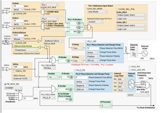
So, I wanted to use the external reference clock input for the LMK via the CLK104's SMA input and not use the CLK104's on board 10MHz TCXO. I used TICS pro app to only select CLKin0 as the PLL1 input and even if I don't supply any reference clock at SMA input, I still see LMK outputting 500MHz clocks at the outputs (DCLKout0 and 6 as programmed). However the Holdover mode is enabled for LMK (not sure if this has got something to do with)
Any help here is greatly appreciated. Thanks!
Hi Ponnanna,
Are you testing this with an evaluation module? If so, can you tell me whether the LEDs indicate lock for both PLLs? As I imagine it, the LED corresponding to PLL2 should be lit up, and the LED corresponding to PLL1 should not. This is behaving as expected. PLL2 is turned on because the output of the external VCXO (160 MHz) is phase synchronized with the frequency of the on board VCO (3000 MHz). It will generate an output even without an input. However, your intended use is to make the phase relationship between the input and output of the device deterministic - which can only be achieved if you drive the input with the specified 10 MHz signal.
If you do not want an output signal, set the corresponding clock outputs to powerdown mode.
Thanks,
Michael
Hello Michael,
Thanks for your answer.
Yes, I am using the evaluation module called CLK104 from Xilinx. Regarding the LEDs, I looked at the schematic for the CLK104. So, I see that only PLL2 Status pin (Pin 48: Status_LD2) from LMK chip is connected to an LED while PLL1 Status pin(Pin 31: Status_LD1) is used as an input instead of an output LED. So, when I load my custom register values from TICS pro I see Pll2 LED is "ON" and you say this is expected.
In other words, I cannot know if PLL1 lock status from LED observation. I was also looking at the LMK datasheet for a register address to contain PLL1 lock status. Unfortunately I did not find any. Could you tell me if there is a register that holds the PLL1 lock information?
Thanks
Best Regards
Ponnanna
Hi Michael,
Meanwhile I found that, PLL1 DLD status can be mapped to pin Status_LD2 as per LMK datasheet Register R351(0x16E) bit 7 : 3.
So, we tried this and PLL1 DLD is OFF initially without an external clock. The LED is ON after I provide the external 10MHz clock.