This thread has been locked.

If you have a related question, please click the "Ask a related question" button in the top right corner. The newly created question will be automatically linked to this question.

LMK04828: LMK04832/LMK04828 driving LMK04828 single ended reference input

Part Number: LMK04828
Other Parts Discussed in Thread: LMK04832, LMK04616, LMK00804BEVM, LMK1C1104, LMK00804B

In a recent post, I was seeking assistance in deciding between a few different devices (LMK04832, LMK04828, and LMK04616) to serve as a master device driving two (eventually 4)  slave LMK04828.  Derek with TI did an excellent job conveying the characteristics of each.   As that post was getting long, I wanted to create a separate post for discussing the output drive configuration of the master device. Simple block diagram below for context, followed by questions:

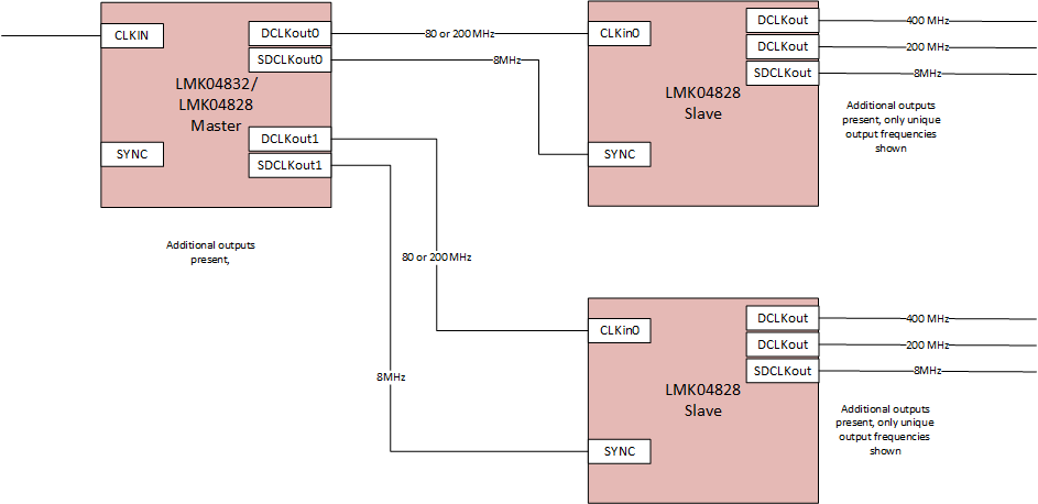
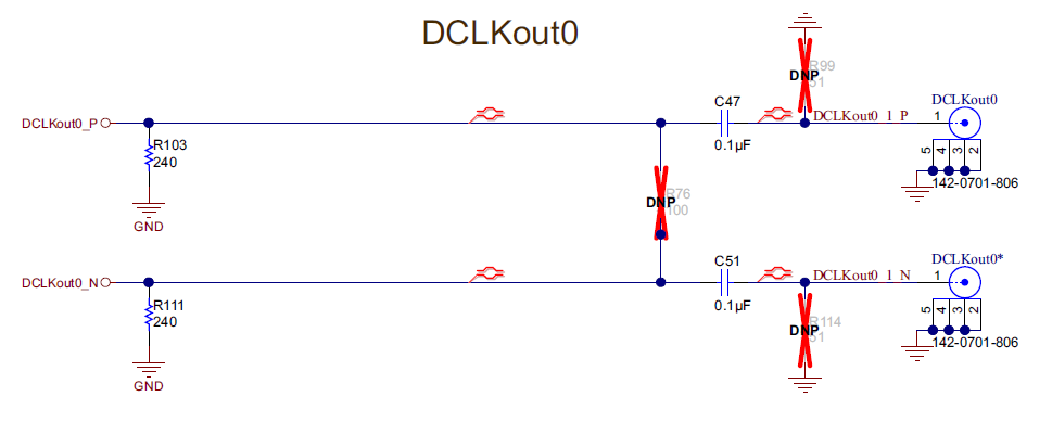
The master device, due to existing board constraints, must drive the slave devices through a single ended input to the slave board, AC coupled, that goes through 3dB attenuator before reaching the slave LMK04828 reference input.   This means that any differential drive not involving additional circuits or balun would need to be terminated on the master board.  The drive to the slave single ended input may be either 80MHz or 200MHz. Further, for our initial trials, the master board will be hosted on one of the existing TI dev boards.  Please consider these points when answering my questions:

1. For the case of the LMK04832 as master, which is indeed what seems like the best fit, I am planning to use the LVCMOS output configuration to drive the slave LMK04828, this should require minimal change to the dev board output terminations.  With the mentioned constraints, does this seem like the best choice?

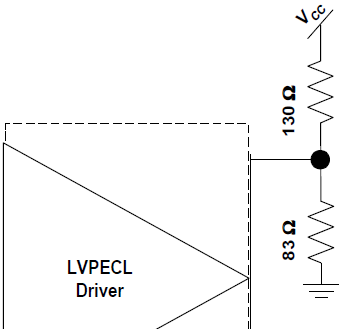
2. For the secondary case of using a 3rd LMK4828 as master, Derek reminded me that LVCMOS is only supported on OSCOUT.  Derek mentioned using LVPECL (in context of another conversation) on LMK04828 to drive the AC coupled single ended reference input of the slave LMK04828s.  I wanted to confirm with Derek or others if this would indeed be the optimal choice given the constraints we have as far as termination option.

Thanks

  • Hi usethewrench,

    First, your image didn't load properly, can you please reupload?

    Second: normally we break down E2E responses based on product owners, and I am responsible for dual-loop jitter cleaners. Are you asking for a second opinion? I can get a colleague to offer their responses as well, just let me know.

    As for your questions:

    1. LMK04832 with LVCMOS seems like the best option. One thing I forgot to mention: the LMK04832 has LVCMOS output format on odd-numbered outputs (1, 3, 5, 7, 9, 11, 13), outputs 8/10, and OSCout. Most even-numbered outputs (0, 2, 4, 6, 12) do not have LVCMOS output format.
    2. I'll break down three options, depending on effort and external component availability. Since you are working with an EVM for the master board:
      1. If you have a balun for 80-200MHz range, this is the preferred option for retaining the slew rate benefits of the differential signal. Of course this requires additional circuits, but nothing in the question suggests that this is disallowed. The datasheet indicates ADT2-1T+ baluns were used for some parts of the characterization of the LMK04828, so this might be a good starting point.
      2. If you cannot modify the layout and for some reason cannot use a balun, terminating the unused leg at the end of the differential pair is acceptable. In this case it is more valuable to prevent the unused leg of the trace from acting like an RF stub.
      3. If you can modify the layout (for example, if you are willing to cut the trace), and for some reason cannot use a balun, terminating directly at the master is best remaining choice for minimizing the stub trace and any potential reflections that would be created.

    Regards,

  • Hello Derek,

    Hopefully my re uploaded diagram works.

    I was hoping that you would be able to respond, I just didn't want to come across as demanding or dictating who should respond, if perhaps you and another of your colleagues shared the load.  I do not request opinions beyond yours.

    1.  Excellent (please see my question 3 for follow up question)

    2. a.  I like this option, and indeed it is preferred. My plan is to purchase baluns, not sure if I will have connectorized versions in time for first use (Ideally with characteristics/performance like the ADT2-1T+, but connectorized like the ADC-WB-BB).  Do you know of anything connectorized like the ADC-WB-BB, but having performance similar to ADT2-1T+ for frequency of 8MHz and 200MHz?   Also, thanks for pointing out the ADT2-1T+ being in used in characterization, great information to have in mind.

    2.  b and c: I believe i understand what you are proposing for b and c, but to confirm, can you indicate where and how in the schematic below you would terminate ?

    3. For the LMK04832, all of the clock skew specs have one of the notes below applied (14 or 15).  As LVCMOS is not mentioned, I am a little wary. For all LVCMOS outputs, should i expect the skew to be worse than specified for the differential modes?  For the LMK04832, perhaps driving single ended slave through balun, would the skew be significantly better using one of the differential drive modes (than current plan of using LVCMOS drive)?

    (14) Valid for CML 32 mA, CML 24 mA, CML 16 mA. CML DC bias is 50 ohms to Vcc or 68 nH to 20 Ω to Vcc.
    (15) Valid for HSDS 8 mA, HSDS 6 mA, LVDS. LVPECL20, LVPECL16, LCPECL with 120 Ω emitter resistor to ground.

    4. For LMK04832, have you found that you are able to attempt to compensate for skew between outputs somewhat effectively using delay adjustment? If so do the delay values used to compensate result in similar compensated skew results between powerups (ie, can one get semi repeatable results between powerups, assuming one lets device get to thermal steady state)?

    5.  I am considering trying a LMK00804BEVM between the master and slave for a few different cases. One case is 1 buffer for each output frequency (200MHz and the 8 MHz sysref), on the basis that it would mean all outputs of a given buffer had a max skew of 35ps, as opposed to the 60ps of the 4832 or 4828.  I understand the skew between the output of 1 buffer and any other buffer could then be worse, and there would be additive jitter, but for such a purpose, would that be your recommended buffer? Another case for use is to use buffers only for sysrefs, to save outputs, wherein I would likely use a slower 8 output buffer.

    Thanks

  • Hello usethewrench,

    Block diagram appears to be present now.

    2a. Not sure about any specific baluns for your frequency range, I know ADT2-1T+ goes down to 400kHz and up to 450MHz so it should work for your desired frequencies. If money is no obstacle, several vendors such as Minicircuits sell pre-mounted evaluation boards for the ADT2-1T+ and other comparable baluns. If you need more than one or two, it isn't very technically challenging to design small breakout boards for specific balun footprints, panelize them, and make a few dozen for less than the cost of one or two pre-mounted boards--purchasing hurdles notwithstanding.

    2b and 2c. Termination would be 50Ω on R99 or R114. You still need the emitter resistance and the AC-coupling capacitor. 2b would use the board layout as-is, while 2c would assume enough control over the layout to push the termination values physically very close to the IC. As an alternative with only two passive components on the unused leg, you could use a DC-termination to 130Ω/83Ω as in the image below. 130Ω || 83Ω = 50.66Ω, and if VCC = 3.3V, Vcm = 1.286V which is about equivalent to VCC - 2V. Again, the components for this termination style are not available on the LMK04828EVM layout, so you would need control over your own layout (or some clever rework with a hobby knife).

    3. I looked through our characterization data but I did not see anything for LVCMOS skew. I expect that the LMK04832 LVCMOS skew will be comparable to the typical skew specifications given for the other formats.

    4. Digital delay compensation will be exact across PVT to within the jitter specifications of the clock (i.e. < 100fs RMS), since digital delay is derived from VCO timing. However, digital delay compensation is coarse with a minimum step size of half the VCO frequency; practically it is limited to about 160ps per half-step. Analog delay variation is only available for SYSREF outputs on the LMK04832, but the delay variation is quite consistent over PVT. We might expect around 5-7ps variation in step size on a 21ps step for a typical part, most of which will be due to temperature. That said, analog delay absolute step width and variation over PVT is not characterized in the datasheet, so these are typical values only. The LMK04828 does have analog delay on both SYSREF and device clocks, but we found that the delay variation on the device clocks over PVT was actually greater than the step size in many cases, and because the analog delay block contributes to a higher noise floor by a few dB, we found that device clock analog delay was not of much value and ended up removing it in the LMK04832 in favor of the more tightly-controlled SYSREF adjustment. In both analog delays on the LMK04828 and the SYSREF analog delay on the LMK04832, the results are repeatable across powerups for the same voltage/temperature, but it can be challenging to control for all these conditions (especially across multiple devices, or in modular systems where one downstream device may be replaced by a new device with different process conditions/lot code).

    5. You might instead consider the LMK1C1104 (or the 2- or 3-output versions of the same IC), which has 25ps typical / 50ps max channel to channel skew, 400ps max part-to-part skew, lower additive jitter, lower power, and lower cost. Generally it makes the most sense to place device clocks and SYSREFs on separate devices, since the device clock to SYSREF alignment window is usually much wider than the allowable device clock to device clock skew. 

    Regards,

  • Hello Derek,

    2a. I will take another look at Minicircuits for the mentioned eval boards, thanks for the heads up.  With you in terms of a quick board being the way to go

    2b. Excellent, that was what I was expecting

    2c. Got it, thanks for the guidance, makes sense

    3. Thank you for checking the data, and for providing your expectation. With it, i will stick with the LVCMOS drive for now.

    4. This was particularly helpful

    5.  It is fitting you would mention the LMK1C1104, as it had come down to choice between it and the LMK00804B.  Overall, the LMK1C1104 is appealing, my concern was that I am planning to use it at up to 200MHz (one of configs to be evaluated), and I was concerned the performance might be degraded (as it has max of 250MHz relative to 350MHz of LMK00804B).   If operating the LMK1C1104 at 200MHz will not significantly degrade its apparent performance advantage over the LMK00804B, it does seem like a great choice,  may I please have your assessment on that matter?

    Thanks for your exceptional assistance

  • Hello usethewrench,

    I expect the LMK1C1104 performance at 200MHz will not degrade significantly, as long as you supply it with 3.3V. Any change in skew specs should be strongly correlated with frequency, so I would imagine that part-to-part frequency dependent variation will not increase much. Moreover, most of the electrical characteristics are validated with 156.25MHz; I don't expect more than 1-2dB reduction in amplitude at worst for a 1.3x increase in operating frequency.

    One correction: I looked over the datasheets again, and I believe the LMK00804B would actually be the lower power option (LMK00804B: about 20mA based on datasheet calculations; LMK1C1104: about 66mA, by doubling 100MHz test case). But the skew, additive jitter, and cost should still be in favor of LMK1C1104.

    Regards,