- How to create an ultrasound system from TI’s ultrasound portfolio?
The signal chain would be TX517 -> transducer -> AFE58XX -> TSW1400.
https://e2e.ti.com/support/applications/medical/f/30/t/401398
- To support SONAR applications, what are the modifications to be done in AFE5809 from the standard Ultrasound setup?
The LNA’s DC offset correction circuit consists of a HPF with a corner frequency set by CBYPASS that has to be changed to 1uF in order to prevent attenuation of the input signal for signals <100kHz.
http://e2e.ti.com/support/applications/medical/f/30/t/549672
http://www.ti.com/lit/ug/tidu702/tidu702.pdf
- Suggest Ultrasound transducers that can be used with TI Ultrasound devices.
Gemetal Medical Transducer from Sound Technology for US.
Vermon Transducer Company for Europe.
https://e2e.ti.com/support/applications/medical/f/30/t/479471
- Is the FPGA firmware / source code available for the TSW14xx boards?
The FPGA firmware source code for the TSW1400EVM can be accessed from the TSW1400EVM product folder at www.ti.com.
http://e2e.ti.com/support/applications/medical/f/30/t/306368
http://www.ti.com/tool/TSW1400EVM
- What are the recommended guidelines to use the ADS529xEVM, AFE58xxEVM with any FPGA board?
http://www.ti.com/tool/TIDA-00069
https://e2e.ti.com/support/applications/medical/f/30/t/433667
https://e2e.ti.com/support/applications/medical/f/30/t/408789
Here are some resources to assist with deserializing serial LVDS data on the receiver side.
http://www.ti.com/lit/an/sbaa205/sbaa205.pdf
https://www.altera.com/en_US/pdfs/literature/hb/stratix-iv/stx4_siv51008.pdf
- Please provide details about the Adapters from HSMC (Altera) and FMC (Xilinx) to interface to TI serial LVDS connectors
The following TI adapters can be used with our serial LVDS AFExx and ADSxxxx devices to interface with Altera and Xilinx FPGA boards.
http://www.ti.com/tool/HSMC-ADC-BRIDGE?keyMatch=hsmc-adc-bridge&tisearch=Search-EN-Everything
http://www.ti.com/tool/FMC-ADC-ADAPTER?keyMatch=fmc-adc-adapter&tisearch=Search-EN-Everything
- How to access the coefficient memory for the filter coefficient in AFE5809?
For Coefficient memory accesses, the SPI write is different than a standard SPI write of 24 bits. It will be a single SPI cycle access of 120 bits (8 bits of address followed by 112 bits of data with MSB first) The SEN signal should be low for the entire write time.
http://e2e.ti.com/support/applications/medical/f/30/t/566349
- How to load the saved settings at startup in AFE5809? Will the profile ram hold the configuration values after power off?
User-defined device settings cannot be used to configure the AFE5809 at startup but specific configuration steps can be saved in a CMD file by using the GUI’s “record command” and “save command” features.
http://e2e.ti.com/support/applications/medical/f/30/t/564931
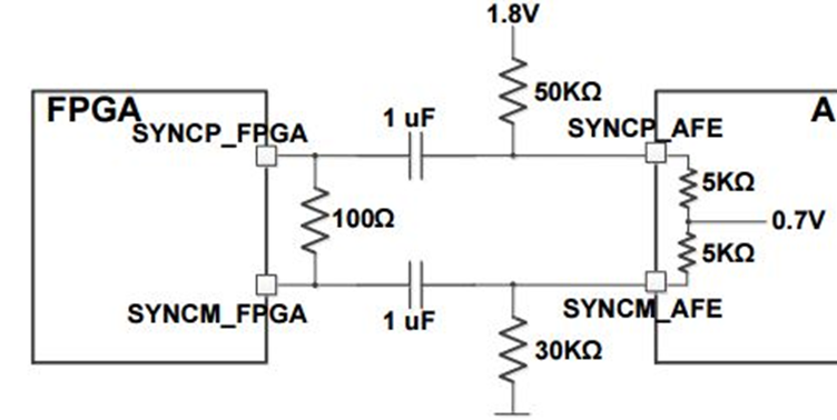
- How to terminate SYNC_SERDES, SYSREF_SERDES signals in ADS52J90?
SYNC and SYSREF pins’ termination were recently updated to the architecture below in order reduce glitches and false triggers.
https://e2e.ti.com/support/applications/medical/f/30/t/585265
- What should we do with unused JESD CML outputs pin, CLK_1X, CLK_16X input pins?
Unused JESD CML pins, CLK_1X, CLK_16X, NC pins can be left floating.
http://e2e.ti.com/support/applications/medical/f/30/t/550784
http://e2e.ti.com/support/applications/medical/f/30/t/547048
- Should we buy the interposer card to connect to AFE5801EVM to TSW1400 board?
The AFE5801 EVM ships with the adapter card for the TSW1400EVM. It does not need to be ordered separately.
https://e2e.ti.com/support/applications/medical/f/30/t/503459
https://e2e.ti.com/support/applications/medical/f/30/t/521907
- Provide details about the TX517 EVM power supplies and their functions.
The TX517 EVM requires all 11 power supplies and their functions are listed in the datasheet pin description section.
https://e2e.ti.com/support/applications/medical/f/30/t/535845
- True digital TGC devices (e.g. AFE58JD16) with accurate timing of when channel gains are changed vs SPI-controlled TGC devices.
Digital control of TGC via SPI intended for fixed attenuation/testing. Analog control TGC is piecewise linear but it is possible to specify the timing of uniform and non-uniform time gain control using programmed settings on our AFE5801, AFE5851, AFE5816, AFE58JD16 devices.
https://e2e.ti.com/support/applications/medical/f/30/t/531483
- Details about LVDS bit and Frame clock of ADS52xx and AFE58xx devices.
The LVDS bit clock and the frame clock scales down based on the decimation factor.
The LVDS bit clock frequency (LCLK) is dependent on the sample rate and the type of wire interface (1-wire or 2-wire). And the sample rate is factor of the input clock rate and the decimation factor.
https://e2e.ti.com/support/applications/medical/f/30/t/554036
- Details about saving data and triggering continuous capture for TSW14xx.
The TSW14xx temporary time domain data can be accessed in this location: C:\Program Files (x86)\Texas Instruments\High Speed Data Converter Pro\ADC temp.bin
https://e2e.ti.com/support/applications/medical/f/30/t/523174
https://e2e.ti.com/support/applications/medical/f/30/t/525012
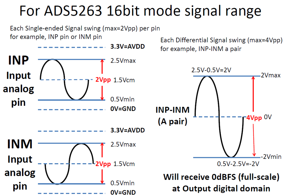
- Differential input voltage swing vs single-ended signal pk-pk voltage.
https://e2e.ti.com/support/applications/medical/f/30/t/541845
https://e2e.ti.com/support/applications/medical/f/30/t/494203
- What are the input reference clock jitter requirements for ADS52J90?
1ps typical jitter for clock source acceptable for the device.
http://www.ti.com/lit/an/slyt075/slyt075.pdf
- How to select the option to select the analog ADC inputs for AFE5809GUI, AFE5812GUI as opposed to test patterns?
Test pattern “none” means Analog signal input as opposed to ramp, sine, etc patterns.
- Why should we isolate the analog and digital power supplies?
Ideally, these supplies are kept separate to reduce risk of cross coupling from digital to analog domain. However, it can be done if care is taken in providing good power supply filtering close to each power DUT pin before combining to the central supply
https://e2e.ti.com/support/applications/medical/f/30/t/447944
- How to bias the AFE inputs when they are DC coupled?
We can’t externally bias our ADC inputs as they are already internally biased to a specific voltage.
https://e2e.ti.com/support/applications/medical/f/30/t/438972
- What is the maximum aperture delay per AFE channel and its contributing factors?
Typical aperture delay is specified in the corresponding device datasheet. It has both digital (clock skew between channels, device variation from lot-to-lot) and analog contributing factors (internal HP, LP filter variations in propagation delay).
https://e2e.ti.com/support/applications/medical/f/30/t/442040
- Please provide details about the 2-wire mode in ADS5294.
The ADS5294 is an 8 analog channel device therefore there are only 8 SMA's for the analog inputs. It is the digital output that can be used in 1-wire or 2-wire mode. In 1-wire mode there are 8 LVDS differential pairs corresponding to the 8 analog inputs. In 2-wire mode, there are 16 LVDS differential pairs with each analog input getting 2 outputs.
https://e2e.ti.com/support/applications/medical/f/30/t/426573
- Is it possible to connect AFE5801 to a PC and control setup using Labview?
The output of the AFE5801 is serial LVDS at 0.5Gbps or more. You would have to find a PC interface that can capture data that quickly.
https://e2e.ti.com/support/applications/medical/f/30/t/418052
- T/R switches for ultrasound
https://e2e.ti.com/support/applications/medical/f/30/t/394416
The TX810 is the only solution that our Medical Ultrasound team has for this type of application. It is our only T/R Switch.


