This thread has been locked.

If you have a related question, please click the "Ask a related question" button in the top right corner. The newly created question will be automatically linked to this question.

DLP6500FYE: EVM not working

Part Number: DLP6500FYE
Other Parts Discussed in Thread: DLPC900

Hi Team,

I need help with the troubleshooting of of the customers dlplcr6500evm.

Here is the background of the error:

I was using the DMD as usual. After having updated the LUT with a train of 36 images, the DMD have been stuck. I then put it in standby and switch the power of the EVM off (keeping the usb connected). After powering up again, the board is not communicating with the PC. I already tried different usb cables without fixing the issue. Now the DMD is reproducing the prestored patterns, leds on the board are on. But still I cannot communicate with any pc (I tried several ones)
The customer have tried the following:
- I unistalled all the GUI versions on my pc and reinstalled the 5.0. the firmware is also updated to version 6.0.0
- The board is not visible in Windows device manager when connected to the USB.
- The HDMI bus is detected by the pc as an external plug and play monitor.
- I disabled all the input and output trigger jumpers (J19-J21-J22-25).
Powering up the board, the D8 and D9 are ON and the D6 is is blinking, which indicates that the board is okay. however, once the EVM is plugged, nothing happens in the GUI. The status remain disconnected (red dot on the upper left). Also, the windows device manager don't see any device (known or not) plugged via USB.
We already tried the solution in the threads below bit the issue still persist. 
Can you please help?
Regrds,
Marvin
  • Thanks for the detailed report on the problem.  Please allows a day or so to develop some next thoughts to solve.

  • Marvin,

    Looking over the threads you reference it looks like you have already attempted to reload the bootloader.  Is that correct?  If so did the JTAG programming program report any error during the process?  Please reference DLPU101B [Single DLP Light Crafter Single DLPC900 EVM Guide] for the latest version of the Guide for this EVM(chipset).

    It sounds like the section of the bootloader that instantiates the USB interface is broken or the port is broken.  Are you able to check the USB lines for continuity?

    If you plug the USB into another computer and restart from scratch, does it see the USB?  

    Let me know so I can proceed with further debug.

    Fizix

  • Hi Fizix,

    There was no error during the last bootloader update (before this issue).

    I will provide you the result of the customer checking once he is done with the USB line probing.

    You have mentioned a broken section of the USB boot loarder. Can you please tell me which specific section this is?

    Thanks!

    Regards,

    Marvin

  • Marvin,

    Unfortunately, the bootloader is just code, so there is no "section" of the bootloader that I can point to.  I was referring to the code that is put in via JTAG when programming the bootloader.  The best way to see if this is true would be to reprogram the bootloader over JTAG.  But I think probing the USB line should come first.

    Checking the USB line is a good idea.  When that is complete, please report back with the results.

    Fizix

  • Hi Fizix,

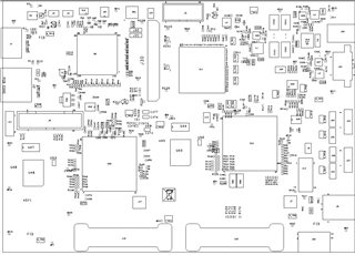
    The customer managed to check the connections. See the picture attached for reference.
    - USB Pin 2 is connected to D6
    - USB Pin 3 is connected to C5
    - USB Pin 4 is not connected to any pin on the DLPC900
    - USB Pin 1 s connected to many pins on the DLPC900. [A1,A2,A3,A17,A18,A24,A25,B1,B2,B3,B17,B18,B25,C18,C24,D23,D17,D18]

    With respect to my notation, you have to swap pins 1-4 and 2-3 (for the USB).
    So, I think the connection are good: 2-C5, 3-D6, 1 is mass and 4 is connected to the buffer (which I did not test!).

    also checked the connection between E25 on the DLPC900 and the pin 1 of the buffer (U12), and it seems fine.

    Can you tell me how to proceed next?

    Regards,

    Marvin

  • Marvin,

    The next step would be to use the USB-JTAG FTDI bridge shown in the DLP® LightCrafterTm Single DLPC900 Evaluation Module (EVM) User's Guide [DLPU101B].  Wire it as shown and follow the procedure which is section 3.11 JTAG Flash Programming starting on page 58.

    Fizix

  • Hello Marvin,

    Does this customer still need assistance with this?

    Fizix