- Ask a related questionWhat is a related question?A related question is a question created from another question. When the related question is created, it will be automatically linked to the original question.
This thread has been locked.
If you have a related question, please click the "Ask a related question" button in the top right corner. The newly created question will be automatically linked to this question.
This really is a continuation of https://e2e.ti.com/support/interface-group/interface/f/interface-forum/1085604/dp83867cr-phy-generating-rxdv-traffic-on-the-other-end-with-autonegotiate-turned-off/4018633#4018633 which must have gotten locked when I wasn't making updates.
I got back to testing this part. I have examined the TxEn line on the sender side and the RxDV on the receive. The scope shows no changes on the TxEn, but I still see activity on the RxDV. In that attached scope captures, the yellow is the RxDV, Blue is TxEn. This is across two different boards with teh DP83867CR. If I just loop my cable back on the same board, and look at these two signals on that board I do *not* see any activity on RxDV. We have added the 2.49k resistor on the RxDV line to set it to mode 4, as well as a pull-up to MDIO.
Hi Joshua,
Let me recap the observations from few months ago and get back to you in a day.
--
Regards,
Gokul.
Hi Joshua,
Can you please let me know the following?
--
Regards,
Gokul.
1.When looping back, the LED that flickers stays on solid (LED_0/Link). The flickering is only when connecting the two cards. I see Tx activity only when triggering a transmission for either case (loopback or two cards).
2. Yes. I do not see RxDv activity when I use a loopback cable.
3. I have about an 8 ft cable between the two cards with the DP83867. I've also tried a 50 ft, but I do not see a difference
4. I'm not sure you looked at the .tif files I attached. One of those show the RxDv pulses burst for about 235 uS, then pause . I did not measure the period between pulses. I can get that today.
I was able to get the link LED solid across two cards. Our set up is really a ring, and I was not completing it, I was only running from the tx of one end to the rx of the other card, but I was not running anything from the tx of the second card. Here is a little more of the schematic I had included from the other ticket that shows this:
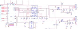
However, if I run the cables to a different phy I still cannot establish the link, even with the tx/rx plugged into both cards. The other phy is a DP83848 part.
Hi Joshua,
Can you please provide a register dump of 0x00 to 0x1F, 0x6E, 0x6F?
When you could get a solid LED link (without blinking), do you still see the same toggling behavior on RX_DV?
--
Regards,
Gokul.
Did you want the register dump for the connection to the other PHY? It's a bit of a pain because it's an FPGA connection with no processor, so it may take some gnarly vhdl code. I'm looking into what it would take.
I do not get the erroneous/unexpected RxDv activity when the link is established.
Hi Joshua,
I wanted to get that register to check if the link is stable. It seems that the RX_DV toggling when the link is dropping which usually happens during link drops.
Now that we don't see RX_DV toggling when the link is stable, can be stop looking at the RX_DV toggling issue? Are there any other problems you are facing?
I see that you have mentioned device not linking up with DP83848. Is this the only problem?
--
Regards,
Gokul.
The original issue was not linking up with the other phy (DP83848). The RxDv stuff was just something I noticed during troubleshooting that. I have a basic phy question: If the magnetics are inverted on one side (like the DP83848) would the encoding still work properly to establish the link?
Hi Joshua,
I couldn't completely get what you meant by magnetics inversion. It'll help me if you can send DP83848 board schematic and DP83867 board schematic and annotate on the schematic by what you meant on magnetics inversion?
You mentioned that now you are able to establish solid link. Between which link partners were you been able to achieve link?
Is the no link issue between DP83867 and DP83848 still present?
--
Regards,
Gokul.
Hi Joshua,
Are we using forced 100Base-TX mode for the link-up or are we letting the autoneg decide the speed?
--
Regards,
Gokul.
I've confirmed the Rx Clk is running at 25 MHz, so I think the MI settings are correct.
Hi Joshua,
Can you please let me know if AMDIX is enabled/disabled on both the PHYs?
Reverting back to my previous questions,
Which two PHYs have you been able to link up successfully?
What was the magnetics inversion you mentioned?
--
Regards,
Gokul.
Our new boards use the DP83867CR. I have been able to link two of these cards. I cannot establish the link to the DP83848. This older board looks to have its magnetics inverted if I am reading the schematic snippet I posted above with the yellow highlights.
Our DP83867 package does not have a RX_D6 pin to strap the AMDIX Disable, and I am not seeing its default in the datasheet, so I'm not sure.
Hi Joshua,
Can you please check if AMDIX is disabled on DP83848? AMDIX can be disabled by placing a strap resistor to ground. You can also read the register 19h[15] to check if it is enabled/disabled on DP83848.
--
Regards,
Gokul.
The AMDIX pin (rather, the Rx_ER) pin of the DP83848 does have a pull down. Here is a little wider shot of our DP83848 setup:
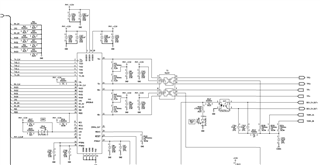
Hi Joshua,
AMDIX is disabled on DP83848. Can you please disable AMDIX on DP83867 by programming reg0x10[6:5] = 00?

--
Regards,
Gokul.
I've tried this (and it didn't change the link), but I think I need to add code to be able to read the various registers back to confirm (my speeds and whatnot change so I'm pretty sure they are 'taking' on the DP83867, but I haven't had the vhdl hooks to read the registers back).
My register settings: BMCR = X"2100"
CFG1 = X"0000"
CFG4 = X"0010"
PHYCR = X"0001"
Hi Joshua,
Can you please capture the waveforms on MDI of both the devices? This gives us an indication that force controls are working fine.
Please take a snapshot of the waveforms by zooming in at 8ns grid width and zooming out at 200ms grid size.
Please measure these waveforms using high impedance differential probe and after terminating the lines with 100ohms differential termination.
--
Regards,
Gokul.
Hey Gokul,
I was able to get register dumps for most of the addresses ( I did not do the extended ). These are the DP83867 registers. Here are the two registers that read differently when I have a good link (DP83867 hooked to another DP83867) and a failed link (DP83867 to DP83848):
| Register | Addr | Good Link | Failed Link |
| BMSR | 0x1 | 0x794d | 0x7949 |
| PHYSTS | 0x11 | 0x6C02 | 0x6802 |
I have the readings of all of the others if that helps as well. If these do not help I will try the waveform snapshot you asked for.
Thanks,
Joshua
Hi Joshua,
We will have to monitor TP0- and TP+.
Can you please share the raw logs of the registers you have collected too?
--
Regards,
Gokul.
Here are the other register settings. The waveforms will take a day or two.
| Register | Addr | Good Link | Failed Link |
| BMCR | 0x0 | 0x2100 | 0x2100 |
| BMSR | 0x1 | 0x794d | 0x7949 |
| PHYIDR1 | 0x2 | 0x2000 | 0x2000 |
| PHYIDR2 | 0x3 | 0xA231 | 0xA231 |
| ANAR | 0x4 | 0x01E1 | 0x01E1 |
| ANLPAR | 0x5 | 0x0000 | 0x0000 |
| ANER | 0x6 | 0x0064 | 0x0064 |
| ANNPTR | 0x7 | 0x2001 | 0x2001 |
| NNPTR | 0x8 | 0x0000 | 0x0000 |
| CFG1 | 0x9 | 0x0000 | 0x0000 |
| STS1 | 0xA | 0x0000 | 0x0000 |
| REGCR | 0xD | ||
| ADDAR | 0xE | ||
| 1KSCR | 0xF | 0x3000 | 0x3000 |
| PHYCR | 0x10 | 0x0001 | 0x0001 |
| PHYSTS | 0x11 | 0x6C02 | 0x6802 |
| MICR | 0x12 | 0x0000 | 0x0000 |
| ISR | 0x13 | 0x0400 | 0x0400 |
| CFG2 | 0x14 | 0x29C7 | 0x29C7 |
| RECR | 0x15 | 0x0000 | 0x0000 |
| BISCR | 0x16 | 0x0000 | 0x0000 |
| STS2 | 0x17 | 0x0040 | 0x0040 |
| LEDCR1 | 0x18 | 0x6150 | 0x6150 |
| LEDCR2 | 0x19 | 0x4444 | 0x4444 |
| LEDCR3 | 0x1a | 0x0002 | 0x0002 |
| CFG3 | 0x1E | 0x0002 | 0x0002 |
| CTRL | 0x1F | 0x0000 | 0x0000 |
Just to clarify the waveform, my highlighted nets above were on the connector side, you said to get TPO- and TPO+ (the tx side, connector side of the magnetics)?
Hi Joshua,
Sorry for the delayed response.
Can you please provide the register logs 0x00 to 0x1F for the DP83848 too in the passing and failure case?
By monitoring the lines using a differential probes, we need to ensure the following
--
Regards,
Gokul.
DP83867 has four differential pairs (A, B, C, D), but for this instance we are only using A and B. I assume that's what you mean re the TPO/TPI). I will set up monitoring those and grab the waveforms. Getting the registers for the 83848 is not really possible, it's on a stand alone board and since we cannot communicate with it I do not think it is available, nor do I think we can read it anyway (I have to get clarification from the guy who codes for that board).
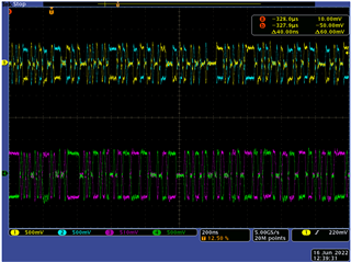
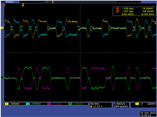
Hi Gokul, I'm having trouble finding 2 diff probes, still efforting. In the meantime, here are some grabs. The top waveforms (yellow and blue) are at the rx RJ45 pins of the schematic I snipped above, after about 4 ft of CAT5. The Green/Purple are the tx side (cable side, before the 4 ft of cat5). It's not quite the time scales you wanted, zooming out to 200 mS was just a haze. (edited: I realized my scope tap may have been shorting on my earlier capture)
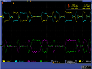
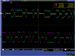
Hi Joshua,
We should be fine even if we have single ended probes. Can you please see if the following checklist is satisfied?
| S.No | Pins/Condition | Observations |
| 1 | DP83848 terminated with 100 ohms, no DP83867 connected, Transmitter outputs TPD+/-, | Continuous signaling observed When zoomed out to x-axis 200ms/unit, there still should be continuous signal and no gaps |
| 2 | DP83848 terminated with 100 ohms, no DP83867 connected, Receiver pins TPI+/- | Silent and no signal should be observed at all |
| 3 | DP83867 terminated with 100 ohms, no DP83848 connected, Channel A outputs, from J3A connector | Continuous signaling observed When zoomed out to x-axis 200ms/unit, there still should be continuous signal and no gaps |
| 4 | DP83867 terminated with 100 ohms, no DP83848 connected, Channel B, from J3B connector | Silent and no signal should be observed at all |
If the checklist is satisfied and we still can't achieve the link, we'll then read internal registers to DP83867 to check why we can't link up.
Please share your thoughts.
--
Regards,
Gokul.
Gokul, I put a 100 ohm between pins 1+2 of a short twisted pair, and plugged it into the four rj45s (1 tx, 1 rx per board due to our ring topology). Each observation matched what you stated above. What registers should I access and I assume this is with the boards plugged back into each other?
Hi Joshua,
Let me have a discussion with our team and get back to you.
--
Regards,
Gokul.
Hi Joshua,
Can you please read register 0x229 on DP83867?
In parallel, can you please check if registers can be made accessible on DP83848?
--
Regards,
Gokul.
I'm not 100% I got the sequence right, but if I did, address 0x229 = 0x0222. This is with the DP83867 wired as a ring to the DP83848. The DP83848 register access will be a bit of development work, it may take some time.
Hi Joshua,
Register 0x229 is an internal register.
Can you please read this register multiple times? Seems like 0x0222 is not expected.
The sequence is
000D,001F
000E,0229
000D,401F
Read 000E
--
Regards,
Gokul.
I'm pretty sure I did the sequence as you describe, but I'll repeat. However, I am out until July 12th, so it won't be until then. I did try the sequence with a loopback cable as well, and it also read 0x222, so it did not seem to be changing with the link status LED change-of-state. But my tool is a PCI Express memory access tool that accesses some configuration registers implemented in the FPGA to do the MI read/write. I did earlier read/writes with a integrated logic analyzer attached so i could verify the MDIO and MDC looked correct, but did not have it running for the register access to 0x229. I'll make sure I confirm the waveform along with the sequence next time (again it'll be a couple of weeks).
Thanks,
Joshua
How is this?
DP83867 wired as a ring to the DP83848: reg x229 = 0x00C4
DP83867 looped back to itself (externally, link shows good): 0x229 = 0x7CD4
Hi Joshua,
Please give me a day to go through this with our signal processing engineer and get back to you.
Can you please confirm that the read values are same if they are read multiple times?
--
Regards,
Gokul.
TheDP83867 wired as a ring to the DP83848 reads as 0x00C4 most of the time, but if I keep querying I occasionally see 0x00C5. Probably 1 out of 5 times I query is the 0xC5 value.
It stays at 0x7CD4 every time I read it for the loopback cable mode (the link LED is good in this case).
Hi Joshua,
Looks like there is energy detection on DP83867 from incoming signals of DP83848 transmit. But we don't see the signal processing converging and we are not sure whether the reception problem is with DP83848 or DP83867. Can you please let me know if are able to find a way to read registers of DP83848?
Can you please send me the schematics of DP83848 with the RJ45 connections? That part is missing in the schematic you have shared above.
Please confirm that for all the experiments, you are using the register settings reg0x10[6:5] = 00.
--
Regards,
Gokul.
We need to scope the effort on our end to read the DP83848 registers, it would require fpga and dsp updates on an older product, so it also would take a bit of research just to get the idea of the magnitude of the changes. It would probably be some weeks before that info would be available.
Hi Joshua,
Can you please share an image of the setup you have? I'd like to understand more about what DSR connectors mean and what DSR physical means?
Can you please let me know what is the cable length you are using?
--
Regards,
Gokul.