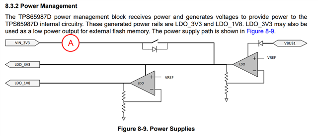
Part Number: TPS65987D
Other Parts Discussed in Thread: TPS65987, TPD6S300, BQ25792
Hi all,
After correcting the SPI connection to the flash from yesterday, I now have the Duo EVK source board supplying power to my board. However the problem now is that the internal PP_HV switches won't close. I have flashed on my board the Duo EVK sink's demo binary (tps65987_power_duo_mode_SINK_evm_flash_image.bin), so I expect it to behave the same. I have already swapped the flash on the Duo EVK sink with the flash from my board it can boot the EVK sink, and it does. Dumping the flash contents and comparing it to the programmed binary also shows they are the same. So I'm confident the image loaded on the flash is correct.
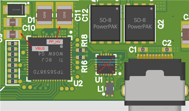
I have removed everything else on my board, so short of the FT4232HL programmer and the buttons/LEDs, it's (as far as I can tell) identical to the Duo EVK sink, save for the GPIOs which are currently just fanned out to test points.
There is also a TPD6S300 which I've unstuffed and bypassed - again just to eliminate any differences between my board and the Duo EVK sink.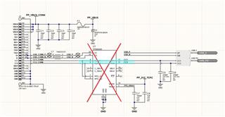
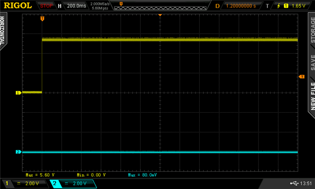
The problem is that I have 5V up to PP_VBUS, but PP_HV1/2 switches are not being closed. The Duo EVK source board's 5V LED also illuminates solid. Yesterday with the incorrectly connected flash, this was not happening. The EVK source 5V LED would briefly flash on and extinguish.
If I no-stuff the MISO pull-up to switch the boot strapping to BP_NoWait/Configuration 5, I get 20V on PP_VBUS and again nothing on PP_HVx. This to me suggests the controller is alive and negotiating contracts.
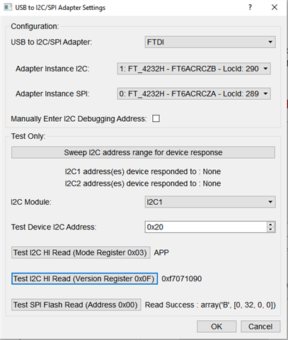
Inspecting the SPI activity at boot and comparing it to the Duo EVK sink, I don't see anything markedly different
Duo EVK sink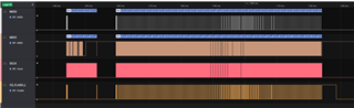
My board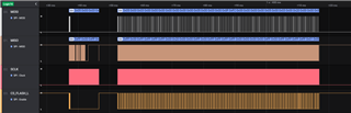
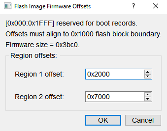
On my board, the CS line goes high when resting as I have a pull-up; the EVK sink does not. Inspecting the first and last few bytes - they match the programmed binary files starting at 0x2800 and ending at approx. 0x9A50, respectively.
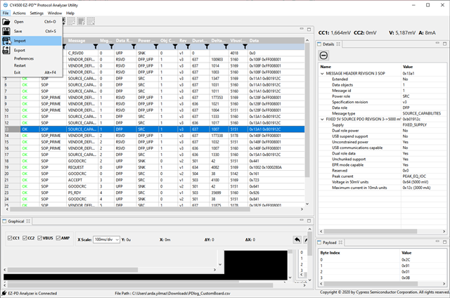
Comparing the CC activity, there is discrepancy between what the Duo EVK sink and my board is doing.
Duo EVK sink

My board
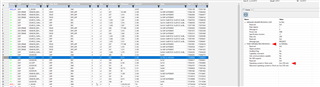
As you can see, my board only negotiates a Rev 2 RDO whereas the EVK sink is Rev 3. Additionally, mine asks for only un-enumerated current (100mA), while the EVK asks for 900mA~3A. The EVK also has almost double the transactions taking place after VBUS_UP (42 entries) compared to my board (28 entries).
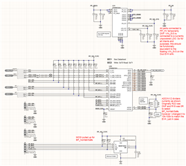
For convenience and my own sanity, below is an aggregated version of the EVK sink schematic. which I've annotated with highlighting for power nets and various buses.
TIA