This thread has been locked.

If you have a related question, please click the "Ask a related question" button in the top right corner. The newly created question will be automatically linked to this question.

TUSB1002: TUSB1002 SCH review

Part Number: TUSB1002

Hi Team

could you help me review the TUSB1002 SCH?

dt25_sff_x0_20240124_yenren_TUSB1002.pdf

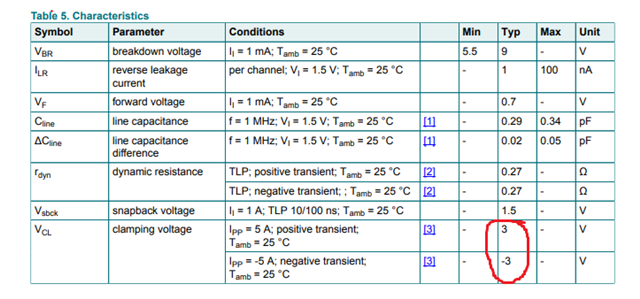
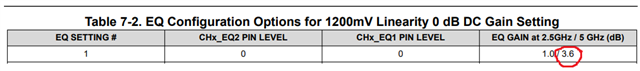
Could you also provide GAIN recommendation value?  all of them are FF

A to B is 4284

C to D FR4 length 1118

BRs

Brian

  • 1002A_Review.pdf

    Hi Brian,

    I've attached my review of the 1002A as a pdf. I can't see the connection from the 1002A to the connector, so I couldn't tell if there were issues on that end. Would you be able to show the routing to the USB connector?

    For EQ gain recommendations, can you clarify the position of the re-driver and  pre/post channel lengths:

    A to B is 4284

    C to D FR4 length 1118

    Is A to B the distance between the USB host and the 1002A? Can you provide the trace length in inches?

    Is C to D the trace length between the 1002A and the connector?

    Best,

    Shane

  • Hi Shane

    Is A to B the distance between the USB host and the 1002A? Can you provide the trace length in inches?

    YES,4.284 INCH


    Is C to D the trace length between the 1002A and the connector?

    1.118 INCH

    please see attached file for connector part 

    6327.dt25_sff_x0_20240124_yenren_TUSB1002.pdf

    BTW, do this part I should connect two caps here?

    BRs

    Brian

  • Hi Brian,

    BTW, do this part I should connect two caps here?

    No, you should only use one cap on each data line. In my original review I believed RX2P and RX2N went to the connector, but now I see they are to the host. It is ok to leave these as 100nF capacitors if they are the only capacitors between the 1002A and the host (see diagram below).

    Looking at the schematic, you need to change UC66 and UC67 to 330nF.

    I drew a diagram on how the AC coupling capacitors should look with relation to the host and connector side.

    I see the ESD diode you're using on the superspeed lines (AZ1023-04F) has a clamp voltage around 11V

    I recommend using a diode with a clamping voltage around 3V. A typical diode we recommend is the PUSB3FR4. You can see the characteristics below.

    Just to confirm you are operating at 5GHz correct? This would be 10Gbps.

    I estimated the loss from A to B at 5GHz as 3.39dB. (4.284in * 0.792 dB/in) With this in mind, you could use EQ setting 1 as a starting point.

    Estimating the loss from C to D at 5 GHz gives us 0.885dB. (1.118in * 0.792 dB/in) Using this number, with some loss from the cable, you could try EQ setting 1 to start here as well.

    Best,

    Shane

  • Hi Shane

    please see attached file 

    dt25_sff_x0_20240124_yenren_Cypress ACG1F 20240206.pdf

    there application frequency is 10GHz.

    BRs

    Brian

  • Hi Brian,

    I don't see the 1002A implementation in the schematic you've sent. I see two type-C connectors and PD controllers, when previously there was the 1002A connected to a type-A connector. Has the design changed?

    If you want to make a type-C port, you would need a MUX on the TX and RX pairs.

    As a side note: I saw the CC1/2 lines are swapped going into the PD controllers. If this is not intended then I recommend fixing these signals.

    Best,

    Shane

  • Hi Shane

    here is modified version SCH.

    dt25_sff_x0_20240124_yenren_TUSB1002 20240207.pdf

    BRs

    Brian

  • Hi Brian,

    As I mentioned before, you need to change the AC capacitors on the RX lines to 330nF between the 1002A and the connector.

    Otherwise, the schematic looks ok.

    Best,

    Shane

  • Hi Shane

    Many thanks for your review :)

    May I know why the Cap should be 330nF rather than other value.

    BRs

    Brian

  • Hi Brian,

    Hope you're doing well. Those capacitors need to be 330nF because the USB spec allows 75nF - 265nF of total capacitance on a USB signal line.

    When you consider that the transmitter side could have a capacitor around 100nF, you need to add a higher value capacitor on the receiver side or the total capacitance will drop below 75nF. This is because capacitors in series lower the total capacitance on the line.

    Best,

    Shane