This thread has been locked.
If you have a related question, please click the "Ask a related question" button in the top right corner. The newly created question will be automatically linked to this question.
Tool/software:
Hi support team,
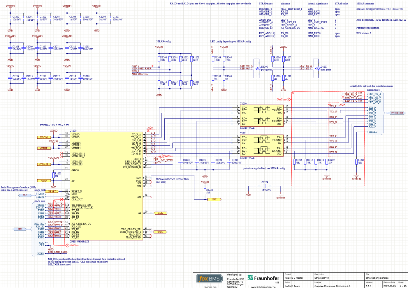
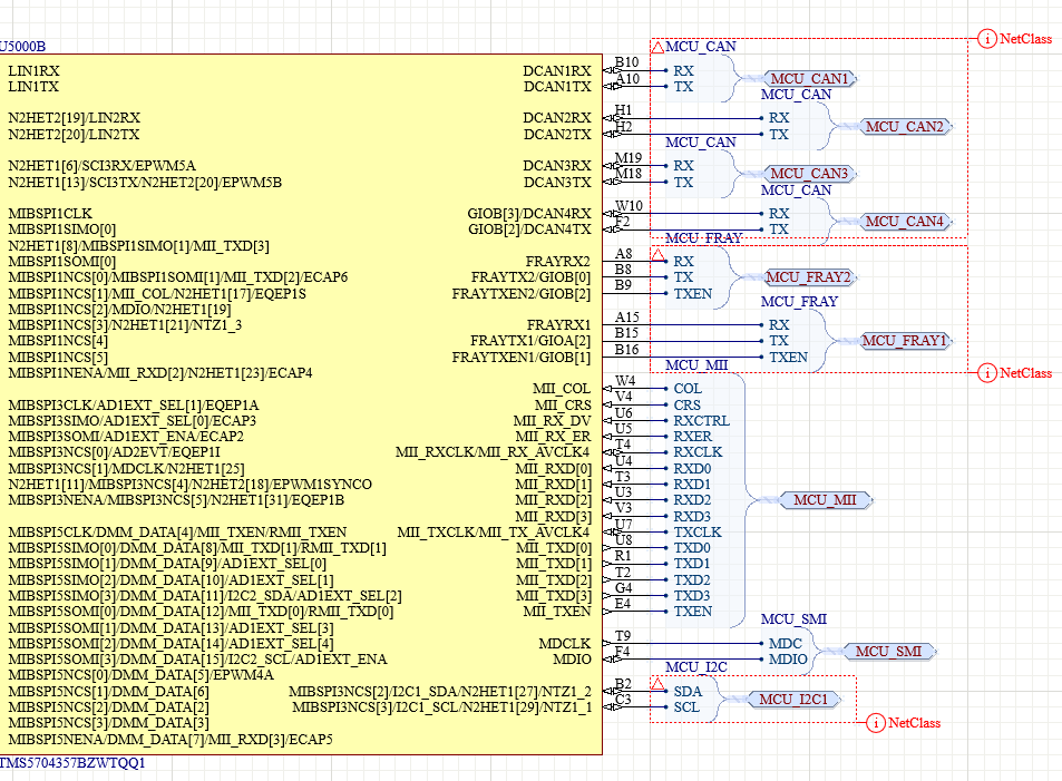
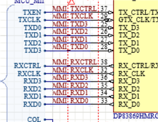
I am trying to integrate the DP83869HM in our FoxBMS (GitHub - foxBMS/foxbms-2: foxBMS 2, online documentation at https://docs.foxbms.org). There we are facing some issues in the MII to copper connection between the PHY and TMS570LC4357. We are not receiving any interrupts on the MAC side in the RXINTSTATRAW register when pinging it via a pc. For the configurationm we are currently using a modified version of the lightweight IP (lwIP) demo (http://git.ti.com/hercules_examples/hercules_examples/trees/master/Application/LwIP)
The MDIO registers show the PHY alive and with link on address 0x00.
The register configuration is as follows:
0x0 BMCR = 0x1140,
0x1 BMSR = 0x796D,
0x2 PHYIDR1 = 0x2000,
0x3 PHYIDR2 = 0xA0F1,
0x4 ANAR = 0x01E1,
0x5 ALNPAR = 0xCDE1,
0x6 ANER = 0x6F,
0x7 ANNPTR = 0x2001,
0x8 ANLNPTR = 0x4006,
0x9 GEN_CFG1 = 0x0,
0xA GEN_STATUS1 = 0x0800,
0xD REGCR = 0x401F,
0xE ADDAR = 0x60,
0xF 1KSCR = 0xF000,
0x10 PHY_CONTROL = 0x5048,
0x11 PHY_STATUS = 0x7C02,
0x12 INTERRUPT_MASK = 0x0,
0x13 INTERRUPT_STATUS = 0x1C42,
0x14 GEN_CFG2 = 0x29C7,
0x15 RX_ERR_CNT = 0x0,
0x16 BIST_CONTROL = 0x0,
0x17 GEN_STATUS2 = 0x40,
0x18 LEDS_CFG1 = 0x6150,
0x19 LEDS_CFG2 = 0x4404,
0x1A LEDS_CFG3 = 0x2,
0x1E GEN_CFG4 = 0x12,
0x1F GEN_CTRL = 0x0
We also do the op mode setting in 0x01DF = 0x0060 and make afterwards the software restart with 0x001F=4000.
Is there anything else we might have missed?
kind regards,
Sven
Hi Sven,
Please share the register address and bit that is being referenced in the code for RXINTSTATRAW.
Are you expecting this interrupt to flag during ping, in the event of no errors with communication?
Thank you,
Evan
Hi Evan,
thank you for your quick response.
It is register FCF7 80A0h and I'm also looking at bit 0.
In my reference setup with the Launchpad XL2 (Same processor, different PHY) I get there the interrupt. As seen in the debug output.
With the DP83869 I never have interrupts at this point.
Regards,
Sven
Hi Sven,
Do you have any test points for MAC traces? I would like to verify the MAC is receiving data, as I believe RXINTSTATRAW should increment on any data input.
Could the schematic also be shared so I may review MAC connections? (can email to e-mayhew@ti.com for private share)
Is LED_1/RX_ER of the PHY connected to MAC, and muxed with PHY register 0x18 = 0xE? This pin is optional, but it's not clear if it will have an effect on MAC's interrupt register. If possible, please check if RX_ER is connected in the working case with the different PHY.
Thank you,
Evan
Hi Evan,
I checked the LED_1/RX_ER pin. It is connected to the MAC and I configured the register to 0xE0 as LED_1/RX_ER is configured through bits 7-4, right? This has no effect. In the case of the different PHY the RX_ER is also connected.
Here are the relevant parts of the schematic:
The complete schematic is also available here:
Hi Sven,
The MAC TX lines seems to have inverted mapping here (TXD3 of MAC = TXD0 of PHY):
I suspect this is the cause of the MAC not receiving valid data to flag the interrupt.
Can these lines be internally muxed on the MAC-side to accommodate this mapping?
Thank you,
Evan
Hi Evan,
Oh yes, that could explain the problem. Unfortunately there is no possibility to change the muxing for it internally. We try to change the line mapping and look then for the results.
Thank you,
Sven
Hi Sven,
Sounds good. Please reach out for any questions in the meantime.
Thank you,
Evan
Hi Evan,
meanwhile, I found a way to connect the processor and the DP83869 correctly. I connected the DP83869 board with jumper wires accordingly and I got the receive interrupt.
However, the data seems to be wrong. When I send a ping signal I expect the ICMP type + code 0x0800 in the message header. This is also the case in my working assembly. In the other assembly, I get the type 0x0000.
When I probe the signals, the clock looks a bit wired at the beginning of the transmission. I reduced the RX clock frequency to 2.5MHz to have a more clear picture. See below:
Ch0 - Clock
Ch1 - RXD0
Ch2 - RXD1
Ch3- RXD2
Ch4 - RXD3
Kind regards,
Sven
Hi Sven,
Do you see EtherType = 0x0 in the frame's signal, or is this how the MAC is interpreting the frame?
In the latter case, this is likely due to signal integrity / timing due to jumper connections on the MAC signals.
Please see if the connections can be adjusted for a cleaner signal, and if type 0x0800 can be seen in any iteration.
Thank you,
Evan
Hi Evan,
I looked into the signal line. On the line the data is transfered correctly. However, when I look into the memory or the MAC where the buffer descriptor is pointing, I find the meta data like the packet lenght and flags, but not the payload. It is always empty. I'm currently looking in the software why that is the case.
Kind regards,
Sven
Hi Sven,
Thanks for confirming.
As the signal has the correct EtherType, the issue seems to be with how MAC is sampling the data on receiver. I suggest testing at 10M for less marginality with hotwired connections.
MII loopback is another option if there are doubts about the signal quality on the MDI side. This can be achieved with 0x16[2] = '1'.
If sending data from MAC to PHY and looping directly back to MAC, do you see any difference in how the MAC interprets the frame?
Thank you,
Evan
Hi Evan,
I reduced the data rate to 10M, as you suggested.
When I try MII loopback, I don't get any response. The code for sending the packet is working as I tried it on the Launchpad configuration.
I think the problem is in the sending process. After calling the HALCoGen generated EMACTransmit function, I never get to the EMACTxIntHandler function. When I look in the head descriptor pointer registers, the pointer for TX0HDP doesn't get resettet. Could the problem lay in the different pinmux configuration here?
Kind regards,
Sven
Hi Sven,
Do you see data on both TX and RX MAC lines when probing with PHY loopback enabled?
I can help debug on the PHY-side, but my familiarity with the BMS SW is limited.
Tagging TMS team to see if there are suggestions to debug MAC transmit/receive functions or pinmux config.
Please share the pinmux configuration settings for review.
Thank you,
Evan
Hi Evan,
No I just see the clock signal. Thank you that would be very helpful. I attached my source code including the HALCoGen config. I noticed that the phy address gets hard coded by the HALCoGen in the EMACInstConfig function. I already changed that to the correct address.
Kind regards,
Sven
Hi Sven,
Do you see indication that the MAC recognizes the PHY on the port? As you have shown scope-shots of MAC lines for data sent from a link partner, I suspect the cause is on the MAC-side SW config for this board.
Thank you,
Evan
Hi Evan,
I tried a few things in the meantime. There I noticed that the PHY hangs up at some point.
When starting the program after a power cycle of the PHY, the ping signal gets passed trough and the MAC interrupt register indicates an interrupt.
I monitored this trough the program flow. It stops working when i configure the loopback mode. To be precise when I write 0x16[2] = '1' as you said. After this command the ping signal is not passed trough anymore and also the link status register is not updated anymore (I unplugged the RJ45 and plugged it in again). Here is the code I use for configuring the loopback mode:
boolean Dp83869EnableLoopback(uint32 mdioBaseAddr, uint32 phyAddr) { uint32 delay = 0x1FFFU; uint16 regVal = 0x0000U; uint16 *regPtr = ®Val; boolean retVal = TRUE; (void)MDIOPhyRegRead(mdioBaseAddr, phyAddr, (uint32)PHY_BMCR, regPtr); /* Disabling Auto Negotiate. */ regVal &= (uint16)(~((uint16)PHY_AUTONEG_ENABLE)); MDIOPhyRegWrite(mdioBaseAddr, phyAddr, (uint32)PHY_BMCR, regVal); /* When configuring loopback modes, the Loopback Configuration Register (LOOPCR), address 0x00FE, should be set to 0xE720. */ Dp83869ExtendedAddressSpaceRegWrite(mdioBaseAddr,phyAddr,0x00FE,0xE720); /* In 100Base-TX mode after MII loopback is enabled through register 0x00, it is necessary to write 0x0004 to register 0x16 for proper operation of MII Loopback*/ MDIOPhyRegRead(mdioBaseAddr, phyAddr, (uint32)PHY_BIST, regPtr); /* Enable External Loopback*/ regVal |= 0x4; MDIOPhyRegWrite(mdioBaseAddr, phyAddr, (uint32)PHY_BIST, regVal); if(MDIOPhyRegRead(mdioBaseAddr, phyAddr, (uint32)PHY_BIST, regPtr) != TRUE) { retVal = FALSE; } return retVal; }
Do you know any explanation for this behavior?
Kind regards,
Sven
Hi Sven,
Is any other part of the application code dependent on MDI-side link up?
Enabling loopback will cause link down on the MDI side, as only MAC<->PHY communication is possible with this config.
In this case, it's possible there is some logic in the application SW that requires link status high to continue with transmission.
Thank you,
Evan
Hi Evan,
I don't think that is the case. The code works with the dp83630 on the Launchpad fine. In that case the MDI communication still works: is that different between the PHYs?
My problem is that the interrupt for the transmission as I mentioned earlier. I added my current configurations. If you or some from the TMS Team could verify it that would be very helpful.
Best regards,
Hi Sven,
This is the same loopback code running 0x16[2] = '1' on DP83640?
The register map for DP83640 is different from DP83869. 0x16[2] = '1' will not enable loopback on 640, so MDI communication is still possible here.
I monitored this trough the program flow. It stops working when i configure the loopback mode. To be precise when I write 0x16[2] = '1' as you said. After this command the ping signal is not passed trough anymore and also the link status register is not updated anymore (I unplugged the RJ45 and plugged it in again).
Is the program generating / expecting a ping response while connected to a link partner? If so, this is not expected to work when enabling loopback. The code for loopback test should only check the MAC transmission path without link-up on the MDI-side.
I've notified TSM team of this query, hoping they can review and share feedback here.
Thank you,
Evan
Hi Evan,
for the DP83630 I use the default HalCoGen code for the DP63640. There it is register 0x0 (BMCR) = 0x4000. Then the loopback works and MDI communication is still possible.
Maybe I summarize my procedure here a bit as it got quite complex. My goal is to use the DP83869 on our foxBMS. In a first step I want it to answer a ping signal. Therefore, I had meanwhile 3 different hardware combinations: The Launchpad XL2 and the onboard DP63630, the foxBMS-Master with the DP83869 and, the Launchpad XL2 in combination with the DP83869EVM eval board. On these platforms I tried to run two software bases; the lightweight IP (lwIP) demo and EMAC Loopback TxRx example. I modified them accordingly to the different platforms.
On the Launchpad XL2:
On the foxBMS-Master:
On the Launchpad XL2 in combination with the DP83869EVM:
/* Make sure that the transmission is over */ while((hdkif_swizzle_data(curr_bd->flags_pktlen) & EMAC_BUF_DESC_OWNER)
/* Wait for the EOQ bit is set */ /*SAFETYMCUSW 28 D MR:NA <APPROVED> "Hardware status bit read check" */ /*SAFETYMCUSW 134 S MR:12.2 <APPROVED> "LDRA Tool issue" */ /*SAFETYMCUSW 45 D MR:21.1 <APPROVED> "Valid non NULL input parameters are assigned in this driver" */ while (EMAC_BUF_DESC_EOQ != (EMACSwizzleData(curr_bd->flags_pktlen) & EMAC_BUF_DESC_EOQ)) { }
So I have two quite different approaches that lead to a similar behavior. I hope this clarifies my procedure a bit.
Is the program generating / expecting a ping response while connected to a link partner? If so, this is not expected to work when enabling loopback. The code for loopback test should only check the MAC transmission path without link-up on the MDI-side.
The program is not expecting a ping. I just noticed that when using nearly the same code, the DP83630 is passing the ping signal all the time on the MII and the DP86869 does not. After enabling loopback also the MII clock rate gets reset to 25 MHz and the unplugging of the RJ45 plug gets not indicated anymore. That led me to the conclusion, that the PHY hung up. To put it short I just used the ping in that situation to check if the PHY is still alive. If in loopback mode the MDI side is down on this PHY of course this could not be an indication.
Thank you and best regards,
Sven
Hi Sven,
Thanks for sharing the summary of each test case.
Focusing on the DP83869 loopback case, MII clock rate is dependent on the speed of MDI connection. With auto-negotiation enabled, this will default to highest clock rate (25M) until the PHY can link on MDI-side and adjust clock rate depending on link speed.
Disabling auto-negotiation (0x0[12] = '0') and forcing the speed to 10M (0x0[13,6] = '00') should keep the clock at 2.5M.
Do you see TX interrupt after setting forced speed for 10M loopback test?
Thank you,
Evan
Hi Evan,
I have disabled auto negotiation via strapping. Then in my code, first I disable auto negotiation again. After that the speed is forced to 10M. When I then enable loopback the speed gets reset to 25 MHz.
If I then force it again to 10M /2.5MHz it takes several seconds to change, but then it switches back.
And no, in none of these cases I see the TX interrupt.
Kind regards,
Sven
Strange, it looks like the SW is overwriting the register configuration. As the clock resets to 25MHz, we can focus on loopback case for 100M speed.
Can you help verify the MAC-side configuration is set for 100M in MII? After forcing the speed in 100M on the PHY-side and still no data frames are observed on MAC TX/RX lines, it seems the MAC-side setting is not being set properly for MII.
Thank you,
Evan
Hi Evan,
as the PHY provides the Tx and Rx clock signal, I don't think there is a separate setting for the different speed modes on the MAC module.
Best regards,
Sven
Hi Sven,
I'm not clear on the MAC-side requirements for valid transmission. I have pinged TSM team again to see if there is feedback they can share.
From the PHY-side, the configuration and HW connections are valid for communication.
Thank you,
Evan
Hi Sven,
Not yet, I have contacted them again.
Apologies for the delay here.
Thank you,
Evan
Hi Evan,
In the meantime we fixed the problem by ourselves. Thank you for your support over the time.
Kind regards,
Sven
Hi Sven,
Glad to hear you found a fix. Could you please share what the root cause was, if it was on the PHY-side or a software fix?
Thank you,
Evan
Hi Evan,
the MII_COL signal of the PHY was left floating and not connected to GND. That seems to cause the issues.
Kind Regards,
Sven