


Hello experts,
I got general question of maximum input capacitor value for CMOS logic (e.g. HC, AHC, HCT family) input pin.
Sometimes, we add capacitor at input pin for delay, decoupling noise...
How much input capacitor can we add for TI's CMOS logic IC in generally?
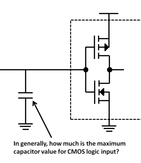
In other vender's app note, it is described that 500pF is limit for direcect connecting capacitor.
If over 500pF capacitor is added, current limit resistor (100~1kohm) is required. Latch up may be occurred.
If you have good app note or tech document, could you tell me?
Thanks and best regards,
Ryo Akashi

