
- Ask a related questionWhat is a related question?A related question is a question created from another question. When the related question is created, it will be automatically linked to the original question.
This thread has been locked.
If you have a related question, please click the "Ask a related question" button in the top right corner. The newly created question will be automatically linked to this question.
Hi Team,
I have custom AM2434_ALV processor connected with 4GB DDR4, pin configuration is same as AM2434 EVM board.
I have following question regarding DDR4
Please guide me.
--
Thanks & Regards,
Divyesh Patel
Hi Divyesh,
The DDR initialization in the gel file is for the DDR (8MB) used on the AM243x EVM. You may need to adjust it according to the size, timing etc. for the DDR used on your custom board. The file does the DDR initialization for AM243x EVM is at
C:\ti\ccs1200\ccs\ccs_base\emulation\gel\AM24x\AM24_DDRSS\AM24x_GP_EVM.gel
Best regards,
Ming

Hi Ming,
Thank you for your message.
Could you please provide me some procedures or references?
It will be very helpful for me.
—
Thanks & Regards,
Divyesh Patel
Hi Divyesh,
The DDR4 configuration tools and documentation are not in ideal situation. Here is what we have so far:
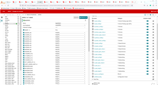
1. Go to SysConfig (ti.com) and add a new DDR4 instance
2. Use the generated AM243x-DDRConfig.gel to replace the C:\ti\ccs1200\ccs\ccs_base\emulation\gel\AM24x\AM24_DDRSS\AM24x-DDR4-1600MTs.gel
3. re-run the load_dmdsc.js and the AM2434_EVM DDR script.
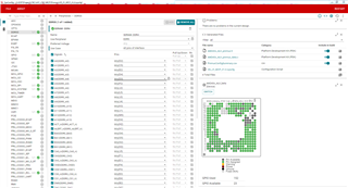
You can also adjust the following:
1. DDR Memory Type
2. System Configuration
3. DRAM Timing A/B
4. IO Control A/B
Best regards,
Ming
Hi Ming,
Thank you for your guidance.
I am using ccs1110, does it work with it?
or need to go with ccs1200?
—
Thanks & Regards,
Divyesh Patel
Hi Ming,
I referred "https://software-dl.ti.com/mcu-plus-sdk/esd/AM243X/08_05_00_24/exports/docs/api_guide_am243x/DRIVERS_DDR_PAGE.html" for the DDR configuration.
Tried all 3 methods using

but i am not able to generate .gel file
How to generate .gel file? Please guide what wrong steps i have done.
--
Thanks & Regards,
Divyesh Patel
Hi Divyesh,
It should work for CCS 11.1 too. Please try the steps I suggested in previous post:
---------------------------
The DDR4 configuration tools and documentation are not in ideal situation. Here is what we have so far:
1. Go to https://dev.ti.com/sysconfig/?product=Processor_DDR_Config&device=AM243x_beta and add a new DDR4 instance:
2. Use the generated AM243x-DDRConfig.gel to replace the C:\ti\ccs1200\ccs\ccs_base\emulation\gel\AM24x\AM24_DDRSS\AM24x-DDR4-1600MTs.gel
3. re-run the load_dmdsc.js and the AM2434_EVM DDR script.
You can also adjust the following:
1. DDR Memory Type
2. System Configuration
3. DRAM Timing A/B
4. IO Control A/B
-----------------------------
Best regards,
Ming
Hi Ming,
I have created .gel file and replaced in the given link
Use the generated AM243x-DDRConfig.gel to replace the C:\ti\ccs1200\ccs\ccs_base\emulation\gel\AM24x\AM24_DDRSS\AM24x-DDR4-1600MTs.gel
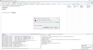
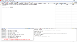
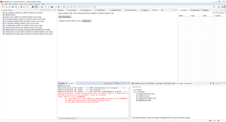
Then run script from Scripts->AM24 DDR Initialization -> AM24 DDR Initialization DDR Enabled/ Disabled both, but still stuck as per the attached image
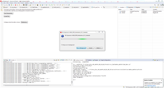
and 2nd time its got failed as per the attached image
I have even tried with TMDS243GPEVM, with the default SDK configuration, still getting issue
Please guide me.
--
Thanks & Regards,
Divyesh Patel
Hi Divyesh,
The DDR4 configuration is very complicated, and it is highly dependent to the DDR4 you used.
Have you adjusted the DDR4 settings according to your DDR4 chip when you use https://dev.ti.com/sysconfig/?product=Processor_DDR_Config&device=AM243x_beta?
For AM243x GP EVM, you may try it with the latest MCU+ SDK 08.05.00.24 and CCS12.
Best regars,
Ming
Hi Ming,
Thank you for your response.
Have you adjusted the DDR4 settings according to your DDR4 chip when you use https://dev.ti.com/sysconfig/?product=Processor_DDR_Config&device=AM243x_beta?
Yes, I have done all configuration according to the my DDR4 chip.
I will try with CCS1200.
One more confusion is i have tried with EVM but in that also getting error
I have even tried with TMDS243GPEVM, with the default SDK configuration, still getting issue
why its so?
It should work with EVM bcz SDK is configured according to the EVM, then why it’s getting error
Please help me regarding this , it may give me some hint for my problem.
—
Thanks & Regards,
Divyesh Patel
Hi Divyeh,
I think it may be related to the target configuration file and the load_dmsc.js. I tried CS12.0.0 with MCU+ SDK 08.04.00.17 for AM64x using AM64x GP EVM instead of AM243 GP EVM as the default target configuration. It works properly with the following script:
loadJSFile "C:/ti/mcu_plus_sdk_am64x_08_04_00_17/tools/ccs_load/am64x/load_dmsc.js"
followed by the DDR initialization.
By the way the AM243x GP EVM an AM64x G EVM are the same physically.
Best regards,
Ming
Hi Ming,
I have successfully completed DDR initialization test, Write and Read test with AM2434 EVM.
But in my custom board, initialization & write test is done but unable to complete read test.
Please check my log and help me out.
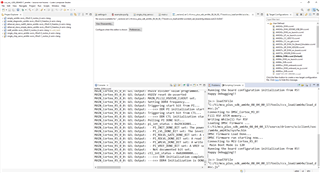
DMSC_Cortex_M3_0: GEL Output: This GEL is currently only supported for use from the Cortex-M3 inside the DMSC.
DMSC_Cortex_M3_0: GEL Output: Do not run this GEL from any other CPU on the SoC.
DMSC_Cortex_M3_0: GEL Output: This script sets the first address translation region to [0x8000_0000, 0x0000_0000].
DMSC_Cortex_M3_0: GEL Output: It also sets the second address translation region to    [0x6000_0000, 0x4000_0000].
DMSC_Cortex_M3_0: GEL Output: This is consistent with the SoC DV assumptions.
DMSC_Cortex_M3_0: GEL Output: Configuring ATCM for the R5Fs
DMSC_Cortex_M3_0: GEL Output: ATCM Configured.
DMSC_Cortex_M3_0: GEL Output: R5F Halt bits set.
DMSC_Cortex_M3_0: GEL Output: Configuring bootvectors
DMSC_Cortex_M3_0: GEL Output: Bootvectors configured.
DMSC_Cortex_M3_0: GEL Output: Programming all PLLs.
DMSC_Cortex_M3_0: GEL Output: Programming Main PLL 0 (Main PLL)
DMSC_Cortex_M3_0: GEL Output: Main PLL 0 (Main PLL) Set.
DMSC_Cortex_M3_0: GEL Output: Programming Main PLL 1 (Peripheral 0 PLL)
DMSC_Cortex_M3_0: GEL Output: Main PLL 1 (Peripheral 0 PLL) Set.
DMSC_Cortex_M3_0: GEL Output: Programming Main PLL 2 (Peripheral 1 PLL)
DMSC_Cortex_M3_0: GEL Output: Main PLL 2 (Peripheral 1 PLL) Set.
DMSC_Cortex_M3_0: GEL Output: Programming Main PLL 8 (ARM0 PLL)
DMSC_Cortex_M3_0: GEL Output: Main PLL 8 (ARM0 PLL) Set.
DMSC_Cortex_M3_0: GEL Output: Programming Main PLL 12 (DDR PLL)
DMSC_Cortex_M3_0: GEL Output: Main PLL 12 (DDR PLL) Set.
DMSC_Cortex_M3_0: GEL Output: Programming Main PLL 14 (Main Domain Pulsar) PLL)
DMSC_Cortex_M3_0: GEL Output: Main PLL 14 (Main Domain Pulsar PLL) Set.
DMSC_Cortex_M3_0: GEL Output: Programming MCU PLL 0 (MCU PLL)
DMSC_Cortex_M3_0: GEL Output: MCU PLL 0 (MCU PLL) Set.
DMSC_Cortex_M3_0: GEL Output: All PLLs programmed.
DMSC_Cortex_M3_0: GEL Output: Powering up all PSC power domains in progress...
DMSC_Cortex_M3_0: GEL Output: Powering up MAIN domain peripherals...
DMSC_Cortex_M3_0: GEL Output: Powering up GP_CORE_CTL.
DMSC_Cortex_M3_0: GEL Output: Powering up LPSC_DMSC
DMSC_Cortex_M3_0: GEL Output: No change needed.
DMSC_Cortex_M3_0: GEL Output: Powering up LPSC_MAIN_TEST
DMSC_Cortex_M3_0: GEL Output: No change needed.
DMSC_Cortex_M3_0: GEL Output: Powering up LPSC_MAIN_PBIST
DMSC_Cortex_M3_0: GEL Output: No change needed.
DMSC_Cortex_M3_0: GEL Output: Powering up LPSC_EMMC_4B
DMSC_Cortex_M3_0: GEL Output: Power domain and module state changed successfully.
DMSC_Cortex_M3_0: GEL Output: Powering up LPSC_EMMC_8B
DMSC_Cortex_M3_0: GEL Output: Power domain and module state changed successfully.
DMSC_Cortex_M3_0: GEL Output: Powering up LPSC_USB
DMSC_Cortex_M3_0: GEL Output: Power domain and module state changed successfully.
DMSC_Cortex_M3_0: GEL Output: Powering up LPSC_ADC
DMSC_Cortex_M3_0: GEL Output: Power domain and module state changed successfully.
DMSC_Cortex_M3_0: GEL Output: Powering up LPSC_DEBUGSS
DMSC_Cortex_M3_0: GEL Output: No change needed.
DMSC_Cortex_M3_0: GEL Output: Powering up LPSC_GPMC
DMSC_Cortex_M3_0: GEL Output: Power domain and module state changed successfully.
DMSC_Cortex_M3_0: GEL Output: Powering up LPSC_EMIF_CFG
DMSC_Cortex_M3_0: GEL Output: Power domain and module state changed successfully.
DMSC_Cortex_M3_0: GEL Output: Powering up LPSC_EMIF_DATA
DMSC_Cortex_M3_0: GEL Output: Power domain and module state changed successfully.
DMSC_Cortex_M3_0: GEL Output: Powering up LPSC_MCAN_0
DMSC_Cortex_M3_0: GEL Output: Power domain and module state changed successfully.
DMSC_Cortex_M3_0: GEL Output: Powering up LPSC_MCAN_1
DMSC_Cortex_M3_0: GEL Output: Power domain and module state changed successfully.
DMSC_Cortex_M3_0: GEL Output: Powering up LPSC_SA2UL
DMSC_Cortex_M3_0: GEL Output: No change needed.
DMSC_Cortex_M3_0: GEL Output: Powering up LPSC_SERDES_0
DMSC_Cortex_M3_0: GEL Output: Power domain and module state changed successfully.
DMSC_Cortex_M3_0: GEL Output: Powering up LPSC_PCIE_0
DMSC_Cortex_M3_0: GEL Output: Power domain and module state changed successfully.
DMSC_Cortex_M3_0: GEL Output: Powering up GP_CORE_CTL done.
DMSC_Cortex_M3_0: GEL Output: Powering up PD_PULSAR_0.
DMSC_Cortex_M3_0: GEL Output: Powering up LPSC_PULSAR_0_R5_0
DMSC_Cortex_M3_0: GEL Output: No change needed.
DMSC_Cortex_M3_0: GEL Output: Powering up LPSC_PULSAR_0_R5_1
DMSC_Cortex_M3_0: GEL Output: Power domain and module state changed successfully.
DMSC_Cortex_M3_0: GEL Output: Powering up LPSC_PULSAR_PBIST_0
DMSC_Cortex_M3_0: GEL Output: Power domain and module state changed successfully.
DMSC_Cortex_M3_0: GEL Output: Powering up PD_PULSAR_0 done.
DMSC_Cortex_M3_0: GEL Output: Powering up PD_PULSAR_1.
DMSC_Cortex_M3_0: GEL Output: Powering up LPSC_PULSAR_1_R5_0
DMSC_Cortex_M3_0: GEL Output: Power domain and module state changed successfully.
DMSC_Cortex_M3_0: GEL Output: Powering up LPSC_PULSAR_1_R5_1
DMSC_Cortex_M3_0: GEL Output: Power domain and module state changed successfully.
DMSC_Cortex_M3_0: GEL Output: Powering up LPSC_PULSAR_PBIST_1
DMSC_Cortex_M3_0: GEL Output: Power domain and module state changed successfully.
DMSC_Cortex_M3_0: GEL Output: Powering up PD_PULSAR_1 done.
DMSC_Cortex_M3_0: GEL Output: Powering up PD_ICSSG_0.
DMSC_Cortex_M3_0: GEL Output: Powering up LPSC_ICSSG_0
DMSC_Cortex_M3_0: GEL Output: Power domain and module state changed successfully.
DMSC_Cortex_M3_0: GEL Output: Powering up PD_ICSSG_0 done.
DMSC_Cortex_M3_0: GEL Output: Powering up PD_ICSSG_1.
DMSC_Cortex_M3_0: GEL Output: Powering up LPSC_ICSSG_1
DMSC_Cortex_M3_0: GEL Output: Power domain and module state changed successfully.
DMSC_Cortex_M3_0: GEL Output: Powering up PD_ICSSG_1 done.
DMSC_Cortex_M3_0: GEL Output: Powering up PD_CPSW.
DMSC_Cortex_M3_0: GEL Output: Powering up LPSC_CPSW3G
DMSC_Cortex_M3_0: GEL Output: Power domain and module state changed successfully.
DMSC_Cortex_M3_0: GEL Output: Powering up PD_CPSW done.
DMSC_Cortex_M3_0: GEL Output: Powering up all MAIN domain peripherals done.
DMSC_Cortex_M3_0: GEL Output: Powering up MCU Domain peripherals.
DMSC_Cortex_M3_0: GEL Output: Powering up GP_CORE_CTL_MCU.
DMSC_Cortex_M3_0: GEL Output: Powering up LPSC_TEST
DMSC_Cortex_M3_0: GEL Output: No change needed.
DMSC_Cortex_M3_0: GEL Output: Powering up LPSC_MAIN2MCU
DMSC_Cortex_M3_0: GEL Output: No change needed.
DMSC_Cortex_M3_0: GEL Output: Powering up LPSC_MCU2MAIN
DMSC_Cortex_M3_0: GEL Output: No change needed.
DMSC_Cortex_M3_0: GEL Output: Powering up GP_CORE_CTL_MCU done.
DMSC_Cortex_M3_0: GEL Output: Powering up PD_M4F.
DMSC_Cortex_M3_0: GEL Output: Powering up LPSC_M4F
DMSC_Cortex_M3_0: GEL Output: Power domain and module state changed successfully.
DMSC_Cortex_M3_0: GEL Output: Powering up PD_M4F done.
DMSC_Cortex_M3_0: GEL Output: Powering up MCU Domain peripherals done.
DMSC_Cortex_M3_0: GEL Output: Powering up all PSC power domains done!
DMSC_Cortex_M3_0: GEL Output:
DMSC_Cortex_M3_0: GEL Output: M4F WFI Vector set into IRAM.
MAIN_Cortex_R5_0_0: GEL Output: Running from R5
MAIN_Cortex_R5_0_0: GEL Output:

DDR not initialized with R5 connect.

Go to menu Scripts --> AM64 DDR Initialization -> AM64_DDR_Initialization_ECC_Disabled to initialize DDR.

====

MAIN_Cortex_R5_0_0: GEL Output: --->>> DDR4 Initialization is in progress ... <<<---
MAIN_Cortex_R5_0_0: GEL Output: --->>> ECC Disabled <<<---
MAIN_Cortex_R5_0_0: GEL Output: --->>> DDR controller programming in progress.. <<<---
MAIN_Cortex_R5_0_0: GEL Output: --->>> DDR controller programming completed... <<<---
MAIN_Cortex_R5_0_0: GEL Output: --->>> DDR PI programming in progress.. <<<---
MAIN_Cortex_R5_0_0: GEL Output: --->>> DDR PI programming completed... <<<---
MAIN_Cortex_R5_0_0: GEL Output: --->>> DDR PHY Data Slice 0 programming in progress.. <<<---
MAIN_Cortex_R5_0_0: GEL Output: --->>> DDR PHY Data Slice 0 programming completed... <<<---
MAIN_Cortex_R5_0_0: GEL Output: --->>> DDR PHY Data Slice 1 programming in progress.. <<<---
MAIN_Cortex_R5_0_0: GEL Output: --->>> DDR PHY Data Slice 1 programming completed... <<<---
MAIN_Cortex_R5_0_0: GEL Output: --->>> DDR PHY Address Slice 0 programming in progress.. <<<---
MAIN_Cortex_R5_0_0: GEL Output: --->>> DDR PHY Data Slice 2 programming completed... <<<---
MAIN_Cortex_R5_0_0: GEL Output: --->>> DDR PHY Address Slice 1 programming in progress.. <<<---
MAIN_Cortex_R5_0_0: GEL Output: --->>> DDR PHY Address Slice 1 programming completed... <<<---
MAIN_Cortex_R5_0_0: GEL Output: --->>> DDR PHY Address slice 2 programming in progress.. <<<---
MAIN_Cortex_R5_0_0: GEL Output: --->>> DDR PHY Address Slice 2 programming completed... <<<---
MAIN_Cortex_R5_0_0: GEL Output: --->>> DDR PHY programming in progress.. <<<---
MAIN_Cortex_R5_0_0: GEL Output: --->>> Set PHY registers for all FSPs simultaneously (multicast)... <<<---
MAIN_Cortex_R5_0_0: GEL Output: --->>> DDR PHY programming completed... <<<---
MAIN_Cortex_R5_0_0: GEL Output: Frequency not supported by GEL
MAIN_Cortex_R5_0_0: GEL Output: Setting DDR4 frequency...
MAIN_Cortex_R5_0_0: GEL Output: Triggering start bit from PI...
MAIN_Cortex_R5_0_0: GEL Output: --->>> DDR PI initialization started... <<<---
MAIN_Cortex_R5_0_0: GEL Output: Triggering start bit from CTL...
MAIN_Cortex_R5_0_0: GEL Output: --->>> DDR CTL initialization started... <<<---
MAIN_Cortex_R5_0_0: GEL Output: Polling PI DONE bit...
MAIN_Cortex_R5_0_0: GEL Output: pi_int_status = 0x29C02001...
MAIN_Cortex_R5_0_0: GEL Output:  - PI_INIT_DONE_BIT set: The power-on initialization training in PI has been completed.
MAIN_Cortex_R5_0_0: GEL Output:  - PI_LVL_DONE_BIT set: The leveling operation has completed.
MAIN_Cortex_R5_0_0: GEL Output:  - PI_RDLVL_GATE_DONE_BIT set: A read leveling gate training operation has been completed.
MAIN_Cortex_R5_0_0: GEL Output:  - PI_RDLVL_DONE_BIT set: A read leveling operation has been completed.
MAIN_Cortex_R5_0_0: GEL Output:  - PI_WRLVL_DONE_BIT set: A write leveling operation has been completed.
MAIN_Cortex_R5_0_0: GEL Output:  - PI_VREF_DONE_BIT set: A VREF setting operation has been completed.
MAIN_Cortex_R5_0_0: GEL Output:  - Not documented bit set.
MAIN_Cortex_R5_0_0: GEL Output: ctl_int_status = 0x02000004...
MAIN_Cortex_R5_0_0: GEL Output: --->>> DDR Initialization completed... <<<---
MAIN_Cortex_R5_0_0: GEL Output: --->>> DDR4 Initialization is DONE! <<<---
MAIN_Cortex_R5_0_0: GEL Output: Starting Writes Test...
MAIN_Cortex_R5_0_0: GEL Output: ...DDR Writes test Done!
MAIN_Cortex_R5_0_0: GEL Output: Starting Reads Test:
MAIN_Cortex_R5_0_0: Data verification failed at 0x80000000 Expected = 0x03020100 Actual= 0xFFFFFFFF
MAIN_Cortex_R5_0_0: Data verification failed at 0x80000004 Expected = 0x04030201 Actual= 0xFFFFFFFF
MAIN_Cortex_R5_0_0: GEL Output:
DDR Reads test Done!
MAIN_Cortex_R5_0_0: GEL Output: Starting WrRd Test 1: *wr32_ptr=i
MAIN_Cortex_R5_0_0: Data verification failed at 0x80000000 Expected = 0x00000000 Actual= 0xFFFFFFFF
MAIN_Cortex_R5_0_0: Data verification failed at 0x80000004 Expected = 0x01010101 Actual= 0xFFFFFFFF
MAIN_Cortex_R5_0_0: GEL Output: Starting WrRd Test 2: *wr32_ptr=~i
MAIN_Cortex_R5_0_0: Data verification failed at 0x80000000 Expected = 0x030100FF Actual= 0xFFFFFFFF
MAIN_Cortex_R5_0_0: Data verification failed at 0x80000004 Expected = 0x0100FFFE Actual= 0xFFFFFFFF
MAIN_Cortex_R5_0_0: GEL Output:
!!!!! DDR Basic read/write test Failed !!!!
Which configuration can be wrong for this issue?
Please help me out.
--
Thanks & Regards,
Divyesh Patel
Hi Divyesh,
Can you share the spec of your DDR4 chip, the sysconfig settings and the gel file generated for your DDR4 chip?
Best regards,
Ming
Hi Ming,
I have 4GB DDR4 micron chip and its part number is MT40A256M16LY-062E:F TR, its datasheet is attached here.
micron_technology_mict_s_a0005091295_1-1764159.pdf
and also its sysconfig and gel
Please review and give me some suggestions.
--
Thanks & Regards,
Divyesh Patel
Hi Divyesh,
Thanks a lot for sending the part number and the data sheet. I will forward this to our DDR4 expert for further help. It may take some time.
Thank you very much for choosing TI device and appreciate your patience.
Hi Ming,
Thank you for your support.
I will wait for your feedback.
--
Thanks & Regards,
Divyesh Patel
Some of your latency parameters were incorrectly input into the tool. These need to be taken from the speed bin tables in the DDR datasheet for your operating speed. Try with: CL=14 and CWL = 9
REgards,
James
Hi James,
Thank you for your suggestion.
Try with: CL=14 and CWL = 9
I tried, but still same error. Is there any other parameters placed incorrectly?
--
Thanks & Regards,
Divyesh Patel
Something is wrong with your GEL. Line 137 shows "Frequency not supported by GEL"
In CCS, can you got to Help->About Code Composer Studio->Installation Details->Sitara Device Support. What is the version number? I think the latest is 1.6.3, see if you can update that package and retry.
If that doesn't help, please zip up the directory C:\ti\ccs1200\ccs\ccs_base\emulation\gel\am24x and post here, i will take a look.
Regards,
James
Hi James,
In CCS, can you got to Help->About Code Composer Studio->Installation Details->Sitara Device Support. What is the version number?
I have Sitara Device Support version v1.6.1. While updating it inform no updates, so i think it is the latest version.
I have attached am24x as well as am64x file.
Currently i am using am64x configuration, because earlier when i was trying with am24x then it was unable to initialize DDR and stuck in the "POLLING PI done bit"
Then run script from Scripts->AM24 DDR Initialization -> AM24 DDR Initialization DDR Enabled/ Disabled both, but still stuck as per the attached image
Please help me out.
--
Thanks & Regards,
Divyesh Patel
Hi Divyesh, it appears the update isn't working either! Let just completely replace all the GELs:
-rename C:\ti\ccs1200\ccs\ccs_base\emulation\gel\am64x to am64x_old
- unzip the attachment to the same directory so you get a fresh set of GELs for am64x
-you might need to regenerate your target configuration for your board
-perform the DDR init and write/read tests like you did previously (ensure that no javascripts run in the scripting console)
-send the console output if it is still not working
/cfs-file/__key/communityserver-discussions-components-files/908/0358.AM64x.zip
Regards,
James
Hi JJD,
I tried with above configuration, but still getting same error.
PFA console output.
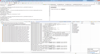
DMSC_Cortex_M3_0: GEL Output: This GEL is currently only supported for use from the Cortex-M3 inside the DMSC.
DMSC_Cortex_M3_0: GEL Output: Do not run this GEL from any other CPU on the SoC.
DMSC_Cortex_M3_0: GEL Output: This script sets the first address translation region to [0x8000_0000, 0x0000_0000].
DMSC_Cortex_M3_0: GEL Output: It also sets the second address translation region to    [0x6000_0000, 0x4000_0000].
DMSC_Cortex_M3_0: GEL Output: This is consistent with the SoC DV assumptions.
DMSC_Cortex_M3_0: GEL Output: Configuring ATCM for the R5Fs
DMSC_Cortex_M3_0: GEL Output: ATCM Configured.
DMSC_Cortex_M3_0: GEL Output: R5F Halt bits set.
DMSC_Cortex_M3_0: GEL Output: Configuring bootvectors
DMSC_Cortex_M3_0: GEL Output: Bootvectors configured.
DMSC_Cortex_M3_0: GEL Output: Debugging enabled
DMSC_Cortex_M3_0: GEL Output: Programming all PLLs.
DMSC_Cortex_M3_0: GEL Output: Programming Main PLL 0 (Main PLL)
DMSC_Cortex_M3_0: GEL Output: Unlocked PLL MMRs.
DMSC_Cortex_M3_0: GEL Output: Read configuration MMRs.
DMSC_Cortex_M3_0: GEL Output: temp value (HSDIV_Presence) = 0x000003FF
DMSC_Cortex_M3_0: GEL Output: HSDIV presence value = 0x000003FF
DMSC_Cortex_M3_0: GEL Output: Number of hsidvs: 10
DMSC_Cortex_M3_0: GEL Output: Parsed PLL configuration information.
DMSC_Cortex_M3_0: GEL Output: Note: deskew PLL programming isn't implemented yet
DMSC_Cortex_M3_0: GEL Output: This is a fractional PLL, continuing on with normal programming.
DMSC_Cortex_M3_0: GEL Output: For debugging:
DMSC_Cortex_M3_0: GEL Output: Base address: 0x00680000
DMSC_Cortex_M3_0: GEL Output: PLL index: 0x00000000
DMSC_Cortex_M3_0: GEL Output: PLL index register base: 0x00000000
DMSC_Cortex_M3_0: GEL Output: Register: 0x00000020
DMSC_Cortex_M3_0: GEL Output: Clocking scheme: 1
DMSC_Cortex_M3_0: GEL Output: Set PLL to external bypass via Control MMR.
DMSC_Cortex_M3_0: GEL Output: Disabled PLL
DMSC_Cortex_M3_0: GEL Output: Enabled noise-cancelling DAC.
DMSC_Cortex_M3_0: GEL Output: Enabled the Delta-Sigma modulator.
DMSC_Cortex_M3_0: GEL Output: Programmed Reference clock pre-divider in output clock divider register.
DMSC_Cortex_M3_0: GEL Output: Programmed the integer feedback divider value in Freq Control 0 register.
DMSC_Cortex_M3_0: GEL Output: Fractional Divider Value is -1, don't set the fractional divider.
DMSC_Cortex_M3_0: GEL Output: Programmed the fractional feedback divider in Freq Control 0 register.
DMSC_Cortex_M3_0: GEL Output: Disabled the 4-phase clock generator (clk_4ph_en) in the control register.
DMSC_Cortex_M3_0: GEL Output: Enabled the FOUT4PHASE clocks in the control register.
DMSC_Cortex_M3_0: GEL Output: Set the first post-divider value (POSTDIV1) in the output divider control register.
DMSC_Cortex_M3_0: GEL Output: Set the second post-divider value (POSTDIV2) in the output divider control register.
DMSC_Cortex_M3_0: GEL Output: Programming HSDIV #0
DMSC_Cortex_M3_0: GEL Output: hsdiv_value: 3
DMSC_Cortex_M3_0: GEL Output: HSDIV reset asserted
DMSC_Cortex_M3_0: GEL Output: HSDIV divider value programmed.
DMSC_Cortex_M3_0: GEL Output: HSDIV clock output enabled. Reset automatically de-asserted.
DMSC_Cortex_M3_0: GEL Output: HSDIV reset de-asserted
DMSC_Cortex_M3_0: GEL Output: HSDIV #0 programmed.
DMSC_Cortex_M3_0: GEL Output: Programming HSDIV #1
DMSC_Cortex_M3_0: GEL Output: hsdiv_value: 9
DMSC_Cortex_M3_0: GEL Output: HSDIV reset asserted
DMSC_Cortex_M3_0: GEL Output: HSDIV divider value programmed.
DMSC_Cortex_M3_0: GEL Output: HSDIV clock output enabled. Reset automatically de-asserted.
DMSC_Cortex_M3_0: GEL Output: HSDIV reset de-asserted
DMSC_Cortex_M3_0: GEL Output: HSDIV #1 programmed.
DMSC_Cortex_M3_0: GEL Output: Programming HSDIV #2
DMSC_Cortex_M3_0: GEL Output: hsdiv_value: 24
DMSC_Cortex_M3_0: GEL Output: HSDIV reset asserted
DMSC_Cortex_M3_0: GEL Output: HSDIV divider value programmed.
DMSC_Cortex_M3_0: GEL Output: HSDIV clock output enabled. Reset automatically de-asserted.
DMSC_Cortex_M3_0: GEL Output: HSDIV reset de-asserted
DMSC_Cortex_M3_0: GEL Output: HSDIV #2 programmed.
DMSC_Cortex_M3_0: GEL Output: Programming HSDIV #3
DMSC_Cortex_M3_0: GEL Output: hsdiv_value: 14
DMSC_Cortex_M3_0: GEL Output: HSDIV reset asserted
DMSC_Cortex_M3_0: GEL Output: HSDIV divider value programmed.
DMSC_Cortex_M3_0: GEL Output: HSDIV clock output enabled. Reset automatically de-asserted.
DMSC_Cortex_M3_0: GEL Output: HSDIV reset de-asserted
DMSC_Cortex_M3_0: GEL Output: HSDIV #3 programmed.
DMSC_Cortex_M3_0: GEL Output: Programming HSDIV #4
DMSC_Cortex_M3_0: GEL Output: hsdiv_value: 7
DMSC_Cortex_M3_0: GEL Output: HSDIV reset asserted
DMSC_Cortex_M3_0: GEL Output: HSDIV divider value programmed.
DMSC_Cortex_M3_0: GEL Output: HSDIV clock output enabled. Reset automatically de-asserted.
DMSC_Cortex_M3_0: GEL Output: HSDIV reset de-asserted
DMSC_Cortex_M3_0: GEL Output: HSDIV #4 programmed.
DMSC_Cortex_M3_0: GEL Output: Programming HSDIV #5
DMSC_Cortex_M3_0: GEL Output: hsdiv_value: 4
DMSC_Cortex_M3_0: GEL Output: HSDIV reset asserted
DMSC_Cortex_M3_0: GEL Output: HSDIV divider value programmed.
DMSC_Cortex_M3_0: GEL Output: HSDIV clock output enabled. Reset automatically de-asserted.
DMSC_Cortex_M3_0: GEL Output: HSDIV reset de-asserted
DMSC_Cortex_M3_0: GEL Output: HSDIV #5 programmed.
DMSC_Cortex_M3_0: GEL Output: Programming HSDIV #6
DMSC_Cortex_M3_0: GEL Output: hsdiv_value: 3
DMSC_Cortex_M3_0: GEL Output: HSDIV reset asserted
DMSC_Cortex_M3_0: GEL Output: HSDIV divider value programmed.
DMSC_Cortex_M3_0: GEL Output: HSDIV clock output enabled. Reset automatically de-asserted.
DMSC_Cortex_M3_0: GEL Output: HSDIV reset de-asserted
DMSC_Cortex_M3_0: GEL Output: HSDIV #6 programmed.
DMSC_Cortex_M3_0: GEL Output: Programming HSDIV #7
DMSC_Cortex_M3_0: GEL Output: hsdiv_value: 3
DMSC_Cortex_M3_0: GEL Output: HSDIV reset asserted
DMSC_Cortex_M3_0: GEL Output: HSDIV divider value programmed.
DMSC_Cortex_M3_0: GEL Output: HSDIV clock output enabled. Reset automatically de-asserted.
DMSC_Cortex_M3_0: GEL Output: HSDIV reset de-asserted
DMSC_Cortex_M3_0: GEL Output: HSDIV #7 programmed.
DMSC_Cortex_M3_0: GEL Output: Programming HSDIV #8
DMSC_Cortex_M3_0: GEL Output: hsdiv_value: 7
DMSC_Cortex_M3_0: GEL Output: HSDIV reset asserted
DMSC_Cortex_M3_0: GEL Output: HSDIV divider value programmed.
DMSC_Cortex_M3_0: GEL Output: HSDIV clock output enabled. Reset automatically de-asserted.
DMSC_Cortex_M3_0: GEL Output: HSDIV reset de-asserted
DMSC_Cortex_M3_0: GEL Output: HSDIV #8 programmed.
DMSC_Cortex_M3_0: GEL Output: Programming HSDIV #9
DMSC_Cortex_M3_0: GEL Output: hsdiv_value: 2
DMSC_Cortex_M3_0: GEL Output: HSDIV reset asserted
DMSC_Cortex_M3_0: GEL Output: HSDIV divider value programmed.
DMSC_Cortex_M3_0: GEL Output: HSDIV clock output enabled. Reset automatically de-asserted.
DMSC_Cortex_M3_0: GEL Output: HSDIV reset de-asserted
DMSC_Cortex_M3_0: GEL Output: HSDIV #9 programmed.
DMSC_Cortex_M3_0: GEL Output: Selected Main Domain PLL Controller.
DMSC_Cortex_M3_0: GEL Output: Cleared bit 0 in the PLL controller control register.
DMSC_Cortex_M3_0: GEL Output: Cleared bit 5 in the PLL Controller control register.
DMSC_Cortex_M3_0: GEL Output: PLL controller is now in bypass mode.
DMSC_Cortex_M3_0: GEL Output: Set reset isolation to prevent a warm reset from killing the PLL controller.
DMSC_Cortex_M3_0: GEL Output: Set PLLDIV1 (output_div1).
DMSC_Cortex_M3_0: GEL Output: addr: 0x80410124 = 0x00008000
DMSC_Cortex_M3_0: GEL Output: Clear GOSET.
DMSC_Cortex_M3_0: GEL Output: GOSTAT is clear.
DMSC_Cortex_M3_0: GEL Output: Set PLLDIV1 (output_div1).
DMSC_Cortex_M3_0: GEL Output: Set ALN1.
DMSC_Cortex_M3_0: GEL Output: addr: 0x80410104 = 0x00000012
DMSC_Cortex_M3_0: GEL Output: Set OCSEL to 0x12, point C on the observation clock input tree inside the PLL Controller.
DMSC_Cortex_M3_0: GEL Output: addr: 0x80410148 = 0x00000002
DMSC_Cortex_M3_0: GEL Output: Set the clock control register to enable the OBSCLK output (bit 1).
DMSC_Cortex_M3_0: GEL Output: Set GOSET to 1.
DMSC_Cortex_M3_0: GEL Output: GOSTAT is clear.
DMSC_Cortex_M3_0: GEL Output: Enable PLL Controller (write to bit 0 in control register).
DMSC_Cortex_M3_0: GEL Output: Set GOSET to 0.
DMSC_Cortex_M3_0: GEL Output: PLLCTRL reset is cleared. PLLCTRL is free.
DMSC_Cortex_M3_0: GEL Output: Set the enable bit in the control register.
DMSC_Cortex_M3_0: GEL Output: PLL is locked.
DMSC_Cortex_M3_0: GEL Output: External bypass is disabled '0'. PLL and HSDIV clocks are engaging the rest of the SoC.
DMSC_Cortex_M3_0: GEL Output: Main PLL 0 (Main PLL) Set.
DMSC_Cortex_M3_0: GEL Output: Programming Main PLL 1 (Peripheral 0 PLL)
DMSC_Cortex_M3_0: GEL Output: Unlocked PLL MMRs.
DMSC_Cortex_M3_0: GEL Output: Read configuration MMRs.
DMSC_Cortex_M3_0: GEL Output: temp value (HSDIV_Presence) = 0x0000007F
DMSC_Cortex_M3_0: GEL Output: HSDIV presence value = 0x0000007F
DMSC_Cortex_M3_0: GEL Output: Number of hsidvs: 7
DMSC_Cortex_M3_0: GEL Output: Parsed PLL configuration information.
DMSC_Cortex_M3_0: GEL Output: Note: deskew PLL programming isn't implemented yet
DMSC_Cortex_M3_0: GEL Output: This is a fractional PLL, continuing on with normal programming.
DMSC_Cortex_M3_0: GEL Output: For debugging:
DMSC_Cortex_M3_0: GEL Output: Base address: 0x00680000
DMSC_Cortex_M3_0: GEL Output: PLL index: 0x00000001
DMSC_Cortex_M3_0: GEL Output: PLL index register base: 0x00001000
DMSC_Cortex_M3_0: GEL Output: Register: 0x00000020
DMSC_Cortex_M3_0: GEL Output: Clocking scheme: 1
DMSC_Cortex_M3_0: GEL Output: Set PLL to external bypass via Control MMR.
DMSC_Cortex_M3_0: GEL Output: Disabled PLL
DMSC_Cortex_M3_0: GEL Output: Enabled noise-cancelling DAC.
DMSC_Cortex_M3_0: GEL Output: Enabled the Delta-Sigma modulator.
DMSC_Cortex_M3_0: GEL Output: Programmed Reference clock pre-divider in output clock divider register.
DMSC_Cortex_M3_0: GEL Output: Programmed the integer feedback divider value in Freq Control 0 register.
DMSC_Cortex_M3_0: GEL Output: Fractional Divider Value is -1, don't set the fractional divider.
DMSC_Cortex_M3_0: GEL Output: Programmed the fractional feedback divider in Freq Control 0 register.
DMSC_Cortex_M3_0: GEL Output: Disabled the 4-phase clock generator (clk_4ph_en) in the control register.
DMSC_Cortex_M3_0: GEL Output: Enabled the FOUT4PHASE clocks in the control register.
DMSC_Cortex_M3_0: GEL Output: Set the first post-divider value (POSTDIV1) in the output divider control register.
DMSC_Cortex_M3_0: GEL Output: Set the second post-divider value (POSTDIV2) in the output divider control register.
DMSC_Cortex_M3_0: GEL Output: Programming HSDIV #0
DMSC_Cortex_M3_0: GEL Output: hsdiv_value: 9
DMSC_Cortex_M3_0: GEL Output: HSDIV reset asserted
DMSC_Cortex_M3_0: GEL Output: HSDIV divider value programmed.
DMSC_Cortex_M3_0: GEL Output: HSDIV clock output enabled. Reset automatically de-asserted.
DMSC_Cortex_M3_0: GEL Output: HSDIV reset de-asserted
DMSC_Cortex_M3_0: GEL Output: HSDIV #0 programmed.
DMSC_Cortex_M3_0: GEL Output: Programming HSDIV #1
DMSC_Cortex_M3_0: GEL Output: hsdiv_value: 11
DMSC_Cortex_M3_0: GEL Output: HSDIV reset asserted
DMSC_Cortex_M3_0: GEL Output: HSDIV divider value programmed.
DMSC_Cortex_M3_0: GEL Output: HSDIV clock output enabled. Reset automatically de-asserted.
DMSC_Cortex_M3_0: GEL Output: HSDIV reset de-asserted
DMSC_Cortex_M3_0: GEL Output: HSDIV #1 programmed.
DMSC_Cortex_M3_0: GEL Output: Programming HSDIV #2
DMSC_Cortex_M3_0: GEL Output: hsdiv_value: 4
DMSC_Cortex_M3_0: GEL Output: HSDIV reset asserted
DMSC_Cortex_M3_0: GEL Output: HSDIV divider value programmed.
DMSC_Cortex_M3_0: GEL Output: HSDIV clock output enabled. Reset automatically de-asserted.
DMSC_Cortex_M3_0: GEL Output: HSDIV reset de-asserted
DMSC_Cortex_M3_0: GEL Output: HSDIV #2 programmed.
DMSC_Cortex_M3_0: GEL Output: Programming HSDIV #3
DMSC_Cortex_M3_0: GEL Output: hsdiv_value: 9
DMSC_Cortex_M3_0: GEL Output: HSDIV reset asserted
DMSC_Cortex_M3_0: GEL Output: HSDIV divider value programmed.
DMSC_Cortex_M3_0: GEL Output: HSDIV clock output enabled. Reset automatically de-asserted.
DMSC_Cortex_M3_0: GEL Output: HSDIV reset de-asserted
DMSC_Cortex_M3_0: GEL Output: HSDIV #3 programmed.
DMSC_Cortex_M3_0: GEL Output: Programming HSDIV #4
DMSC_Cortex_M3_0: GEL Output: hsdiv_value: 79
DMSC_Cortex_M3_0: GEL Output: HSDIV reset asserted
DMSC_Cortex_M3_0: GEL Output: HSDIV divider value programmed.
DMSC_Cortex_M3_0: GEL Output: HSDIV clock output enabled. Reset automatically de-asserted.
DMSC_Cortex_M3_0: GEL Output: HSDIV reset de-asserted
DMSC_Cortex_M3_0: GEL Output: HSDIV #4 programmed.
DMSC_Cortex_M3_0: GEL Output: Programming HSDIV #5
DMSC_Cortex_M3_0: GEL Output: hsdiv_value: 5
DMSC_Cortex_M3_0: GEL Output: HSDIV reset asserted
DMSC_Cortex_M3_0: GEL Output: HSDIV divider value programmed.
DMSC_Cortex_M3_0: GEL Output: HSDIV clock output enabled. Reset automatically de-asserted.
DMSC_Cortex_M3_0: GEL Output: HSDIV reset de-asserted
DMSC_Cortex_M3_0: GEL Output: HSDIV #5 programmed.
DMSC_Cortex_M3_0: GEL Output: Programming HSDIV #6
DMSC_Cortex_M3_0: GEL Output: hsdiv_value: 15
DMSC_Cortex_M3_0: GEL Output: HSDIV reset asserted
DMSC_Cortex_M3_0: GEL Output: HSDIV divider value programmed.
DMSC_Cortex_M3_0: GEL Output: HSDIV clock output enabled. Reset automatically de-asserted.
DMSC_Cortex_M3_0: GEL Output: HSDIV reset de-asserted
DMSC_Cortex_M3_0: GEL Output: HSDIV #6 programmed.
DMSC_Cortex_M3_0: GEL Output: Set the enable bit in the control register.
DMSC_Cortex_M3_0: GEL Output: PLL is locked.
DMSC_Cortex_M3_0: GEL Output: External bypass is disabled '0'. PLL and HSDIV clocks are engaging the rest of the SoC.
DMSC_Cortex_M3_0: GEL Output: Main PLL 1 (Peripheral 0 PLL) Set.
DMSC_Cortex_M3_0: GEL Output: Programming Main PLL 2 (Peripheral 1 PLL)
DMSC_Cortex_M3_0: GEL Output: Unlocked PLL MMRs.
DMSC_Cortex_M3_0: GEL Output: Read configuration MMRs.
DMSC_Cortex_M3_0: GEL Output: temp value (HSDIV_Presence) = 0x000003FF
DMSC_Cortex_M3_0: GEL Output: HSDIV presence value = 0x000003FF
DMSC_Cortex_M3_0: GEL Output: Number of hsidvs: 10
DMSC_Cortex_M3_0: GEL Output: Parsed PLL configuration information.
DMSC_Cortex_M3_0: GEL Output: Note: deskew PLL programming isn't implemented yet
DMSC_Cortex_M3_0: GEL Output: This is a fractional PLL, continuing on with normal programming.
DMSC_Cortex_M3_0: GEL Output: For debugging:
DMSC_Cortex_M3_0: GEL Output: Base address: 0x00680000
DMSC_Cortex_M3_0: GEL Output: PLL index: 0x00000002
DMSC_Cortex_M3_0: GEL Output: PLL index register base: 0x00002000
DMSC_Cortex_M3_0: GEL Output: Register: 0x00000020
DMSC_Cortex_M3_0: GEL Output: Clocking scheme: 1
DMSC_Cortex_M3_0: GEL Output: Set PLL to external bypass via Control MMR.
DMSC_Cortex_M3_0: GEL Output: Disabled PLL
DMSC_Cortex_M3_0: GEL Output: Enabled noise-cancelling DAC.
DMSC_Cortex_M3_0: GEL Output: Enabled the Delta-Sigma modulator.
DMSC_Cortex_M3_0: GEL Output: Programmed Reference clock pre-divider in output clock divider register.
DMSC_Cortex_M3_0: GEL Output: Programmed the integer feedback divider value in Freq Control 0 register.
DMSC_Cortex_M3_0: GEL Output: Fractional Divider Value is -1, don't set the fractional divider.
DMSC_Cortex_M3_0: GEL Output: Programmed the fractional feedback divider in Freq Control 0 register.
DMSC_Cortex_M3_0: GEL Output: Disabled the 4-phase clock generator (clk_4ph_en) in the control register.
DMSC_Cortex_M3_0: GEL Output: Enabled the FOUT4PHASE clocks in the control register.
DMSC_Cortex_M3_0: GEL Output: Set the first post-divider value (POSTDIV1) in the output divider control register.
DMSC_Cortex_M3_0: GEL Output: Set the second post-divider value (POSTDIV2) in the output divider control register.
DMSC_Cortex_M3_0: GEL Output: Programming HSDIV #0
DMSC_Cortex_M3_0: GEL Output: hsdiv_value: 5
DMSC_Cortex_M3_0: GEL Output: HSDIV reset asserted
DMSC_Cortex_M3_0: GEL Output: HSDIV divider value programmed.
DMSC_Cortex_M3_0: GEL Output: HSDIV clock output enabled. Reset automatically de-asserted.
DMSC_Cortex_M3_0: GEL Output: HSDIV reset de-asserted
DMSC_Cortex_M3_0: GEL Output: HSDIV #0 programmed.
DMSC_Cortex_M3_0: GEL Output: Programming HSDIV #1
DMSC_Cortex_M3_0: GEL Output: i: 1, HSDIV value is -1, don't program this one
DMSC_Cortex_M3_0: GEL Output: HSDIV clock output disabled.
DMSC_Cortex_M3_0: GEL Output: HSDIV #1 programmed.
DMSC_Cortex_M3_0: GEL Output: Programming HSDIV #2
DMSC_Cortex_M3_0: GEL Output: hsdiv_value: 8
DMSC_Cortex_M3_0: GEL Output: HSDIV reset asserted
DMSC_Cortex_M3_0: GEL Output: HSDIV divider value programmed.
DMSC_Cortex_M3_0: GEL Output: HSDIV clock output enabled. Reset automatically de-asserted.
DMSC_Cortex_M3_0: GEL Output: HSDIV reset de-asserted
DMSC_Cortex_M3_0: GEL Output: HSDIV #2 programmed.
DMSC_Cortex_M3_0: GEL Output: Programming HSDIV #3
DMSC_Cortex_M3_0: GEL Output: hsdiv_value: 5
DMSC_Cortex_M3_0: GEL Output: HSDIV reset asserted
DMSC_Cortex_M3_0: GEL Output: HSDIV divider value programmed.
DMSC_Cortex_M3_0: GEL Output: HSDIV clock output enabled. Reset automatically de-asserted.
DMSC_Cortex_M3_0: GEL Output: HSDIV reset de-asserted
DMSC_Cortex_M3_0: GEL Output: HSDIV #3 programmed.
DMSC_Cortex_M3_0: GEL Output: Programming HSDIV #4
DMSC_Cortex_M3_0: GEL Output: hsdiv_value: 17
DMSC_Cortex_M3_0: GEL Output: HSDIV reset asserted
DMSC_Cortex_M3_0: GEL Output: HSDIV divider value programmed.
DMSC_Cortex_M3_0: GEL Output: HSDIV clock output enabled. Reset automatically de-asserted.
DMSC_Cortex_M3_0: GEL Output: HSDIV reset de-asserted
DMSC_Cortex_M3_0: GEL Output: HSDIV #4 programmed.
DMSC_Cortex_M3_0: GEL Output: Programming HSDIV #5
DMSC_Cortex_M3_0: GEL Output: hsdiv_value: 7
DMSC_Cortex_M3_0: GEL Output: HSDIV reset asserted
DMSC_Cortex_M3_0: GEL Output: HSDIV divider value programmed.
DMSC_Cortex_M3_0: GEL Output: HSDIV clock output enabled. Reset automatically de-asserted.
DMSC_Cortex_M3_0: GEL Output: HSDIV reset de-asserted
DMSC_Cortex_M3_0: GEL Output: HSDIV #5 programmed.
DMSC_Cortex_M3_0: GEL Output: Programming HSDIV #6
DMSC_Cortex_M3_0: GEL Output: hsdiv_value: 7
DMSC_Cortex_M3_0: GEL Output: HSDIV reset asserted
DMSC_Cortex_M3_0: GEL Output: HSDIV divider value programmed.
DMSC_Cortex_M3_0: GEL Output: HSDIV clock output enabled. Reset automatically de-asserted.
DMSC_Cortex_M3_0: GEL Output: HSDIV reset de-asserted
DMSC_Cortex_M3_0: GEL Output: HSDIV #6 programmed.
DMSC_Cortex_M3_0: GEL Output: Programming HSDIV #7
DMSC_Cortex_M3_0: GEL Output: hsdiv_value: 17
DMSC_Cortex_M3_0: GEL Output: HSDIV reset asserted
DMSC_Cortex_M3_0: GEL Output: HSDIV divider value programmed.
DMSC_Cortex_M3_0: GEL Output: HSDIV clock output enabled. Reset automatically de-asserted.
DMSC_Cortex_M3_0: GEL Output: HSDIV reset de-asserted
DMSC_Cortex_M3_0: GEL Output: HSDIV #7 programmed.
DMSC_Cortex_M3_0: GEL Output: Programming HSDIV #8
DMSC_Cortex_M3_0: GEL Output: i: 8, HSDIV value is -1, don't program this one
DMSC_Cortex_M3_0: GEL Output: HSDIV clock output disabled.
DMSC_Cortex_M3_0: GEL Output: HSDIV #8 programmed.
DMSC_Cortex_M3_0: GEL Output: Programming HSDIV #9
DMSC_Cortex_M3_0: GEL Output: hsdiv_value: 4
DMSC_Cortex_M3_0: GEL Output: HSDIV reset asserted
DMSC_Cortex_M3_0: GEL Output: HSDIV divider value programmed.
DMSC_Cortex_M3_0: GEL Output: HSDIV clock output enabled. Reset automatically de-asserted.
DMSC_Cortex_M3_0: GEL Output: HSDIV reset de-asserted
DMSC_Cortex_M3_0: GEL Output: HSDIV #9 programmed.
DMSC_Cortex_M3_0: GEL Output: Set the enable bit in the control register.
DMSC_Cortex_M3_0: GEL Output: PLL is locked.
DMSC_Cortex_M3_0: GEL Output: External bypass is disabled '0'. PLL and HSDIV clocks are engaging the rest of the SoC.
DMSC_Cortex_M3_0: GEL Output: Main PLL 2 (Peripheral 1 PLL) Set.
DMSC_Cortex_M3_0: GEL Output: Programming Main PLL 8 (ARM0 PLL)
DMSC_Cortex_M3_0: GEL Output: Unlocked PLL MMRs.
DMSC_Cortex_M3_0: GEL Output: Read configuration MMRs.
DMSC_Cortex_M3_0: GEL Output: temp value (HSDIV_Presence) = 0x00000001
DMSC_Cortex_M3_0: GEL Output: HSDIV presence value = 0x00000001
DMSC_Cortex_M3_0: GEL Output: Number of hsidvs: 1
DMSC_Cortex_M3_0: GEL Output: Parsed PLL configuration information.
DMSC_Cortex_M3_0: GEL Output: Note: deskew PLL programming isn't implemented yet
DMSC_Cortex_M3_0: GEL Output: This is a fractional PLL, continuing on with normal programming.
DMSC_Cortex_M3_0: GEL Output: For debugging:
DMSC_Cortex_M3_0: GEL Output: Base address: 0x00680000
DMSC_Cortex_M3_0: GEL Output: PLL index: 0x00000008
DMSC_Cortex_M3_0: GEL Output: PLL index register base: 0x00008000
DMSC_Cortex_M3_0: GEL Output: Register: 0x00000020
DMSC_Cortex_M3_0: GEL Output: Clocking scheme: 1
DMSC_Cortex_M3_0: GEL Output: Set PLL to external bypass via Control MMR.
DMSC_Cortex_M3_0: GEL Output: Disabled PLL
DMSC_Cortex_M3_0: GEL Output: Enabled noise-cancelling DAC.
DMSC_Cortex_M3_0: GEL Output: Enabled the Delta-Sigma modulator.
DMSC_Cortex_M3_0: GEL Output: Programmed Reference clock pre-divider in output clock divider register.
DMSC_Cortex_M3_0: GEL Output: Programmed the integer feedback divider value in Freq Control 0 register.
DMSC_Cortex_M3_0: GEL Output: Fractional Divider Value is -1, don't set the fractional divider.
DMSC_Cortex_M3_0: GEL Output: Programmed the fractional feedback divider in Freq Control 0 register.
DMSC_Cortex_M3_0: GEL Output: Disabled the 4-phase clock generator (clk_4ph_en) in the control register.
DMSC_Cortex_M3_0: GEL Output: Enabled the FOUT4PHASE clocks in the control register.
DMSC_Cortex_M3_0: GEL Output: Set the first post-divider value (POSTDIV1) in the output divider control register.
DMSC_Cortex_M3_0: GEL Output: Set the second post-divider value (POSTDIV2) in the output divider control register.
DMSC_Cortex_M3_0: GEL Output: Programming HSDIV #0
DMSC_Cortex_M3_0: GEL Output: hsdiv_value: 1
DMSC_Cortex_M3_0: GEL Output: HSDIV reset asserted
DMSC_Cortex_M3_0: GEL Output: HSDIV divider value programmed.
DMSC_Cortex_M3_0: GEL Output: HSDIV clock output enabled. Reset automatically de-asserted.
DMSC_Cortex_M3_0: GEL Output: HSDIV reset de-asserted
DMSC_Cortex_M3_0: GEL Output: HSDIV #0 programmed.
DMSC_Cortex_M3_0: GEL Output: Set the enable bit in the control register.
DMSC_Cortex_M3_0: GEL Output: PLL is locked.
DMSC_Cortex_M3_0: GEL Output: External bypass is disabled '0'. PLL and HSDIV clocks are engaging the rest of the SoC.
DMSC_Cortex_M3_0: GEL Output: Main PLL 8 (ARM0 PLL) Set.
DMSC_Cortex_M3_0: GEL Output: Programming Main PLL 12 (DDR PLL)
DMSC_Cortex_M3_0: GEL Output: Unlocked PLL MMRs.
DMSC_Cortex_M3_0: GEL Output: Read configuration MMRs.
DMSC_Cortex_M3_0: GEL Output: temp value (HSDIV_Presence) = 0x00000001
DMSC_Cortex_M3_0: GEL Output: HSDIV presence value = 0x00000001
DMSC_Cortex_M3_0: GEL Output: Number of hsidvs: 1
DMSC_Cortex_M3_0: GEL Output: Parsed PLL configuration information.
DMSC_Cortex_M3_0: GEL Output: Note: deskew PLL programming isn't implemented yet
DMSC_Cortex_M3_0: GEL Output: This is a fractional PLL, continuing on with normal programming.
DMSC_Cortex_M3_0: GEL Output: For debugging:
DMSC_Cortex_M3_0: GEL Output: Base address: 0x00680000
DMSC_Cortex_M3_0: GEL Output: PLL index: 0x0000000C
DMSC_Cortex_M3_0: GEL Output: PLL index register base: 0x0000C000
DMSC_Cortex_M3_0: GEL Output: Register: 0x00000020
DMSC_Cortex_M3_0: GEL Output: Clocking scheme: 1
DMSC_Cortex_M3_0: GEL Output: Set PLL to external bypass via Control MMR.
DMSC_Cortex_M3_0: GEL Output: Disabled PLL
DMSC_Cortex_M3_0: GEL Output: Enabled noise-cancelling DAC.
DMSC_Cortex_M3_0: GEL Output: Enabled the Delta-Sigma modulator.
DMSC_Cortex_M3_0: GEL Output: Programmed Reference clock pre-divider in output clock divider register.
DMSC_Cortex_M3_0: GEL Output: Programmed the integer feedback divider value in Freq Control 0 register.
DMSC_Cortex_M3_0: GEL Output: Fractional Divider Value is -1, don't set the fractional divider.
DMSC_Cortex_M3_0: GEL Output: Programmed the fractional feedback divider in Freq Control 0 register.
DMSC_Cortex_M3_0: GEL Output: Disabled the 4-phase clock generator (clk_4ph_en) in the control register.
DMSC_Cortex_M3_0: GEL Output: Enabled the FOUT4PHASE clocks in the control register.
DMSC_Cortex_M3_0: GEL Output: Set the first post-divider value (POSTDIV1) in the output divider control register.
DMSC_Cortex_M3_0: GEL Output: Set the second post-divider value (POSTDIV2) in the output divider control register.
DMSC_Cortex_M3_0: GEL Output: Programming HSDIV #0
DMSC_Cortex_M3_0: GEL Output: hsdiv_value: 3
DMSC_Cortex_M3_0: GEL Output: HSDIV reset asserted
DMSC_Cortex_M3_0: GEL Output: HSDIV divider value programmed.
DMSC_Cortex_M3_0: GEL Output: HSDIV clock output enabled. Reset automatically de-asserted.
DMSC_Cortex_M3_0: GEL Output: HSDIV reset de-asserted
DMSC_Cortex_M3_0: GEL Output: HSDIV #0 programmed.
DMSC_Cortex_M3_0: GEL Output: Set the enable bit in the control register.
DMSC_Cortex_M3_0: GEL Output: PLL is locked.
DMSC_Cortex_M3_0: GEL Output: External bypass is disabled '0'. PLL and HSDIV clocks are engaging the rest of the SoC.
DMSC_Cortex_M3_0: GEL Output: Main PLL 12 (DDR PLL) Set.
DMSC_Cortex_M3_0: GEL Output: Programming Main PLL 14 (Main Domain Pulsar) PLL)
DMSC_Cortex_M3_0: GEL Output: Unlocked PLL MMRs.
DMSC_Cortex_M3_0: GEL Output: Read configuration MMRs.
DMSC_Cortex_M3_0: GEL Output: temp value (HSDIV_Presence) = 0x00000003
DMSC_Cortex_M3_0: GEL Output: HSDIV presence value = 0x00000003
DMSC_Cortex_M3_0: GEL Output: Number of hsidvs: 2
DMSC_Cortex_M3_0: GEL Output: Parsed PLL configuration information.
DMSC_Cortex_M3_0: GEL Output: Note: deskew PLL programming isn't implemented yet
DMSC_Cortex_M3_0: GEL Output: This is a fractional PLL, continuing on with normal programming.
DMSC_Cortex_M3_0: GEL Output: For debugging:
DMSC_Cortex_M3_0: GEL Output: Base address: 0x00680000
DMSC_Cortex_M3_0: GEL Output: PLL index: 0x0000000E
DMSC_Cortex_M3_0: GEL Output: PLL index register base: 0x0000E000
DMSC_Cortex_M3_0: GEL Output: Register: 0x00000020
DMSC_Cortex_M3_0: GEL Output: Clocking scheme: 1
DMSC_Cortex_M3_0: GEL Output: Set PLL to external bypass via Control MMR.
DMSC_Cortex_M3_0: GEL Output: Disabled PLL
DMSC_Cortex_M3_0: GEL Output: Enabled noise-cancelling DAC.
DMSC_Cortex_M3_0: GEL Output: Enabled the Delta-Sigma modulator.
DMSC_Cortex_M3_0: GEL Output: Programmed Reference clock pre-divider in output clock divider register.
DMSC_Cortex_M3_0: GEL Output: Programmed the integer feedback divider value in Freq Control 0 register.
DMSC_Cortex_M3_0: GEL Output: Fractional Divider Value is -1, don't set the fractional divider.
DMSC_Cortex_M3_0: GEL Output: Programmed the fractional feedback divider in Freq Control 0 register.
DMSC_Cortex_M3_0: GEL Output: Disabled the 4-phase clock generator (clk_4ph_en) in the control register.
DMSC_Cortex_M3_0: GEL Output: Enabled the FOUT4PHASE clocks in the control register.
DMSC_Cortex_M3_0: GEL Output: Set the first post-divider value (POSTDIV1) in the output divider control register.
DMSC_Cortex_M3_0: GEL Output: Set the second post-divider value (POSTDIV2) in the output divider control register.
DMSC_Cortex_M3_0: GEL Output: Programming HSDIV #0
DMSC_Cortex_M3_0: GEL Output: hsdiv_value: 2
DMSC_Cortex_M3_0: GEL Output: HSDIV reset asserted
DMSC_Cortex_M3_0: GEL Output: HSDIV divider value programmed.
DMSC_Cortex_M3_0: GEL Output: HSDIV clock output enabled. Reset automatically de-asserted.
DMSC_Cortex_M3_0: GEL Output: HSDIV reset de-asserted
DMSC_Cortex_M3_0: GEL Output: HSDIV #0 programmed.
DMSC_Cortex_M3_0: GEL Output: Programming HSDIV #1
DMSC_Cortex_M3_0: GEL Output: hsdiv_value: 2
DMSC_Cortex_M3_0: GEL Output: HSDIV reset asserted
DMSC_Cortex_M3_0: GEL Output: HSDIV divider value programmed.
DMSC_Cortex_M3_0: GEL Output: HSDIV clock output enabled. Reset automatically de-asserted.
DMSC_Cortex_M3_0: GEL Output: HSDIV reset de-asserted
DMSC_Cortex_M3_0: GEL Output: HSDIV #1 programmed.
DMSC_Cortex_M3_0: GEL Output: Set the enable bit in the control register.
DMSC_Cortex_M3_0: GEL Output: PLL is locked.
DMSC_Cortex_M3_0: GEL Output: External bypass is disabled '0'. PLL and HSDIV clocks are engaging the rest of the SoC.
DMSC_Cortex_M3_0: GEL Output: Main PLL 14 (Main Domain Pulsar PLL) Set.
DMSC_Cortex_M3_0: GEL Output: Programming MCU PLL 0 (MCU PLL)
DMSC_Cortex_M3_0: GEL Output: Unlocked PLL MMRs.
DMSC_Cortex_M3_0: GEL Output: Read configuration MMRs.
DMSC_Cortex_M3_0: GEL Output: temp value (HSDIV_Presence) = 0x0000001F
DMSC_Cortex_M3_0: GEL Output: HSDIV presence value = 0x0000001F
DMSC_Cortex_M3_0: GEL Output: Number of hsidvs: 5
DMSC_Cortex_M3_0: GEL Output: Parsed PLL configuration information.
DMSC_Cortex_M3_0: GEL Output: Note: deskew PLL programming isn't implemented yet
DMSC_Cortex_M3_0: GEL Output: This is a fractional PLL, continuing on with normal programming.
DMSC_Cortex_M3_0: GEL Output: For debugging:
DMSC_Cortex_M3_0: GEL Output: Base address: 0x04040000
DMSC_Cortex_M3_0: GEL Output: PLL index: 0x00000000
DMSC_Cortex_M3_0: GEL Output: PLL index register base: 0x00000000
DMSC_Cortex_M3_0: GEL Output: Register: 0x00000020
DMSC_Cortex_M3_0: GEL Output: Clocking scheme: 1
DMSC_Cortex_M3_0: GEL Output: Set PLL to external bypass via Control MMR.
DMSC_Cortex_M3_0: GEL Output: Disabled PLL
DMSC_Cortex_M3_0: GEL Output: Enabled noise-cancelling DAC.
DMSC_Cortex_M3_0: GEL Output: Enabled the Delta-Sigma modulator.
DMSC_Cortex_M3_0: GEL Output: Programmed Reference clock pre-divider in output clock divider register.
DMSC_Cortex_M3_0: GEL Output: Programmed the integer feedback divider value in Freq Control 0 register.
DMSC_Cortex_M3_0: GEL Output: Fractional Divider Value is -1, don't set the fractional divider.
DMSC_Cortex_M3_0: GEL Output: Programmed the fractional feedback divider in Freq Control 0 register.
DMSC_Cortex_M3_0: GEL Output: Disabled the 4-phase clock generator (clk_4ph_en) in the control register.
DMSC_Cortex_M3_0: GEL Output: Enabled the FOUT4PHASE clocks in the control register.
DMSC_Cortex_M3_0: GEL Output: Set the first post-divider value (POSTDIV1) in the output divider control register.
DMSC_Cortex_M3_0: GEL Output: Set the second post-divider value (POSTDIV2) in the output divider control register.
DMSC_Cortex_M3_0: GEL Output: Programming HSDIV #0
DMSC_Cortex_M3_0: GEL Output: hsdiv_value: 5
DMSC_Cortex_M3_0: GEL Output: HSDIV reset asserted
DMSC_Cortex_M3_0: GEL Output: HSDIV divider value programmed.
DMSC_Cortex_M3_0: GEL Output: HSDIV clock output enabled. Reset automatically de-asserted.
DMSC_Cortex_M3_0: GEL Output: HSDIV reset de-asserted
DMSC_Cortex_M3_0: GEL Output: HSDIV #0 programmed.
DMSC_Cortex_M3_0: GEL Output: Programming HSDIV #1
DMSC_Cortex_M3_0: GEL Output: hsdiv_value: 24
DMSC_Cortex_M3_0: GEL Output: HSDIV reset asserted
DMSC_Cortex_M3_0: GEL Output: HSDIV divider value programmed.
DMSC_Cortex_M3_0: GEL Output: HSDIV clock output enabled. Reset automatically de-asserted.
DMSC_Cortex_M3_0: GEL Output: HSDIV reset de-asserted
DMSC_Cortex_M3_0: GEL Output: HSDIV #1 programmed.
DMSC_Cortex_M3_0: GEL Output: Programming HSDIV #2
DMSC_Cortex_M3_0: GEL Output: hsdiv_value: 24
DMSC_Cortex_M3_0: GEL Output: HSDIV reset asserted
DMSC_Cortex_M3_0: GEL Output: HSDIV divider value programmed.
DMSC_Cortex_M3_0: GEL Output: HSDIV clock output enabled. Reset automatically de-asserted.
DMSC_Cortex_M3_0: GEL Output: HSDIV reset de-asserted
DMSC_Cortex_M3_0: GEL Output: HSDIV #2 programmed.
DMSC_Cortex_M3_0: GEL Output: Programming HSDIV #3
DMSC_Cortex_M3_0: GEL Output: hsdiv_value: 11
DMSC_Cortex_M3_0: GEL Output: HSDIV reset asserted
DMSC_Cortex_M3_0: GEL Output: HSDIV divider value programmed.
DMSC_Cortex_M3_0: GEL Output: HSDIV clock output enabled. Reset automatically de-asserted.
DMSC_Cortex_M3_0: GEL Output: HSDIV reset de-asserted
DMSC_Cortex_M3_0: GEL Output: HSDIV #3 programmed.
DMSC_Cortex_M3_0: GEL Output: Programming HSDIV #4
DMSC_Cortex_M3_0: GEL Output: hsdiv_value: 11
DMSC_Cortex_M3_0: GEL Output: HSDIV reset asserted
DMSC_Cortex_M3_0: GEL Output: HSDIV divider value programmed.
DMSC_Cortex_M3_0: GEL Output: HSDIV clock output enabled. Reset automatically de-asserted.
DMSC_Cortex_M3_0: GEL Output: HSDIV reset de-asserted
DMSC_Cortex_M3_0: GEL Output: HSDIV #4 programmed.
DMSC_Cortex_M3_0: GEL Output: Selected MCU Domain PLL Conntroller.
DMSC_Cortex_M3_0: GEL Output: Cleared bit 0 in the PLL controller control register.
DMSC_Cortex_M3_0: GEL Output: Cleared bit 5 in the PLL Controller control register.
DMSC_Cortex_M3_0: GEL Output: PLL controller is now in bypass mode.
DMSC_Cortex_M3_0: GEL Output: Set reset isolation to prevent a warm reset from killing the PLL controller.
DMSC_Cortex_M3_0: GEL Output: Set PLLDIV1 (output_div1).
DMSC_Cortex_M3_0: GEL Output: addr: 0x84020124 = 0x00008000
DMSC_Cortex_M3_0: GEL Output: Clear GOSET.
DMSC_Cortex_M3_0: GEL Output: GOSTAT is clear.
DMSC_Cortex_M3_0: GEL Output: Set PLLDIV1 (output_div1).
DMSC_Cortex_M3_0: GEL Output: Set ALN1.
DMSC_Cortex_M3_0: GEL Output: addr: 0x84020104 = 0x00000012
DMSC_Cortex_M3_0: GEL Output: Set OCSEL to 0x12, point C on the observation clock input tree inside the PLL Controller.
DMSC_Cortex_M3_0: GEL Output: addr: 0x84020148 = 0x00000002
DMSC_Cortex_M3_0: GEL Output: Set the clock control register to enable the OBSCLK output (bit 1).
DMSC_Cortex_M3_0: GEL Output: Set GOSET to 1.
DMSC_Cortex_M3_0: GEL Output: GOSTAT is clear.
DMSC_Cortex_M3_0: GEL Output: Enable PLL Controller (write to bit 0 in control register).
DMSC_Cortex_M3_0: GEL Output: Set GOSET to 0.
DMSC_Cortex_M3_0: GEL Output: PLLCTRL reset is cleared. PLLCTRL is free.
DMSC_Cortex_M3_0: GEL Output: Set the enable bit in the control register.
DMSC_Cortex_M3_0: GEL Output: PLL is locked.
DMSC_Cortex_M3_0: GEL Output: External bypass is disabled '0'. PLL and HSDIV clocks are engaging the rest of the SoC.
DMSC_Cortex_M3_0: GEL Output: MCU PLL 0 (MCU PLL) Set.
DMSC_Cortex_M3_0: GEL Output: All PLLs programmed.
DMSC_Cortex_M3_0: GEL Output: Powering up all PSC power domains in progress...
DMSC_Cortex_M3_0: GEL Output: Powering up MAIN domain peripherals...
DMSC_Cortex_M3_0: GEL Output: Powering up GP_CORE_CTL.
DMSC_Cortex_M3_0: GEL Output: Powering up LPSC_DMSC
DMSC_Cortex_M3_0: GEL Output: No change needed.
DMSC_Cortex_M3_0: GEL Output: Powering up LPSC_MAIN_TEST
DMSC_Cortex_M3_0: GEL Output: No change needed.
DMSC_Cortex_M3_0: GEL Output: Powering up LPSC_MAIN_PBIST
DMSC_Cortex_M3_0: GEL Output: No change needed.
DMSC_Cortex_M3_0: GEL Output: Powering up LPSC_EMMC_4B
DMSC_Cortex_M3_0: GEL Output: Power domain and module state changed successfully.
DMSC_Cortex_M3_0: GEL Output: Powering up LPSC_EMMC_8B
DMSC_Cortex_M3_0: GEL Output: Power domain and module state changed successfully.
DMSC_Cortex_M3_0: GEL Output: Powering up LPSC_USB
DMSC_Cortex_M3_0: GEL Output: Power domain and module state changed successfully.
DMSC_Cortex_M3_0: GEL Output: Powering up LPSC_ADC
DMSC_Cortex_M3_0: GEL Output: Power domain and module state changed successfully.
DMSC_Cortex_M3_0: GEL Output: Powering up LPSC_DEBUGSS
DMSC_Cortex_M3_0: GEL Output: No change needed.
DMSC_Cortex_M3_0: GEL Output: Powering up LPSC_GPMC
DMSC_Cortex_M3_0: GEL Output: Power domain and module state changed successfully.
DMSC_Cortex_M3_0: GEL Output: Powering up LPSC_EMIF_CFG
DMSC_Cortex_M3_0: GEL Output: Power domain and module state changed successfully.
DMSC_Cortex_M3_0: GEL Output: Powering up LPSC_EMIF_DATA
DMSC_Cortex_M3_0: GEL Output: Power domain and module state changed successfully.
DMSC_Cortex_M3_0: GEL Output: Powering up LPSC_MCAN_0
DMSC_Cortex_M3_0: GEL Output: Power domain and module state changed successfully.
DMSC_Cortex_M3_0: GEL Output: Powering up LPSC_MCAN_1
DMSC_Cortex_M3_0: GEL Output: Power domain and module state changed successfully.
DMSC_Cortex_M3_0: GEL Output: Powering up LPSC_SA2UL
DMSC_Cortex_M3_0: GEL Output: No change needed.
DMSC_Cortex_M3_0: GEL Output: Powering up LPSC_SERDES_0
DMSC_Cortex_M3_0: GEL Output: Power domain and module state changed successfully.
DMSC_Cortex_M3_0: GEL Output: Powering up LPSC_PCIE_0
DMSC_Cortex_M3_0: GEL Output: Power domain and module state changed successfully.
DMSC_Cortex_M3_0: GEL Output: Powering up GP_CORE_CTL done.
DMSC_Cortex_M3_0: GEL Output: Powering up PD_A53_CLUSTER_0.
DMSC_Cortex_M3_0: GEL Output: Powering up LPSC_A53_CLUSTER_0
DMSC_Cortex_M3_0: GEL Output: ERROR: module state NOT changed!
DMSC_Cortex_M3_0: GEL Output: Powering up LPSC_A53_CLUSTER_0_PBIST
DMSC_Cortex_M3_0: GEL Output: Power domain and module state changed successfully.
DMSC_Cortex_M3_0: GEL Output: Powering up PD_A53_CLUSTER_0 done.
DMSC_Cortex_M3_0: GEL Output: Powering up PD_A53_0.
DMSC_Cortex_M3_0: GEL Output: Powering up LPSC_A53_0
DMSC_Cortex_M3_0: GEL Output: ERROR: module state NOT changed!
DMSC_Cortex_M3_0: GEL Output: Powering up PD_A53_0 done.
DMSC_Cortex_M3_0: GEL Output: Powering up PD_A53_1.
DMSC_Cortex_M3_0: GEL Output: Powering up LPSC_A53_1
DMSC_Cortex_M3_0: GEL Output: ERROR: module state NOT changed!
DMSC_Cortex_M3_0: GEL Output: Powering up PD_A53_1 done.
DMSC_Cortex_M3_0: GEL Output: Powering up PD_PULSAR_0.
DMSC_Cortex_M3_0: GEL Output: Powering up LPSC_PULSAR_0_R5_0
DMSC_Cortex_M3_0: GEL Output: No change needed.
DMSC_Cortex_M3_0: GEL Output: Powering up LPSC_PULSAR_0_R5_1
DMSC_Cortex_M3_0: GEL Output: Power domain and module state changed successfully.
DMSC_Cortex_M3_0: GEL Output: Powering up LPSC_PULSAR_PBIST_0
DMSC_Cortex_M3_0: GEL Output: Power domain and module state changed successfully.
DMSC_Cortex_M3_0: GEL Output: Powering up PD_PULSAR_0 done.
DMSC_Cortex_M3_0: GEL Output: Powering up PD_PULSAR_1.
DMSC_Cortex_M3_0: GEL Output: Powering up LPSC_PULSAR_1_R5_0
DMSC_Cortex_M3_0: GEL Output: Power domain and module state changed successfully.
DMSC_Cortex_M3_0: GEL Output: Powering up LPSC_PULSAR_1_R5_1
DMSC_Cortex_M3_0: GEL Output: Power domain and module state changed successfully.
DMSC_Cortex_M3_0: GEL Output: Powering up LPSC_PULSAR_PBIST_1
DMSC_Cortex_M3_0: GEL Output: Power domain and module state changed successfully.
DMSC_Cortex_M3_0: GEL Output: Powering up PD_PULSAR_1 done.
DMSC_Cortex_M3_0: GEL Output: Powering up PD_ICSSG_0.
DMSC_Cortex_M3_0: GEL Output: Powering up LPSC_ICSSG_0
DMSC_Cortex_M3_0: GEL Output: Power domain and module state changed successfully.
DMSC_Cortex_M3_0: GEL Output: Powering up PD_ICSSG_0 done.
DMSC_Cortex_M3_0: GEL Output: Powering up PD_ICSSG_1.
DMSC_Cortex_M3_0: GEL Output: Powering up LPSC_ICSSG_1
DMSC_Cortex_M3_0: GEL Output: Power domain and module state changed successfully.
DMSC_Cortex_M3_0: GEL Output: Powering up PD_ICSSG_1 done.
DMSC_Cortex_M3_0: GEL Output: Powering up PD_CPSW.
DMSC_Cortex_M3_0: GEL Output: Powering up LPSC_CPSW3G
DMSC_Cortex_M3_0: GEL Output: Power domain and module state changed successfully.
DMSC_Cortex_M3_0: GEL Output: Powering up PD_CPSW done.
DMSC_Cortex_M3_0: GEL Output: Powering up all MAIN domain peripherals done.
DMSC_Cortex_M3_0: GEL Output: Powering up MCU Domain peripherals.
DMSC_Cortex_M3_0: GEL Output: Powering up GP_CORE_CTL_MCU.
DMSC_Cortex_M3_0: GEL Output: Powering up LPSC_TEST
DMSC_Cortex_M3_0: GEL Output: No change needed.
DMSC_Cortex_M3_0: GEL Output: Powering up LPSC_MAIN2MCU
DMSC_Cortex_M3_0: GEL Output: No change needed.
DMSC_Cortex_M3_0: GEL Output: Powering up LPSC_MCU2MAIN
DMSC_Cortex_M3_0: GEL Output: No change needed.
DMSC_Cortex_M3_0: GEL Output: Powering up GP_CORE_CTL_MCU done.
DMSC_Cortex_M3_0: GEL Output: Powering up PD_M4F.
DMSC_Cortex_M3_0: GEL Output: Powering up LPSC_M4F
DMSC_Cortex_M3_0: GEL Output: Power domain and module state changed successfully.
DMSC_Cortex_M3_0: GEL Output: Powering up PD_M4F done.
DMSC_Cortex_M3_0: GEL Output: Powering up MCU Domain peripherals done.
DMSC_Cortex_M3_0: GEL Output: Powering up all PSC power domains done!
DMSC_Cortex_M3_0: GEL Output:
DMSC_Cortex_M3_0: GEL Output: *****DDR is configured using R5 or A53 GELs
DMSC_Cortex_M3_0: GEL Output: M4F WFI Vector set into IRAM.
MAIN_Cortex_R5_0_0: GEL Output: Running from R5
MAIN_Cortex_R5_0_0: GEL Output:

DDR not initialized with R5 connect.

Go to menu Scripts --> AM64 DDR Initialization -> AM64_DDR_Initialization_ECC_Disabled to initialize DDR.

====

MAIN_Cortex_R5_0_0: GEL Output: --->>> DDR4 Initialization is in progress ... <<<---
MAIN_Cortex_R5_0_0: GEL Output: --->>> ECC Enabled <<<---
MAIN_Cortex_R5_0_0: GEL Output: --->>> After priming ECC memory, enable ECC_CK bit with hotmenu AM64 DDR Memory config --> Enable_TI_InlineECC_CK_During_Reads()<<<---
MAIN_Cortex_R5_0_0: GEL Output: --->>> DDR controller programming in progress.. <<<---
MAIN_Cortex_R5_0_0: GEL Output: --->>> DDR controller programming completed... <<<---
MAIN_Cortex_R5_0_0: GEL Output: --->>> DDR PI programming in progress.. <<<---
MAIN_Cortex_R5_0_0: GEL Output: --->>> DDR PI programming completed... <<<---
MAIN_Cortex_R5_0_0: GEL Output: --->>> DDR PHY Data Slice 0 programming in progress.. <<<---
MAIN_Cortex_R5_0_0: GEL Output: --->>> DDR PHY Data Slice 0 programming completed... <<<---
MAIN_Cortex_R5_0_0: GEL Output: --->>> DDR PHY Data Slice 1 programming in progress.. <<<---
MAIN_Cortex_R5_0_0: GEL Output: --->>> DDR PHY Data Slice 1 programming completed... <<<---
MAIN_Cortex_R5_0_0: GEL Output: --->>> DDR PHY Address Slice 0 programming in progress.. <<<---
MAIN_Cortex_R5_0_0: GEL Output: --->>> DDR PHY Data Slice 2 programming completed... <<<---
MAIN_Cortex_R5_0_0: GEL Output: --->>> DDR PHY Address Slice 1 programming in progress.. <<<---
MAIN_Cortex_R5_0_0: GEL Output: --->>> DDR PHY Address Slice 1 programming completed... <<<---
MAIN_Cortex_R5_0_0: GEL Output: --->>> DDR PHY Address slice 2 programming in progress.. <<<---
MAIN_Cortex_R5_0_0: GEL Output: --->>> DDR PHY Address Slice 2 programming completed... <<<---
MAIN_Cortex_R5_0_0: GEL Output: --->>> DDR PHY programming in progress.. <<<---
MAIN_Cortex_R5_0_0: GEL Output: --->>> Set PHY registers for all FSPs simultaneously (multicast)... <<<---
MAIN_Cortex_R5_0_0: GEL Output: --->>> DDR PHY programming completed... <<<---
MAIN_Cortex_R5_0_0: GEL Output: Debugging enabled
MAIN_Cortex_R5_0_0: GEL Output: Setting MAIN_PLL12_HSDIV0_CLKOUT_400MHz
MAIN_Cortex_R5_0_0: GEL Output: hsdiv_value: 3
MAIN_Cortex_R5_0_0: GEL Output: HSDIV reset asserted
MAIN_Cortex_R5_0_0: GEL Output: HSDIV divider value programmed.
MAIN_Cortex_R5_0_0: GEL Output: HSDIV reset de-asserted
MAIN_Cortex_R5_0_0: GEL Output: MAIN_PLL12_HSDIV0_CLKOUT set.
MAIN_Cortex_R5_0_0: GEL Output: Setting DDR4 frequency...
MAIN_Cortex_R5_0_0: GEL Output: Triggering start bit from PI...
MAIN_Cortex_R5_0_0: GEL Output: --->>> DDR PI initialization started... <<<---
MAIN_Cortex_R5_0_0: GEL Output: Triggering start bit from CTL...
MAIN_Cortex_R5_0_0: GEL Output: --->>> DDR CTL initialization started... <<<---
MAIN_Cortex_R5_0_0: GEL Output: Polling PI DONE bit...
MAIN_Cortex_R5_0_0: GEL Output: pi_int_status = 0x29C02001...
MAIN_Cortex_R5_0_0: GEL Output:  - PI_INIT_DONE_BIT set: The power-on initialization training in PI has been completed.
MAIN_Cortex_R5_0_0: GEL Output:  - PI_LVL_DONE_BIT set: The leveling operation has completed.
MAIN_Cortex_R5_0_0: GEL Output:  - PI_RDLVL_GATE_DONE_BIT set: A read leveling gate training operation has been completed.
MAIN_Cortex_R5_0_0: GEL Output:  - PI_RDLVL_DONE_BIT set: A read leveling operation has been completed.
MAIN_Cortex_R5_0_0: GEL Output:  - PI_WRLVL_DONE_BIT set: A write leveling operation has been completed.
MAIN_Cortex_R5_0_0: GEL Output:  - PI_VREF_DONE_BIT set: A VREF setting operation has been completed.
MAIN_Cortex_R5_0_0: GEL Output:  - Not documented bit set.
MAIN_Cortex_R5_0_0: GEL Output: ctl_int_status = 0x02000004...
MAIN_Cortex_R5_0_0: GEL Output: --->>> DDR Initialization completed... <<<---
MAIN_Cortex_R5_0_0: GEL Output: --->>> DDR4 Initialization is DONE! <<<---
MAIN_Cortex_R5_0_0: GEL Output: Starting WrRd Test 1: *wr32_ptr=i
MAIN_Cortex_R5_0_0: Data verification failed at 0x80000000 Expected = 0x00000000 Actual= 0xFFFFFFFF
MAIN_Cortex_R5_0_0: Data verification failed at 0x80000004 Expected = 0x01010101 Actual= 0xFFFFFFFF
MAIN_Cortex_R5_0_0: GEL Output: Starting WrRd Test 2: *wr32_ptr=~i
MAIN_Cortex_R5_0_0: Data verification failed at 0x80000000 Expected = 0x030100FF Actual= 0xFFFFFFFF
MAIN_Cortex_R5_0_0: Data verification failed at 0x80000004 Expected = 0x0100FFFE Actual= 0xFFFFFFFF
MAIN_Cortex_R5_0_0: GEL Output:
!!!!! DDR Basic read/write test Failed !!!!
and do i need to change board_ddrReginit.h file from the following path
C:\ti\mcu_plus_sdk_am243x_08_04_00_17\source\drivers\ddr\v0\soc\am64x_am243x
Because its mentioned, in the Readme file of sysconfig.
# AM64x\AM62x\AM243x\AM62Ax DDR Register Configuration (v9.05)

## Procedure:
1) Select Add button at the top and choose the DDR Memory Type.  Fields will be populated with default values for AM64x\AM62x\AM243x\AM62Ax EVMs<br>
2) Modify parameters based on your DDR device. Hover mouse pointer over each parameter and choose the help icon (?) for more explanation<br>
3) The 'Generated Files' section on the right has output files for your software (uboot, RTOS, or GEL) that can be saved.  A SysConfig configuration script can also be saved and then reloaded at a later time using File->Open in Sysconfg.

### GEL
The resulting .gel file should be placed in the CCS installation for your device, for example ccs\ccs_base\emulation\gel\AM64x\AM64_DDRSS, and loaded using a GEL_LoadGEL instruction (see example in ccs\ccs_base\emulation\gel\AM64x\AM64_DDRSS\AM64x_GP_EVM.gel)

### CMM
The resulting .cmm file should be placed in the Lautherbach installation for your device.

### Linux u-boot
The resulting .dtsi file should be placed in arch/arm/dts, and the include statement in k3-am642-r5-<board>.dts (eg., k3-am642-r5-evm.dts for the GP EVM, or k3-am642-r5-sk.dts for the StarterKit) should reference the new .dtsi file.  The DDR driver will properly set the DDR frequency and initialize the DDR controller using the information in this .dtsi file

### MCU+ SDK (RTOS)
The resulting .h file should be placed in mcu_plus_sdk_<device>_<version>\source\drivers\ddr\v0\soc\am64x_am243x
and included by using the SysConfig for SDK tool when building your code.  Please refer to the SDK API Guide mcu_plus_sdk_<device>_<version>\docs\api_guide_am64x\DRIVERS_DDR_PAGE.html for more information

## Revision History
v8.10: initial stable version.  Changes from previous versions include:
- added read/write DBI selection for LPDDR4/DDR4.  Default to enable write DBI for LPDDR4, read DBI for DDR4 to improve power supply noise and improve overall signal integrity
- changed default value of CA ODT to 60ohm for both LPDDR4 and DDR4
- updated RTOS output to fix #ifdef
- periodic write DQ leveling disabled to improve realtime performance
- disabled "always-on" mode of the input enables for data bytes for power optimization
- disabled VREF controller for addr/cmd signals for power optimization<br>

v8.40: provides improved operation at 1600MTs for both LPDDR4 and DDR4.  Changes from previous version include:
- changed default value CTRLUPD_AREF_HP_ENABLE=0
- changed default value LPI_WAKEUP_EN=0
- changed cal_clk divider and PVT calibration interval.  This change provides significant stability improvements for LPDDR4 and DDR4 operation at 1600MTs
- fixed TOSCO_F0 calculation for LPDDR4

v8.80: added support for AM62x release, added support for high temp operation, Other misc fixes to align with documentation:
- CTL_165[11]=1 (LPI_WAKEUP_EN) only applicable for AM62x
- CTL_321[23:8] = 0xFFFF (CS_MSK_1) corrected value when rank 1 disabled

v9.04:
-changed wrlvl_delay_early_threshold=0x100 to allow write leveling to complete successfully for wider array of layouts<br>
-add cmm output<br>
-LPDDR4: phy_rddqs_latency_adjust changed to 0 default recommendation (this value gets optimized during training)<br>
-LPDDR4: optimized training loops to support 1 operating frequency<br>
-LPDDR4/DDR4: optimized IO calibration configuration based on operating frequency<br>
-LPDDR4/DDR4: optimized internal calibration clock based on operating frequency<br>
-LPDDR4: changed default MR22 ODTE-CS=1<br>
-LPDDR4: changed rx_ctle_cs default to No Boost<br>
-AM62x dual rank support<br>
-updated to use sysconfig v1.15<br>
-public release for AM62A LPDDR4 support<br>
v9.05:
-cleaned up supported frequencies
Please help me out.
--
Thanks & Regards,
Divyesh Patel
Eventually, the board_ddrReginit.h will need to be changed, but this should not be used when you are initializing the board with the GELs. That's why i asked if and javascripts are being used. Ensure that you are not running any javascript files in the scripting console. Also ensure that no other boot media are booted from when powering the board. To ensure this, set your boot mode to No Boot Mode, or ensure that your boot media is erased or removed (as in SD card). Are you running any javascript or unintentionally booting from your boot media?
After a failure with the latest configuration, can you send a register dump by using the following GEL script: Scripts->AM64 DDRSS Debug->Memory Debug->AM64 DDRSS CTL PI PHY MemDump
Regards,
James
Hi James,
PFA load_dmsc.js which i am running for initialization.
To ensure this, set your boot mode to No Boot Mode, or ensure that your boot media is erased or removed (as in SD card).
It is set in the NO BOOT mode.
Waiting for your feedback.
--
Thanks & Regards,
Divyesh Patel
Hi James,
PFA updated console output.
DMSC_Cortex_M3_0: GEL Output: Configuring ATCM for the R5Fs
DMSC_Cortex_M3_0: GEL Output: ATCM Configured.
DMSC_Cortex_M3_0: GEL Output: R5F Halt bits set.
DMSC_Cortex_M3_0: GEL Output: Configuring bootvectors
DMSC_Cortex_M3_0: GEL Output: Bootvectors configured.
DMSC_Cortex_M3_0: GEL Output: Running from DMSC
DMSC_Cortex_M3_0: GEL Output: Debugging enabled
DMSC_Cortex_M3_0: GEL Output: Programming all PLLs.
DMSC_Cortex_M3_0: GEL Output: Programming Main PLL 0 (Main PLL)
DMSC_Cortex_M3_0: GEL Output: Unlocked PLL MMRs.
DMSC_Cortex_M3_0: GEL Output: Read configuration MMRs.
DMSC_Cortex_M3_0: GEL Output: temp value (HSDIV_Presence) = 0x000003FF
DMSC_Cortex_M3_0: GEL Output: HSDIV presence value = 0x000003FF
DMSC_Cortex_M3_0: GEL Output: Number of hsidvs: 10
DMSC_Cortex_M3_0: GEL Output: Parsed PLL configuration information.
DMSC_Cortex_M3_0: GEL Output: Note: deskew PLL programming isn't implemented yet
DMSC_Cortex_M3_0: GEL Output: This is a fractional PLL, continuing on with normal programming.
DMSC_Cortex_M3_0: GEL Output: For debugging:
DMSC_Cortex_M3_0: GEL Output: Base address: 0x00680000
DMSC_Cortex_M3_0: GEL Output: PLL index: 0x00000000
DMSC_Cortex_M3_0: GEL Output: PLL index register base: 0x00000000
DMSC_Cortex_M3_0: GEL Output: Register: 0x00000020
DMSC_Cortex_M3_0: GEL Output: Clocking scheme: 1
DMSC_Cortex_M3_0: GEL Output: Set PLL to external bypass via Control MMR.
DMSC_Cortex_M3_0: GEL Output: Disabled PLL
DMSC_Cortex_M3_0: GEL Output: Enabled noise-cancelling DAC.
DMSC_Cortex_M3_0: GEL Output: Enabled the Delta-Sigma modulator.
DMSC_Cortex_M3_0: GEL Output: Programmed Reference clock pre-divider in output clock divider register.
DMSC_Cortex_M3_0: GEL Output: Programmed the integer feedback divider value in Freq Control 0 register.
DMSC_Cortex_M3_0: GEL Output: Fractional Divider Value is -1, don't set the fractional divider.
DMSC_Cortex_M3_0: GEL Output: Programmed the fractional feedback divider in Freq Control 0 register.
DMSC_Cortex_M3_0: GEL Output: Disabled the 4-phase clock generator (clk_4ph_en) in the control register.
DMSC_Cortex_M3_0: GEL Output: Enabled the FOUT4PHASE clocks in the control register.
DMSC_Cortex_M3_0: GEL Output: Set the first post-divider value (POSTDIV1) in the output divider control register.
DMSC_Cortex_M3_0: GEL Output: Set the second post-divider value (POSTDIV2) in the output divider control register.
DMSC_Cortex_M3_0: GEL Output: Programming HSDIV #0
DMSC_Cortex_M3_0: GEL Output: hsdiv_value: 3
DMSC_Cortex_M3_0: GEL Output: HSDIV reset asserted
DMSC_Cortex_M3_0: GEL Output: HSDIV divider value programmed.
DMSC_Cortex_M3_0: GEL Output: HSDIV clock output enabled. Reset automatically de-asserted.
DMSC_Cortex_M3_0: GEL Output: HSDIV reset de-asserted
DMSC_Cortex_M3_0: GEL Output: HSDIV #0 programmed.
DMSC_Cortex_M3_0: GEL Output: Programming HSDIV #1
DMSC_Cortex_M3_0: GEL Output: hsdiv_value: 9
DMSC_Cortex_M3_0: GEL Output: HSDIV reset asserted
DMSC_Cortex_M3_0: GEL Output: HSDIV divider value programmed.
DMSC_Cortex_M3_0: GEL Output: HSDIV clock output enabled. Reset automatically de-asserted.
DMSC_Cortex_M3_0: GEL Output: HSDIV reset de-asserted
DMSC_Cortex_M3_0: GEL Output: HSDIV #1 programmed.
DMSC_Cortex_M3_0: GEL Output: Programming HSDIV #2
DMSC_Cortex_M3_0: GEL Output: hsdiv_value: 24
DMSC_Cortex_M3_0: GEL Output: HSDIV reset asserted
DMSC_Cortex_M3_0: GEL Output: HSDIV divider value programmed.
DMSC_Cortex_M3_0: GEL Output: HSDIV clock output enabled. Reset automatically de-asserted.
DMSC_Cortex_M3_0: GEL Output: HSDIV reset de-asserted
DMSC_Cortex_M3_0: GEL Output: HSDIV #2 programmed.
DMSC_Cortex_M3_0: GEL Output: Programming HSDIV #3
DMSC_Cortex_M3_0: GEL Output: hsdiv_value: 14
DMSC_Cortex_M3_0: GEL Output: HSDIV reset asserted
DMSC_Cortex_M3_0: GEL Output: HSDIV divider value programmed.
DMSC_Cortex_M3_0: GEL Output: HSDIV clock output enabled. Reset automatically de-asserted.
DMSC_Cortex_M3_0: GEL Output: HSDIV reset de-asserted
DMSC_Cortex_M3_0: GEL Output: HSDIV #3 programmed.
DMSC_Cortex_M3_0: GEL Output: Programming HSDIV #4
DMSC_Cortex_M3_0: GEL Output: hsdiv_value: 7
DMSC_Cortex_M3_0: GEL Output: HSDIV reset asserted
DMSC_Cortex_M3_0: GEL Output: HSDIV divider value programmed.
DMSC_Cortex_M3_0: GEL Output: HSDIV clock output enabled. Reset automatically de-asserted.
DMSC_Cortex_M3_0: GEL Output: HSDIV reset de-asserted
DMSC_Cortex_M3_0: GEL Output: HSDIV #4 programmed.
DMSC_Cortex_M3_0: GEL Output: Programming HSDIV #5
DMSC_Cortex_M3_0: GEL Output: hsdiv_value: 4
DMSC_Cortex_M3_0: GEL Output: HSDIV reset asserted
DMSC_Cortex_M3_0: GEL Output: HSDIV divider value programmed.
DMSC_Cortex_M3_0: GEL Output: HSDIV clock output enabled. Reset automatically de-asserted.
DMSC_Cortex_M3_0: GEL Output: HSDIV reset de-asserted
DMSC_Cortex_M3_0: GEL Output: HSDIV #5 programmed.
DMSC_Cortex_M3_0: GEL Output: Programming HSDIV #6
DMSC_Cortex_M3_0: GEL Output: hsdiv_value: 3
DMSC_Cortex_M3_0: GEL Output: HSDIV reset asserted
DMSC_Cortex_M3_0: GEL Output: HSDIV divider value programmed.
DMSC_Cortex_M3_0: GEL Output: HSDIV clock output enabled. Reset automatically de-asserted.
DMSC_Cortex_M3_0: GEL Output: HSDIV reset de-asserted
DMSC_Cortex_M3_0: GEL Output: HSDIV #6 programmed.
DMSC_Cortex_M3_0: GEL Output: Programming HSDIV #7
DMSC_Cortex_M3_0: GEL Output: hsdiv_value: 3
DMSC_Cortex_M3_0: GEL Output: HSDIV reset asserted
DMSC_Cortex_M3_0: GEL Output: HSDIV divider value programmed.
DMSC_Cortex_M3_0: GEL Output: HSDIV clock output enabled. Reset automatically de-asserted.
DMSC_Cortex_M3_0: GEL Output: HSDIV reset de-asserted
DMSC_Cortex_M3_0: GEL Output: HSDIV #7 programmed.
DMSC_Cortex_M3_0: GEL Output: Programming HSDIV #8
DMSC_Cortex_M3_0: GEL Output: hsdiv_value: 7
DMSC_Cortex_M3_0: GEL Output: HSDIV reset asserted
DMSC_Cortex_M3_0: GEL Output: HSDIV divider value programmed.
DMSC_Cortex_M3_0: GEL Output: HSDIV clock output enabled. Reset automatically de-asserted.
DMSC_Cortex_M3_0: GEL Output: HSDIV reset de-asserted
DMSC_Cortex_M3_0: GEL Output: HSDIV #8 programmed.
DMSC_Cortex_M3_0: GEL Output: Programming HSDIV #9
DMSC_Cortex_M3_0: GEL Output: hsdiv_value: 2
DMSC_Cortex_M3_0: GEL Output: HSDIV reset asserted
DMSC_Cortex_M3_0: GEL Output: HSDIV divider value programmed.
DMSC_Cortex_M3_0: GEL Output: HSDIV clock output enabled. Reset automatically de-asserted.
DMSC_Cortex_M3_0: GEL Output: HSDIV reset de-asserted
DMSC_Cortex_M3_0: GEL Output: HSDIV #9 programmed.
DMSC_Cortex_M3_0: GEL Output: Selected Main Domain PLL Controller.
DMSC_Cortex_M3_0: GEL Output: Cleared bit 0 in the PLL controller control register.
DMSC_Cortex_M3_0: GEL Output: Cleared bit 5 in the PLL Controller control register.
DMSC_Cortex_M3_0: GEL Output: PLL controller is now in bypass mode.
DMSC_Cortex_M3_0: GEL Output: Set reset isolation to prevent a warm reset from killing the PLL controller.
DMSC_Cortex_M3_0: GEL Output: Set PLLDIV1 (output_div1).
DMSC_Cortex_M3_0: GEL Output: addr: 0x80410124 = 0x00008000
DMSC_Cortex_M3_0: GEL Output: Clear GOSET.
DMSC_Cortex_M3_0: GEL Output: GOSTAT is clear.
DMSC_Cortex_M3_0: GEL Output: Set PLLDIV1 (output_div1).
DMSC_Cortex_M3_0: GEL Output: Set ALN1.
DMSC_Cortex_M3_0: GEL Output: addr: 0x80410104 = 0x00000012
DMSC_Cortex_M3_0: GEL Output: Set OCSEL to 0x12, point C on the observation clock input tree inside the PLL Controller.
DMSC_Cortex_M3_0: GEL Output: addr: 0x80410148 = 0x00000002
DMSC_Cortex_M3_0: GEL Output: Set the clock control register to enable the OBSCLK output (bit 1).
DMSC_Cortex_M3_0: GEL Output: Set GOSET to 1.
DMSC_Cortex_M3_0: GEL Output: GOSTAT is clear.
DMSC_Cortex_M3_0: GEL Output: Enable PLL Controller (write to bit 0 in control register).
DMSC_Cortex_M3_0: GEL Output: Set GOSET to 0.
DMSC_Cortex_M3_0: GEL Output: PLLCTRL reset is cleared. PLLCTRL is free.
DMSC_Cortex_M3_0: GEL Output: Set the enable bit in the control register.
DMSC_Cortex_M3_0: GEL Output: PLL is locked.
DMSC_Cortex_M3_0: GEL Output: External bypass is disabled '0'. PLL and HSDIV clocks are engaging the rest of the SoC.
DMSC_Cortex_M3_0: GEL Output: Main PLL 0 (Main PLL) Set.
DMSC_Cortex_M3_0: GEL Output: Programming Main PLL 1 (Peripheral 0 PLL)
DMSC_Cortex_M3_0: GEL Output: Unlocked PLL MMRs.
DMSC_Cortex_M3_0: GEL Output: Read configuration MMRs.
DMSC_Cortex_M3_0: GEL Output: temp value (HSDIV_Presence) = 0x0000007F
DMSC_Cortex_M3_0: GEL Output: HSDIV presence value = 0x0000007F
DMSC_Cortex_M3_0: GEL Output: Number of hsidvs: 7
DMSC_Cortex_M3_0: GEL Output: Parsed PLL configuration information.
DMSC_Cortex_M3_0: GEL Output: Note: deskew PLL programming isn't implemented yet
DMSC_Cortex_M3_0: GEL Output: This is a fractional PLL, continuing on with normal programming.
DMSC_Cortex_M3_0: GEL Output: For debugging:
DMSC_Cortex_M3_0: GEL Output: Base address: 0x00680000
DMSC_Cortex_M3_0: GEL Output: PLL index: 0x00000001
DMSC_Cortex_M3_0: GEL Output: PLL index register base: 0x00001000
DMSC_Cortex_M3_0: GEL Output: Register: 0x00000020
DMSC_Cortex_M3_0: GEL Output: Clocking scheme: 1
DMSC_Cortex_M3_0: GEL Output: Set PLL to external bypass via Control MMR.
DMSC_Cortex_M3_0: GEL Output: Disabled PLL
DMSC_Cortex_M3_0: GEL Output: Enabled noise-cancelling DAC.
DMSC_Cortex_M3_0: GEL Output: Enabled the Delta-Sigma modulator.
DMSC_Cortex_M3_0: GEL Output: Programmed Reference clock pre-divider in output clock divider register.
DMSC_Cortex_M3_0: GEL Output: Programmed the integer feedback divider value in Freq Control 0 register.
DMSC_Cortex_M3_0: GEL Output: Fractional Divider Value is -1, don't set the fractional divider.
DMSC_Cortex_M3_0: GEL Output: Programmed the fractional feedback divider in Freq Control 0 register.
DMSC_Cortex_M3_0: GEL Output: Disabled the 4-phase clock generator (clk_4ph_en) in the control register.
DMSC_Cortex_M3_0: GEL Output: Enabled the FOUT4PHASE clocks in the control register.
DMSC_Cortex_M3_0: GEL Output: Set the first post-divider value (POSTDIV1) in the output divider control register.
DMSC_Cortex_M3_0: GEL Output: Set the second post-divider value (POSTDIV2) in the output divider control register.
DMSC_Cortex_M3_0: GEL Output: Programming HSDIV #0
DMSC_Cortex_M3_0: GEL Output: hsdiv_value: 9
DMSC_Cortex_M3_0: GEL Output: HSDIV reset asserted
DMSC_Cortex_M3_0: GEL Output: HSDIV divider value programmed.
DMSC_Cortex_M3_0: GEL Output: HSDIV clock output enabled. Reset automatically de-asserted.
DMSC_Cortex_M3_0: GEL Output: HSDIV reset de-asserted
DMSC_Cortex_M3_0: GEL Output: HSDIV #0 programmed.
DMSC_Cortex_M3_0: GEL Output: Programming HSDIV #1
DMSC_Cortex_M3_0: GEL Output: hsdiv_value: 11
DMSC_Cortex_M3_0: GEL Output: HSDIV reset asserted
DMSC_Cortex_M3_0: GEL Output: HSDIV divider value programmed.
DMSC_Cortex_M3_0: GEL Output: HSDIV clock output enabled. Reset automatically de-asserted.
DMSC_Cortex_M3_0: GEL Output: HSDIV reset de-asserted
DMSC_Cortex_M3_0: GEL Output: HSDIV #1 programmed.
DMSC_Cortex_M3_0: GEL Output: Programming HSDIV #2
DMSC_Cortex_M3_0: GEL Output: hsdiv_value: 4
DMSC_Cortex_M3_0: GEL Output: HSDIV reset asserted
DMSC_Cortex_M3_0: GEL Output: HSDIV divider value programmed.
DMSC_Cortex_M3_0: GEL Output: HSDIV clock output enabled. Reset automatically de-asserted.
DMSC_Cortex_M3_0: GEL Output: HSDIV reset de-asserted
DMSC_Cortex_M3_0: GEL Output: HSDIV #2 programmed.
DMSC_Cortex_M3_0: GEL Output: Programming HSDIV #3
DMSC_Cortex_M3_0: GEL Output: hsdiv_value: 9
DMSC_Cortex_M3_0: GEL Output: HSDIV reset asserted
DMSC_Cortex_M3_0: GEL Output: HSDIV divider value programmed.
DMSC_Cortex_M3_0: GEL Output: HSDIV clock output enabled. Reset automatically de-asserted.
DMSC_Cortex_M3_0: GEL Output: HSDIV reset de-asserted
DMSC_Cortex_M3_0: GEL Output: HSDIV #3 programmed.
DMSC_Cortex_M3_0: GEL Output: Programming HSDIV #4
DMSC_Cortex_M3_0: GEL Output: hsdiv_value: 79
DMSC_Cortex_M3_0: GEL Output: HSDIV reset asserted
DMSC_Cortex_M3_0: GEL Output: HSDIV divider value programmed.
DMSC_Cortex_M3_0: GEL Output: HSDIV clock output enabled. Reset automatically de-asserted.
DMSC_Cortex_M3_0: GEL Output: HSDIV reset de-asserted
DMSC_Cortex_M3_0: GEL Output: HSDIV #4 programmed.
DMSC_Cortex_M3_0: GEL Output: Programming HSDIV #5
DMSC_Cortex_M3_0: GEL Output: hsdiv_value: 5
DMSC_Cortex_M3_0: GEL Output: HSDIV reset asserted
DMSC_Cortex_M3_0: GEL Output: HSDIV divider value programmed.
DMSC_Cortex_M3_0: GEL Output: HSDIV clock output enabled. Reset automatically de-asserted.
DMSC_Cortex_M3_0: GEL Output: HSDIV reset de-asserted
DMSC_Cortex_M3_0: GEL Output: HSDIV #5 programmed.
DMSC_Cortex_M3_0: GEL Output: Programming HSDIV #6
DMSC_Cortex_M3_0: GEL Output: hsdiv_value: 15
DMSC_Cortex_M3_0: GEL Output: HSDIV reset asserted
DMSC_Cortex_M3_0: GEL Output: HSDIV divider value programmed.
DMSC_Cortex_M3_0: GEL Output: HSDIV clock output enabled. Reset automatically de-asserted.
DMSC_Cortex_M3_0: GEL Output: HSDIV reset de-asserted
DMSC_Cortex_M3_0: GEL Output: HSDIV #6 programmed.
DMSC_Cortex_M3_0: GEL Output: Set the enable bit in the control register.
DMSC_Cortex_M3_0: GEL Output: PLL is locked.
DMSC_Cortex_M3_0: GEL Output: External bypass is disabled '0'. PLL and HSDIV clocks are engaging the rest of the SoC.
DMSC_Cortex_M3_0: GEL Output: Main PLL 1 (Peripheral 0 PLL) Set.
DMSC_Cortex_M3_0: GEL Output: Programming Main PLL 2 (Peripheral 1 PLL)
DMSC_Cortex_M3_0: GEL Output: Unlocked PLL MMRs.
DMSC_Cortex_M3_0: GEL Output: Read configuration MMRs.
DMSC_Cortex_M3_0: GEL Output: temp value (HSDIV_Presence) = 0x000003FF
DMSC_Cortex_M3_0: GEL Output: HSDIV presence value = 0x000003FF
DMSC_Cortex_M3_0: GEL Output: Number of hsidvs: 10
DMSC_Cortex_M3_0: GEL Output: Parsed PLL configuration information.
DMSC_Cortex_M3_0: GEL Output: Note: deskew PLL programming isn't implemented yet
DMSC_Cortex_M3_0: GEL Output: This is a fractional PLL, continuing on with normal programming.
DMSC_Cortex_M3_0: GEL Output: For debugging:
DMSC_Cortex_M3_0: GEL Output: Base address: 0x00680000
DMSC_Cortex_M3_0: GEL Output: PLL index: 0x00000002
DMSC_Cortex_M3_0: GEL Output: PLL index register base: 0x00002000
DMSC_Cortex_M3_0: GEL Output: Register: 0x00000020
DMSC_Cortex_M3_0: GEL Output: Clocking scheme: 1
DMSC_Cortex_M3_0: GEL Output: Set PLL to external bypass via Control MMR.
DMSC_Cortex_M3_0: GEL Output: Disabled PLL
DMSC_Cortex_M3_0: GEL Output: Enabled noise-cancelling DAC.
DMSC_Cortex_M3_0: GEL Output: Enabled the Delta-Sigma modulator.
DMSC_Cortex_M3_0: GEL Output: Programmed Reference clock pre-divider in output clock divider register.
DMSC_Cortex_M3_0: GEL Output: Programmed the integer feedback divider value in Freq Control 0 register.
DMSC_Cortex_M3_0: GEL Output: Fractional Divider Value is -1, don't set the fractional divider.
DMSC_Cortex_M3_0: GEL Output: Programmed the fractional feedback divider in Freq Control 0 register.
DMSC_Cortex_M3_0: GEL Output: Disabled the 4-phase clock generator (clk_4ph_en) in the control register.
DMSC_Cortex_M3_0: GEL Output: Enabled the FOUT4PHASE clocks in the control register.
DMSC_Cortex_M3_0: GEL Output: Set the first post-divider value (POSTDIV1) in the output divider control register.
DMSC_Cortex_M3_0: GEL Output: Set the second post-divider value (POSTDIV2) in the output divider control register.
DMSC_Cortex_M3_0: GEL Output: Programming HSDIV #0
DMSC_Cortex_M3_0: GEL Output: hsdiv_value: 5
DMSC_Cortex_M3_0: GEL Output: HSDIV reset asserted
DMSC_Cortex_M3_0: GEL Output: HSDIV divider value programmed.
DMSC_Cortex_M3_0: GEL Output: HSDIV clock output enabled. Reset automatically de-asserted.
DMSC_Cortex_M3_0: GEL Output: HSDIV reset de-asserted
DMSC_Cortex_M3_0: GEL Output: HSDIV #0 programmed.
DMSC_Cortex_M3_0: GEL Output: Programming HSDIV #1
DMSC_Cortex_M3_0: GEL Output: i: 1, HSDIV value is -1, don't program this one
DMSC_Cortex_M3_0: GEL Output: HSDIV clock output disabled.
DMSC_Cortex_M3_0: GEL Output: HSDIV #1 programmed.
DMSC_Cortex_M3_0: GEL Output: Programming HSDIV #2
DMSC_Cortex_M3_0: GEL Output: hsdiv_value: 8
DMSC_Cortex_M3_0: GEL Output: HSDIV reset asserted
DMSC_Cortex_M3_0: GEL Output: HSDIV divider value programmed.
DMSC_Cortex_M3_0: GEL Output: HSDIV clock output enabled. Reset automatically de-asserted.
DMSC_Cortex_M3_0: GEL Output: HSDIV reset de-asserted
DMSC_Cortex_M3_0: GEL Output: HSDIV #2 programmed.
DMSC_Cortex_M3_0: GEL Output: Programming HSDIV #3
DMSC_Cortex_M3_0: GEL Output: hsdiv_value: 5
DMSC_Cortex_M3_0: GEL Output: HSDIV reset asserted
DMSC_Cortex_M3_0: GEL Output: HSDIV divider value programmed.
DMSC_Cortex_M3_0: GEL Output: HSDIV clock output enabled. Reset automatically de-asserted.
DMSC_Cortex_M3_0: GEL Output: HSDIV reset de-asserted
DMSC_Cortex_M3_0: GEL Output: HSDIV #3 programmed.
DMSC_Cortex_M3_0: GEL Output: Programming HSDIV #4
DMSC_Cortex_M3_0: GEL Output: hsdiv_value: 17
DMSC_Cortex_M3_0: GEL Output: HSDIV reset asserted
DMSC_Cortex_M3_0: GEL Output: HSDIV divider value programmed.
DMSC_Cortex_M3_0: GEL Output: HSDIV clock output enabled. Reset automatically de-asserted.
DMSC_Cortex_M3_0: GEL Output: HSDIV reset de-asserted
DMSC_Cortex_M3_0: GEL Output: HSDIV #4 programmed.
DMSC_Cortex_M3_0: GEL Output: Programming HSDIV #5
DMSC_Cortex_M3_0: GEL Output: hsdiv_value: 7
DMSC_Cortex_M3_0: GEL Output: HSDIV reset asserted
DMSC_Cortex_M3_0: GEL Output: HSDIV divider value programmed.
DMSC_Cortex_M3_0: GEL Output: HSDIV clock output enabled. Reset automatically de-asserted.
DMSC_Cortex_M3_0: GEL Output: HSDIV reset de-asserted
DMSC_Cortex_M3_0: GEL Output: HSDIV #5 programmed.
DMSC_Cortex_M3_0: GEL Output: Programming HSDIV #6
DMSC_Cortex_M3_0: GEL Output: hsdiv_value: 7
DMSC_Cortex_M3_0: GEL Output: HSDIV reset asserted
DMSC_Cortex_M3_0: GEL Output: HSDIV divider value programmed.
DMSC_Cortex_M3_0: GEL Output: HSDIV clock output enabled. Reset automatically de-asserted.
DMSC_Cortex_M3_0: GEL Output: HSDIV reset de-asserted
DMSC_Cortex_M3_0: GEL Output: HSDIV #6 programmed.
DMSC_Cortex_M3_0: GEL Output: Programming HSDIV #7
DMSC_Cortex_M3_0: GEL Output: hsdiv_value: 17
DMSC_Cortex_M3_0: GEL Output: HSDIV reset asserted
DMSC_Cortex_M3_0: GEL Output: HSDIV divider value programmed.
DMSC_Cortex_M3_0: GEL Output: HSDIV clock output enabled. Reset automatically de-asserted.
DMSC_Cortex_M3_0: GEL Output: HSDIV reset de-asserted
DMSC_Cortex_M3_0: GEL Output: HSDIV #7 programmed.
DMSC_Cortex_M3_0: GEL Output: Programming HSDIV #8
DMSC_Cortex_M3_0: GEL Output: i: 8, HSDIV value is -1, don't program this one
DMSC_Cortex_M3_0: GEL Output: HSDIV clock output disabled.
DMSC_Cortex_M3_0: GEL Output: HSDIV #8 programmed.
DMSC_Cortex_M3_0: GEL Output: Programming HSDIV #9
DMSC_Cortex_M3_0: GEL Output: hsdiv_value: 4
DMSC_Cortex_M3_0: GEL Output: HSDIV reset asserted
DMSC_Cortex_M3_0: GEL Output: HSDIV divider value programmed.
DMSC_Cortex_M3_0: GEL Output: HSDIV clock output enabled. Reset automatically de-asserted.
DMSC_Cortex_M3_0: GEL Output: HSDIV reset de-asserted
DMSC_Cortex_M3_0: GEL Output: HSDIV #9 programmed.
DMSC_Cortex_M3_0: GEL Output: Set the enable bit in the control register.
DMSC_Cortex_M3_0: GEL Output: PLL is locked.
DMSC_Cortex_M3_0: GEL Output: External bypass is disabled '0'. PLL and HSDIV clocks are engaging the rest of the SoC.
DMSC_Cortex_M3_0: GEL Output: Main PLL 2 (Peripheral 1 PLL) Set.
DMSC_Cortex_M3_0: GEL Output: Programming Main PLL 8 (ARM0 PLL)
DMSC_Cortex_M3_0: GEL Output: Unlocked PLL MMRs.
DMSC_Cortex_M3_0: GEL Output: Read configuration MMRs.
DMSC_Cortex_M3_0: GEL Output: temp value (HSDIV_Presence) = 0x00000001
DMSC_Cortex_M3_0: GEL Output: HSDIV presence value = 0x00000001
DMSC_Cortex_M3_0: GEL Output: Number of hsidvs: 1
DMSC_Cortex_M3_0: GEL Output: Parsed PLL configuration information.
DMSC_Cortex_M3_0: GEL Output: Note: deskew PLL programming isn't implemented yet
DMSC_Cortex_M3_0: GEL Output: This is a fractional PLL, continuing on with normal programming.
DMSC_Cortex_M3_0: GEL Output: For debugging:
DMSC_Cortex_M3_0: GEL Output: Base address: 0x00680000
DMSC_Cortex_M3_0: GEL Output: PLL index: 0x00000008
DMSC_Cortex_M3_0: GEL Output: PLL index register base: 0x00008000
DMSC_Cortex_M3_0: GEL Output: Register: 0x00000020
DMSC_Cortex_M3_0: GEL Output: Clocking scheme: 1
DMSC_Cortex_M3_0: GEL Output: Set PLL to external bypass via Control MMR.
DMSC_Cortex_M3_0: GEL Output: Disabled PLL
DMSC_Cortex_M3_0: GEL Output: Enabled noise-cancelling DAC.
DMSC_Cortex_M3_0: GEL Output: Enabled the Delta-Sigma modulator.
DMSC_Cortex_M3_0: GEL Output: Programmed Reference clock pre-divider in output clock divider register.
DMSC_Cortex_M3_0: GEL Output: Programmed the integer feedback divider value in Freq Control 0 register.
DMSC_Cortex_M3_0: GEL Output: Fractional Divider Value is -1, don't set the fractional divider.
DMSC_Cortex_M3_0: GEL Output: Programmed the fractional feedback divider in Freq Control 0 register.
DMSC_Cortex_M3_0: GEL Output: Disabled the 4-phase clock generator (clk_4ph_en) in the control register.
DMSC_Cortex_M3_0: GEL Output: Enabled the FOUT4PHASE clocks in the control register.
DMSC_Cortex_M3_0: GEL Output: Set the first post-divider value (POSTDIV1) in the output divider control register.
DMSC_Cortex_M3_0: GEL Output: Set the second post-divider value (POSTDIV2) in the output divider control register.
DMSC_Cortex_M3_0: GEL Output: Programming HSDIV #0
DMSC_Cortex_M3_0: GEL Output: hsdiv_value: 1
DMSC_Cortex_M3_0: GEL Output: HSDIV reset asserted
DMSC_Cortex_M3_0: GEL Output: HSDIV divider value programmed.
DMSC_Cortex_M3_0: GEL Output: HSDIV clock output enabled. Reset automatically de-asserted.
DMSC_Cortex_M3_0: GEL Output: HSDIV reset de-asserted
DMSC_Cortex_M3_0: GEL Output: HSDIV #0 programmed.
DMSC_Cortex_M3_0: GEL Output: Set the enable bit in the control register.
DMSC_Cortex_M3_0: GEL Output: PLL is locked.
DMSC_Cortex_M3_0: GEL Output: External bypass is disabled '0'. PLL and HSDIV clocks are engaging the rest of the SoC.
DMSC_Cortex_M3_0: GEL Output: Main PLL 8 (ARM0 PLL) Set.
DMSC_Cortex_M3_0: GEL Output: Programming Main PLL 12 (DDR PLL)
DMSC_Cortex_M3_0: GEL Output: Unlocked PLL MMRs.
DMSC_Cortex_M3_0: GEL Output: Read configuration MMRs.
DMSC_Cortex_M3_0: GEL Output: temp value (HSDIV_Presence) = 0x00000001
DMSC_Cortex_M3_0: GEL Output: HSDIV presence value = 0x00000001
DMSC_Cortex_M3_0: GEL Output: Number of hsidvs: 1
DMSC_Cortex_M3_0: GEL Output: Parsed PLL configuration information.
DMSC_Cortex_M3_0: GEL Output: Note: deskew PLL programming isn't implemented yet
DMSC_Cortex_M3_0: GEL Output: This is a fractional PLL, continuing on with normal programming.
DMSC_Cortex_M3_0: GEL Output: For debugging:
DMSC_Cortex_M3_0: GEL Output: Base address: 0x00680000
DMSC_Cortex_M3_0: GEL Output: PLL index: 0x0000000C
DMSC_Cortex_M3_0: GEL Output: PLL index register base: 0x0000C000
DMSC_Cortex_M3_0: GEL Output: Register: 0x00000020
DMSC_Cortex_M3_0: GEL Output: Clocking scheme: 1
DMSC_Cortex_M3_0: GEL Output: Set PLL to external bypass via Control MMR.
DMSC_Cortex_M3_0: GEL Output: Disabled PLL
DMSC_Cortex_M3_0: GEL Output: Enabled noise-cancelling DAC.
DMSC_Cortex_M3_0: GEL Output: Enabled the Delta-Sigma modulator.
DMSC_Cortex_M3_0: GEL Output: Programmed Reference clock pre-divider in output clock divider register.
DMSC_Cortex_M3_0: GEL Output: Programmed the integer feedback divider value in Freq Control 0 register.
DMSC_Cortex_M3_0: GEL Output: Fractional Divider Value is -1, don't set the fractional divider.
DMSC_Cortex_M3_0: GEL Output: Programmed the fractional feedback divider in Freq Control 0 register.
DMSC_Cortex_M3_0: GEL Output: Disabled the 4-phase clock generator (clk_4ph_en) in the control register.
DMSC_Cortex_M3_0: GEL Output: Enabled the FOUT4PHASE clocks in the control register.
DMSC_Cortex_M3_0: GEL Output: Set the first post-divider value (POSTDIV1) in the output divider control register.
DMSC_Cortex_M3_0: GEL Output: Set the second post-divider value (POSTDIV2) in the output divider control register.
DMSC_Cortex_M3_0: GEL Output: Programming HSDIV #0
DMSC_Cortex_M3_0: GEL Output: hsdiv_value: 3
DMSC_Cortex_M3_0: GEL Output: HSDIV reset asserted
DMSC_Cortex_M3_0: GEL Output: HSDIV divider value programmed.
DMSC_Cortex_M3_0: GEL Output: HSDIV clock output enabled. Reset automatically de-asserted.
DMSC_Cortex_M3_0: GEL Output: HSDIV reset de-asserted
DMSC_Cortex_M3_0: GEL Output: HSDIV #0 programmed.
DMSC_Cortex_M3_0: GEL Output: Set the enable bit in the control register.
DMSC_Cortex_M3_0: GEL Output: PLL is locked.
DMSC_Cortex_M3_0: GEL Output: External bypass is disabled '0'. PLL and HSDIV clocks are engaging the rest of the SoC.
DMSC_Cortex_M3_0: GEL Output: Main PLL 12 (DDR PLL) Set.
DMSC_Cortex_M3_0: GEL Output: Programming Main PLL 14 (Main Domain Pulsar) PLL)
DMSC_Cortex_M3_0: GEL Output: Unlocked PLL MMRs.
DMSC_Cortex_M3_0: GEL Output: Read configuration MMRs.
DMSC_Cortex_M3_0: GEL Output: temp value (HSDIV_Presence) = 0x00000003
DMSC_Cortex_M3_0: GEL Output: HSDIV presence value = 0x00000003
DMSC_Cortex_M3_0: GEL Output: Number of hsidvs: 2
DMSC_Cortex_M3_0: GEL Output: Parsed PLL configuration information.
DMSC_Cortex_M3_0: GEL Output: Note: deskew PLL programming isn't implemented yet
DMSC_Cortex_M3_0: GEL Output: This is a fractional PLL, continuing on with normal programming.
DMSC_Cortex_M3_0: GEL Output: For debugging:
DMSC_Cortex_M3_0: GEL Output: Base address: 0x00680000
DMSC_Cortex_M3_0: GEL Output: PLL index: 0x0000000E
DMSC_Cortex_M3_0: GEL Output: PLL index register base: 0x0000E000
DMSC_Cortex_M3_0: GEL Output: Register: 0x00000020
DMSC_Cortex_M3_0: GEL Output: Clocking scheme: 1
DMSC_Cortex_M3_0: GEL Output: Set PLL to external bypass via Control MMR.
DMSC_Cortex_M3_0: GEL Output: Disabled PLL
DMSC_Cortex_M3_0: GEL Output: Enabled noise-cancelling DAC.
DMSC_Cortex_M3_0: GEL Output: Enabled the Delta-Sigma modulator.
DMSC_Cortex_M3_0: GEL Output: Programmed Reference clock pre-divider in output clock divider register.
DMSC_Cortex_M3_0: GEL Output: Programmed the integer feedback divider value in Freq Control 0 register.
DMSC_Cortex_M3_0: GEL Output: Fractional Divider Value is -1, don't set the fractional divider.
DMSC_Cortex_M3_0: GEL Output: Programmed the fractional feedback divider in Freq Control 0 register.
DMSC_Cortex_M3_0: GEL Output: Disabled the 4-phase clock generator (clk_4ph_en) in the control register.
DMSC_Cortex_M3_0: GEL Output: Enabled the FOUT4PHASE clocks in the control register.
DMSC_Cortex_M3_0: GEL Output: Set the first post-divider value (POSTDIV1) in the output divider control register.
DMSC_Cortex_M3_0: GEL Output: Set the second post-divider value (POSTDIV2) in the output divider control register.
DMSC_Cortex_M3_0: GEL Output: Programming HSDIV #0
DMSC_Cortex_M3_0: GEL Output: hsdiv_value: 2
DMSC_Cortex_M3_0: GEL Output: HSDIV reset asserted
DMSC_Cortex_M3_0: GEL Output: HSDIV divider value programmed.
DMSC_Cortex_M3_0: GEL Output: HSDIV clock output enabled. Reset automatically de-asserted.
DMSC_Cortex_M3_0: GEL Output: HSDIV reset de-asserted
DMSC_Cortex_M3_0: GEL Output: HSDIV #0 programmed.
DMSC_Cortex_M3_0: GEL Output: Programming HSDIV #1
DMSC_Cortex_M3_0: GEL Output: hsdiv_value: 2
DMSC_Cortex_M3_0: GEL Output: HSDIV reset asserted
DMSC_Cortex_M3_0: GEL Output: HSDIV divider value programmed.
DMSC_Cortex_M3_0: GEL Output: HSDIV clock output enabled. Reset automatically de-asserted.
DMSC_Cortex_M3_0: GEL Output: HSDIV reset de-asserted
DMSC_Cortex_M3_0: GEL Output: HSDIV #1 programmed.
DMSC_Cortex_M3_0: GEL Output: Set the enable bit in the control register.
DMSC_Cortex_M3_0: GEL Output: PLL is locked.
DMSC_Cortex_M3_0: GEL Output: External bypass is disabled '0'. PLL and HSDIV clocks are engaging the rest of the SoC.
DMSC_Cortex_M3_0: GEL Output: Main PLL 14 (Main Domain Pulsar PLL) Set.
DMSC_Cortex_M3_0: GEL Output: Programming MCU PLL 0 (MCU PLL)
DMSC_Cortex_M3_0: GEL Output: Unlocked PLL MMRs.
DMSC_Cortex_M3_0: GEL Output: Read configuration MMRs.
DMSC_Cortex_M3_0: GEL Output: temp value (HSDIV_Presence) = 0x0000001F
DMSC_Cortex_M3_0: GEL Output: HSDIV presence value = 0x0000001F
DMSC_Cortex_M3_0: GEL Output: Number of hsidvs: 5
DMSC_Cortex_M3_0: GEL Output: Parsed PLL configuration information.
DMSC_Cortex_M3_0: GEL Output: Note: deskew PLL programming isn't implemented yet
DMSC_Cortex_M3_0: GEL Output: This is a fractional PLL, continuing on with normal programming.
DMSC_Cortex_M3_0: GEL Output: For debugging:
DMSC_Cortex_M3_0: GEL Output: Base address: 0x04040000
DMSC_Cortex_M3_0: GEL Output: PLL index: 0x00000000
DMSC_Cortex_M3_0: GEL Output: PLL index register base: 0x00000000
DMSC_Cortex_M3_0: GEL Output: Register: 0x00000020
DMSC_Cortex_M3_0: GEL Output: Clocking scheme: 1
DMSC_Cortex_M3_0: GEL Output: Set PLL to external bypass via Control MMR.
DMSC_Cortex_M3_0: GEL Output: Disabled PLL
DMSC_Cortex_M3_0: GEL Output: Enabled noise-cancelling DAC.
DMSC_Cortex_M3_0: GEL Output: Enabled the Delta-Sigma modulator.
DMSC_Cortex_M3_0: GEL Output: Programmed Reference clock pre-divider in output clock divider register.
DMSC_Cortex_M3_0: GEL Output: Programmed the integer feedback divider value in Freq Control 0 register.
DMSC_Cortex_M3_0: GEL Output: Fractional Divider Value is -1, don't set the fractional divider.
DMSC_Cortex_M3_0: GEL Output: Programmed the fractional feedback divider in Freq Control 0 register.
DMSC_Cortex_M3_0: GEL Output: Disabled the 4-phase clock generator (clk_4ph_en) in the control register.
DMSC_Cortex_M3_0: GEL Output: Enabled the FOUT4PHASE clocks in the control register.
DMSC_Cortex_M3_0: GEL Output: Set the first post-divider value (POSTDIV1) in the output divider control register.
DMSC_Cortex_M3_0: GEL Output: Set the second post-divider value (POSTDIV2) in the output divider control register.
DMSC_Cortex_M3_0: GEL Output: Programming HSDIV #0
DMSC_Cortex_M3_0: GEL Output: hsdiv_value: 5
DMSC_Cortex_M3_0: GEL Output: HSDIV reset asserted
DMSC_Cortex_M3_0: GEL Output: HSDIV divider value programmed.
DMSC_Cortex_M3_0: GEL Output: HSDIV clock output enabled. Reset automatically de-asserted.
DMSC_Cortex_M3_0: GEL Output: HSDIV reset de-asserted
DMSC_Cortex_M3_0: GEL Output: HSDIV #0 programmed.
DMSC_Cortex_M3_0: GEL Output: Programming HSDIV #1
DMSC_Cortex_M3_0: GEL Output: hsdiv_value: 24
DMSC_Cortex_M3_0: GEL Output: HSDIV reset asserted
DMSC_Cortex_M3_0: GEL Output: HSDIV divider value programmed.
DMSC_Cortex_M3_0: GEL Output: HSDIV clock output enabled. Reset automatically de-asserted.
DMSC_Cortex_M3_0: GEL Output: HSDIV reset de-asserted
DMSC_Cortex_M3_0: GEL Output: HSDIV #1 programmed.
DMSC_Cortex_M3_0: GEL Output: Programming HSDIV #2
DMSC_Cortex_M3_0: GEL Output: hsdiv_value: 24
DMSC_Cortex_M3_0: GEL Output: HSDIV reset asserted
DMSC_Cortex_M3_0: GEL Output: HSDIV divider value programmed.
DMSC_Cortex_M3_0: GEL Output: HSDIV clock output enabled. Reset automatically de-asserted.
DMSC_Cortex_M3_0: GEL Output: HSDIV reset de-asserted
DMSC_Cortex_M3_0: GEL Output: HSDIV #2 programmed.
DMSC_Cortex_M3_0: GEL Output: Programming HSDIV #3
DMSC_Cortex_M3_0: GEL Output: hsdiv_value: 11
DMSC_Cortex_M3_0: GEL Output: HSDIV reset asserted
DMSC_Cortex_M3_0: GEL Output: HSDIV divider value programmed.
DMSC_Cortex_M3_0: GEL Output: HSDIV clock output enabled. Reset automatically de-asserted.
DMSC_Cortex_M3_0: GEL Output: HSDIV reset de-asserted
DMSC_Cortex_M3_0: GEL Output: HSDIV #3 programmed.
DMSC_Cortex_M3_0: GEL Output: Programming HSDIV #4
DMSC_Cortex_M3_0: GEL Output: hsdiv_value: 11
DMSC_Cortex_M3_0: GEL Output: HSDIV reset asserted
DMSC_Cortex_M3_0: GEL Output: HSDIV divider value programmed.
DMSC_Cortex_M3_0: GEL Output: HSDIV clock output enabled. Reset automatically de-asserted.
DMSC_Cortex_M3_0: GEL Output: HSDIV reset de-asserted
DMSC_Cortex_M3_0: GEL Output: HSDIV #4 programmed.
DMSC_Cortex_M3_0: GEL Output: Selected MCU Domain PLL Conntroller.
DMSC_Cortex_M3_0: GEL Output: Cleared bit 0 in the PLL controller control register.
DMSC_Cortex_M3_0: GEL Output: Cleared bit 5 in the PLL Controller control register.
DMSC_Cortex_M3_0: GEL Output: PLL controller is now in bypass mode.
DMSC_Cortex_M3_0: GEL Output: Set reset isolation to prevent a warm reset from killing the PLL controller.
DMSC_Cortex_M3_0: GEL Output: Set PLLDIV1 (output_div1).
DMSC_Cortex_M3_0: GEL Output: addr: 0x84020124 = 0x00008000
DMSC_Cortex_M3_0: GEL Output: Clear GOSET.
DMSC_Cortex_M3_0: GEL Output: GOSTAT is clear.
DMSC_Cortex_M3_0: GEL Output: Set PLLDIV1 (output_div1).
DMSC_Cortex_M3_0: GEL Output: Set ALN1.
DMSC_Cortex_M3_0: GEL Output: addr: 0x84020104 = 0x00000012
DMSC_Cortex_M3_0: GEL Output: Set OCSEL to 0x12, point C on the observation clock input tree inside the PLL Controller.
DMSC_Cortex_M3_0: GEL Output: addr: 0x84020148 = 0x00000002
DMSC_Cortex_M3_0: GEL Output: Set the clock control register to enable the OBSCLK output (bit 1).
DMSC_Cortex_M3_0: GEL Output: Set GOSET to 1.
DMSC_Cortex_M3_0: GEL Output: GOSTAT is clear.
DMSC_Cortex_M3_0: GEL Output: Enable PLL Controller (write to bit 0 in control register).
DMSC_Cortex_M3_0: GEL Output: Set GOSET to 0.
DMSC_Cortex_M3_0: GEL Output: PLLCTRL reset is cleared. PLLCTRL is free.
DMSC_Cortex_M3_0: GEL Output: Set the enable bit in the control register.
DMSC_Cortex_M3_0: GEL Output: PLL is locked.
DMSC_Cortex_M3_0: GEL Output: External bypass is disabled '0'. PLL and HSDIV clocks are engaging the rest of the SoC.
DMSC_Cortex_M3_0: GEL Output: MCU PLL 0 (MCU PLL) Set.
DMSC_Cortex_M3_0: GEL Output: All PLLs programmed.
DMSC_Cortex_M3_0: GEL Output: Powering up all PSC power domains in progress...
DMSC_Cortex_M3_0: GEL Output: Powering up MAIN domain peripherals...
DMSC_Cortex_M3_0: GEL Output: Powering up GP_CORE_CTL.
DMSC_Cortex_M3_0: GEL Output: Powering up LPSC_DMSC
DMSC_Cortex_M3_0: GEL Output: Running from DMSC
DMSC_Cortex_M3_0: GEL Output: No change needed.
DMSC_Cortex_M3_0: GEL Output: Powering up LPSC_MAIN_TEST
DMSC_Cortex_M3_0: GEL Output: Running from DMSC
DMSC_Cortex_M3_0: GEL Output: No change needed.
DMSC_Cortex_M3_0: GEL Output: Powering up LPSC_MAIN_PBIST
DMSC_Cortex_M3_0: GEL Output: Running from DMSC
DMSC_Cortex_M3_0: GEL Output: No change needed.
DMSC_Cortex_M3_0: GEL Output: Powering up LPSC_EMMC_4B
DMSC_Cortex_M3_0: GEL Output: Running from DMSC
DMSC_Cortex_M3_0: GEL Output: Power domain and module state changed successfully.
DMSC_Cortex_M3_0: GEL Output: Powering up LPSC_EMMC_8B
DMSC_Cortex_M3_0: GEL Output: Running from DMSC
DMSC_Cortex_M3_0: GEL Output: Power domain and module state changed successfully.
DMSC_Cortex_M3_0: GEL Output: Powering up LPSC_USB
DMSC_Cortex_M3_0: GEL Output: Running from DMSC
DMSC_Cortex_M3_0: GEL Output: Power domain and module state changed successfully.
DMSC_Cortex_M3_0: GEL Output: Powering up LPSC_ADC
DMSC_Cortex_M3_0: GEL Output: Running from DMSC
DMSC_Cortex_M3_0: GEL Output: Power domain and module state changed successfully.
DMSC_Cortex_M3_0: GEL Output: Powering up LPSC_DEBUGSS
DMSC_Cortex_M3_0: GEL Output: Running from DMSC
DMSC_Cortex_M3_0: GEL Output: No change needed.
DMSC_Cortex_M3_0: GEL Output: Powering up LPSC_GPMC
DMSC_Cortex_M3_0: GEL Output: Running from DMSC
DMSC_Cortex_M3_0: GEL Output: Power domain and module state changed successfully.
DMSC_Cortex_M3_0: GEL Output: Powering up LPSC_EMIF_CFG
DMSC_Cortex_M3_0: GEL Output: Running from DMSC
DMSC_Cortex_M3_0: GEL Output: Power domain and module state changed successfully.
DMSC_Cortex_M3_0: GEL Output: Powering up LPSC_EMIF_DATA
DMSC_Cortex_M3_0: GEL Output: Running from DMSC
DMSC_Cortex_M3_0: GEL Output: Power domain and module state changed successfully.
DMSC_Cortex_M3_0: GEL Output: Powering up LPSC_MCAN_0
DMSC_Cortex_M3_0: GEL Output: Running from DMSC
DMSC_Cortex_M3_0: GEL Output: Power domain and module state changed successfully.
DMSC_Cortex_M3_0: GEL Output: Powering up LPSC_MCAN_1
DMSC_Cortex_M3_0: GEL Output: Running from DMSC
DMSC_Cortex_M3_0: GEL Output: Power domain and module state changed successfully.
DMSC_Cortex_M3_0: GEL Output: Powering up LPSC_SA2UL
DMSC_Cortex_M3_0: GEL Output: Running from DMSC
DMSC_Cortex_M3_0: GEL Output: No change needed.
DMSC_Cortex_M3_0: GEL Output: Powering up LPSC_SERDES_0
DMSC_Cortex_M3_0: GEL Output: Running from DMSC
DMSC_Cortex_M3_0: GEL Output: Power domain and module state changed successfully.
DMSC_Cortex_M3_0: GEL Output: Powering up LPSC_PCIE_0
DMSC_Cortex_M3_0: GEL Output: Running from DMSC
DMSC_Cortex_M3_0: GEL Output: Power domain and module state changed successfully.
DMSC_Cortex_M3_0: GEL Output: Powering up GP_CORE_CTL done.
DMSC_Cortex_M3_0: GEL Output: Powering up PD_A53_CLUSTER_0.
DMSC_Cortex_M3_0: GEL Output: Powering up LPSC_A53_CLUSTER_0
DMSC_Cortex_M3_0: GEL Output: Running from DMSC
DMSC_Cortex_M3_0: GEL Output: ERROR: module state NOT changed!
DMSC_Cortex_M3_0: GEL Output: Powering up LPSC_A53_CLUSTER_0_PBIST
DMSC_Cortex_M3_0: GEL Output: Running from DMSC
DMSC_Cortex_M3_0: GEL Output: Power domain and module state changed successfully.
DMSC_Cortex_M3_0: GEL Output: Powering up PD_A53_CLUSTER_0 done.
DMSC_Cortex_M3_0: GEL Output: Powering up PD_A53_0.
DMSC_Cortex_M3_0: GEL Output: Powering up LPSC_A53_0
DMSC_Cortex_M3_0: GEL Output: Running from DMSC
DMSC_Cortex_M3_0: GEL Output: ERROR: module state NOT changed!
DMSC_Cortex_M3_0: GEL Output: Powering up PD_A53_0 done.
DMSC_Cortex_M3_0: GEL Output: Powering up PD_A53_1.
DMSC_Cortex_M3_0: GEL Output: Powering up LPSC_A53_1
DMSC_Cortex_M3_0: GEL Output: Running from DMSC
DMSC_Cortex_M3_0: GEL Output: ERROR: module state NOT changed!
DMSC_Cortex_M3_0: GEL Output: Powering up PD_A53_1 done.
DMSC_Cortex_M3_0: GEL Output: Powering up PD_PULSAR_0.
DMSC_Cortex_M3_0: GEL Output: Powering up LPSC_PULSAR_0_R5_0
DMSC_Cortex_M3_0: GEL Output: Running from DMSC
DMSC_Cortex_M3_0: GEL Output: No change needed.
DMSC_Cortex_M3_0: GEL Output: Powering up LPSC_PULSAR_0_R5_1
DMSC_Cortex_M3_0: GEL Output: Running from DMSC
DMSC_Cortex_M3_0: GEL Output: Power domain and module state changed successfully.
DMSC_Cortex_M3_0: GEL Output: Powering up LPSC_PULSAR_PBIST_0
DMSC_Cortex_M3_0: GEL Output: Running from DMSC
DMSC_Cortex_M3_0: GEL Output: Power domain and module state changed successfully.
DMSC_Cortex_M3_0: GEL Output: Powering up PD_PULSAR_0 done.
DMSC_Cortex_M3_0: GEL Output: Powering up PD_PULSAR_1.
DMSC_Cortex_M3_0: GEL Output: Powering up LPSC_PULSAR_1_R5_0
DMSC_Cortex_M3_0: GEL Output: Running from DMSC
DMSC_Cortex_M3_0: GEL Output: Power domain and module state changed successfully.
DMSC_Cortex_M3_0: GEL Output: Powering up LPSC_PULSAR_1_R5_1
DMSC_Cortex_M3_0: GEL Output: Running from DMSC
DMSC_Cortex_M3_0: GEL Output: Power domain and module state changed successfully.
DMSC_Cortex_M3_0: GEL Output: Powering up LPSC_PULSAR_PBIST_1
DMSC_Cortex_M3_0: GEL Output: Running from DMSC
DMSC_Cortex_M3_0: GEL Output: Power domain and module state changed successfully.
DMSC_Cortex_M3_0: GEL Output: Powering up PD_PULSAR_1 done.
DMSC_Cortex_M3_0: GEL Output: Powering up PD_ICSSG_0.
DMSC_Cortex_M3_0: GEL Output: Powering up LPSC_ICSSG_0
DMSC_Cortex_M3_0: GEL Output: Running from DMSC
DMSC_Cortex_M3_0: GEL Output: Power domain and module state changed successfully.
DMSC_Cortex_M3_0: GEL Output: Powering up PD_ICSSG_0 done.
DMSC_Cortex_M3_0: GEL Output: Powering up PD_ICSSG_1.
DMSC_Cortex_M3_0: GEL Output: Powering up LPSC_ICSSG_1
DMSC_Cortex_M3_0: GEL Output: Running from DMSC
DMSC_Cortex_M3_0: GEL Output: Power domain and module state changed successfully.
DMSC_Cortex_M3_0: GEL Output: Powering up PD_ICSSG_1 done.
DMSC_Cortex_M3_0: GEL Output: Powering up PD_CPSW.
DMSC_Cortex_M3_0: GEL Output: Powering up LPSC_CPSW3G
DMSC_Cortex_M3_0: GEL Output: Running from DMSC
DMSC_Cortex_M3_0: GEL Output: Power domain and module state changed successfully.
DMSC_Cortex_M3_0: GEL Output: Powering up PD_CPSW done.
DMSC_Cortex_M3_0: GEL Output: Powering up all MAIN domain peripherals done.
DMSC_Cortex_M3_0: GEL Output: Powering up MCU Domain peripherals.
DMSC_Cortex_M3_0: GEL Output: Powering up GP_CORE_CTL_MCU.
DMSC_Cortex_M3_0: GEL Output: Powering up LPSC_TEST
DMSC_Cortex_M3_0: GEL Output: Running from DMSC
DMSC_Cortex_M3_0: GEL Output: No change needed.
DMSC_Cortex_M3_0: GEL Output: Powering up LPSC_MAIN2MCU
DMSC_Cortex_M3_0: GEL Output: Running from DMSC
DMSC_Cortex_M3_0: GEL Output: No change needed.
DMSC_Cortex_M3_0: GEL Output: Powering up LPSC_MCU2MAIN
DMSC_Cortex_M3_0: GEL Output: Running from DMSC
DMSC_Cortex_M3_0: GEL Output: No change needed.
DMSC_Cortex_M3_0: GEL Output: Powering up GP_CORE_CTL_MCU done.
DMSC_Cortex_M3_0: GEL Output: Powering up PD_M4F.
DMSC_Cortex_M3_0: GEL Output: Powering up LPSC_M4F
DMSC_Cortex_M3_0: GEL Output: Running from DMSC
DMSC_Cortex_M3_0: GEL Output: Power domain and module state changed successfully.
DMSC_Cortex_M3_0: GEL Output: Powering up PD_M4F done.
DMSC_Cortex_M3_0: GEL Output: Powering up MCU Domain peripherals done.
DMSC_Cortex_M3_0: GEL Output: Powering up all PSC power domains done!
DMSC_Cortex_M3_0: GEL Output:
DMSC_Cortex_M3_0: GEL Output: *****DDR is configured using R5 or A53 GELs
DMSC_Cortex_M3_0: GEL Output: Running from DMSC
DMSC_Cortex_M3_0: GEL Output: Running from DMSC
DMSC_Cortex_M3_0: GEL Output: M4F WFI Vector set into IRAM.
DMSC_Cortex_M3_0: GEL Output: Running from DMSC
MAIN_Cortex_R5_0_0: GEL Output: Device Type is GP
MAIN_Cortex_R5_0_0: GEL Output: Running from R5 or A53
MAIN_Cortex_R5_0_0: GEL Output: Device Type is GP
MAIN_Cortex_R5_0_0: GEL Output: Running from R5 or A53
MAIN_Cortex_R5_0_0: GEL Output: Running from R5
MAIN_Cortex_R5_0_0: GEL Output:

DDR not initialized with R5 connect.

Go to menu Scripts --> AM64 DDR Initialization -> AM64_DDR_Initialization_ECC_Disabled to initialize DDR.

====

MAIN_Cortex_R5_0_0: GEL Output: --->>> DDR4 Initialization is in progress ... <<<---
MAIN_Cortex_R5_0_0: GEL Output: --->>> ECC Enabled <<<---
MAIN_Cortex_R5_0_0: GEL Output: --->>> After priming ECC memory, enable ECC_CK bit with hotmenu AM64 DDR Memory config --> Enable_TI_InlineECC_CK_During_Reads()<<<---
MAIN_Cortex_R5_0_0: GEL Output: --->>> DDR controller programming in progress.. <<<---
MAIN_Cortex_R5_0_0: GEL Output: --->>> DDR controller programming completed... <<<---
MAIN_Cortex_R5_0_0: GEL Output: --->>> DDR PI programming in progress.. <<<---
MAIN_Cortex_R5_0_0: GEL Output: --->>> DDR PI programming completed... <<<---
MAIN_Cortex_R5_0_0: GEL Output: --->>> DDR PHY Data Slice 0 programming in progress.. <<<---
MAIN_Cortex_R5_0_0: GEL Output: --->>> DDR PHY Data Slice 0 programming completed... <<<---
MAIN_Cortex_R5_0_0: GEL Output: --->>> DDR PHY Data Slice 1 programming in progress.. <<<---
MAIN_Cortex_R5_0_0: GEL Output: --->>> DDR PHY Data Slice 1 programming completed... <<<---
MAIN_Cortex_R5_0_0: GEL Output: --->>> DDR PHY Address Slice 0 programming in progress.. <<<---
MAIN_Cortex_R5_0_0: GEL Output: --->>> DDR PHY Data Slice 2 programming completed... <<<---
MAIN_Cortex_R5_0_0: GEL Output: --->>> DDR PHY Address Slice 1 programming in progress.. <<<---
MAIN_Cortex_R5_0_0: GEL Output: --->>> DDR PHY Address Slice 1 programming completed... <<<---
MAIN_Cortex_R5_0_0: GEL Output: --->>> DDR PHY Address slice 2 programming in progress.. <<<---
MAIN_Cortex_R5_0_0: GEL Output: --->>> DDR PHY Address Slice 2 programming completed... <<<---
MAIN_Cortex_R5_0_0: GEL Output: --->>> DDR PHY programming in progress.. <<<---
MAIN_Cortex_R5_0_0: GEL Output: --->>> Set PHY registers for all FSPs simultaneously (multicast)... <<<---
MAIN_Cortex_R5_0_0: GEL Output: --->>> DDR PHY programming completed... <<<---
MAIN_Cortex_R5_0_0: GEL Output: Running from R5 or A53
MAIN_Cortex_R5_0_0: GEL Output: Debugging enabled
MAIN_Cortex_R5_0_0: GEL Output: Setting MAIN_PLL12_HSDIV0_CLKOUT_400MHz
MAIN_Cortex_R5_0_0: GEL Output: hsdiv_value: 3
MAIN_Cortex_R5_0_0: GEL Output: HSDIV reset asserted
MAIN_Cortex_R5_0_0: GEL Output: HSDIV divider value programmed.
MAIN_Cortex_R5_0_0: GEL Output: HSDIV reset de-asserted
MAIN_Cortex_R5_0_0: GEL Output: MAIN_PLL12_HSDIV0_CLKOUT set.
MAIN_Cortex_R5_0_0: GEL Output: Setting DDR4 frequency...
MAIN_Cortex_R5_0_0: GEL Output: Triggering start bit from PI...
MAIN_Cortex_R5_0_0: GEL Output: --->>> DDR PI initialization started... <<<---
MAIN_Cortex_R5_0_0: GEL Output: Triggering start bit from CTL...
MAIN_Cortex_R5_0_0: GEL Output: --->>> DDR CTL initialization started... <<<---
MAIN_Cortex_R5_0_0: GEL Output: Polling PI DONE bit...
MAIN_Cortex_R5_0_0: GEL Output: pi_int_status = 0x29C02001...
MAIN_Cortex_R5_0_0: GEL Output:  - PI_INIT_DONE_BIT set: The power-on initialization training in PI has been completed.
MAIN_Cortex_R5_0_0: GEL Output:  - PI_LVL_DONE_BIT set: The leveling operation has completed.
MAIN_Cortex_R5_0_0: GEL Output:  - PI_RDLVL_GATE_DONE_BIT set: A read leveling gate training operation has been completed.
MAIN_Cortex_R5_0_0: GEL Output:  - PI_RDLVL_DONE_BIT set: A read leveling operation has been completed.
MAIN_Cortex_R5_0_0: GEL Output:  - PI_WRLVL_DONE_BIT set: A write leveling operation has been completed.
MAIN_Cortex_R5_0_0: GEL Output:  - PI_VREF_DONE_BIT set: A VREF setting operation has been completed.
MAIN_Cortex_R5_0_0: GEL Output:  - Not documented bit set.
MAIN_Cortex_R5_0_0: GEL Output: ctl_int_status = 0x02000004...
MAIN_Cortex_R5_0_0: GEL Output: --->>> DDR Initialization completed... <<<---
MAIN_Cortex_R5_0_0: GEL Output: --->>> DDR4 Initialization is DONE! <<<---
MAIN_Cortex_R5_0_0: GEL Output: Starting WrRd Test 1: *wr32_ptr=i
MAIN_Cortex_R5_0_0: Data verification failed at 0x80000000 Expected = 0x00000000 Actual= 0xFFFFFFFF
MAIN_Cortex_R5_0_0: Data verification failed at 0x80000004 Expected = 0x01010101 Actual= 0xFFFFFFFF
MAIN_Cortex_R5_0_0: GEL Output: Starting WrRd Test 2: *wr32_ptr=~i
MAIN_Cortex_R5_0_0: Data verification failed at 0x80000000 Expected = 0x030100FF Actual= 0xFFFFFFFF
MAIN_Cortex_R5_0_0: Data verification failed at 0x80000004 Expected = 0x0100FFFE Actual= 0xFFFFFFFF
MAIN_Cortex_R5_0_0: GEL Output:
!!!!! DDR Basic read/write test Failed !!!!
I have found the more option for processor initialization according to your latest version.
PFA image for the reference.
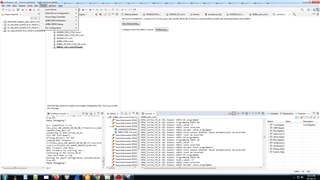
Device is set for the NO BOOT mode only.
--
Thanks & Regards,
Divyesh Patel
Hi Divyesh, i'm pretty sure your problem is that you are initializing the DDR twice (once using the javascript, and once using the GEL), this will result in failures. You should only do one or the other.
If you just run the javascript, it should be initializing the DDR, so be sure to put in the latest board_ddrReginit.h. Once this is run, you should not have to run any GELs. Just go directly to the read/write GEL script to test the memory.
Alternatively, you can run the GELs to setup the PLL/PSCs and initialize the DDR, just to see if you can access memory properly. You should not run the javascript after this. After the GELs are run, you can check the memory with the read/write GEL script
Regards,
James
Hi James,
I don't think so DDR initialized twice, I tried 3 methods and attached data of scripting console and console output. Please have a look.
Initializing ... (Completed)

js:> loadJSFile "C:\ti\mcu_plus_sdk_am243x_08_04_00_17\tools\ccs_load\am243x\load_dmsc.js"
Connecting to DMSC_Cortex_M3_0!
Fill R5F ATCM memory...
Writing While(1) for R5F
Loading DMSC Firmware ... C:/ti/mcu_plus_sdk_am243x_08_04_00_17//source/drivers/sciclient/soc/am64x_am243x/sysfw.bin
DMSC Firmware Load Done...
DMSC Firmware run starting now...
Connecting to MCU Cortex_R5_0!
 Main Boot Mode is 120
Running the board configuration initialization from R5!
Happy Debugging!!

js:>
and the output of console(including DDR initialization and write_read test) is
DMSC_Cortex_M3_0: GEL Output: Configuring ATCM for the R5Fs
DMSC_Cortex_M3_0: GEL Output: ATCM Configured.
DMSC_Cortex_M3_0: GEL Output: R5F Halt bits set.
DMSC_Cortex_M3_0: GEL Output: Configuring bootvectors
DMSC_Cortex_M3_0: GEL Output: Bootvectors configured.
DMSC_Cortex_M3_0: GEL Output: Running from DMSC
DMSC_Cortex_M3_0: GEL Output: Debugging enabled
DMSC_Cortex_M3_0: GEL Output: Programming all PLLs.
DMSC_Cortex_M3_0: GEL Output: Programming Main PLL 0 (Main PLL)
DMSC_Cortex_M3_0: GEL Output: Unlocked PLL MMRs.
DMSC_Cortex_M3_0: GEL Output: Read configuration MMRs.
DMSC_Cortex_M3_0: GEL Output: temp value (HSDIV_Presence) = 0x000003FF
DMSC_Cortex_M3_0: GEL Output: HSDIV presence value = 0x000003FF
DMSC_Cortex_M3_0: GEL Output: Number of hsidvs: 10
DMSC_Cortex_M3_0: GEL Output: Parsed PLL configuration information.
DMSC_Cortex_M3_0: GEL Output: Note: deskew PLL programming isn't implemented yet
DMSC_Cortex_M3_0: GEL Output: This is a fractional PLL, continuing on with normal programming.
DMSC_Cortex_M3_0: GEL Output: For debugging:
DMSC_Cortex_M3_0: GEL Output: Base address: 0x00680000
DMSC_Cortex_M3_0: GEL Output: PLL index: 0x00000000
DMSC_Cortex_M3_0: GEL Output: PLL index register base: 0x00000000
DMSC_Cortex_M3_0: GEL Output: Register: 0x00000020
DMSC_Cortex_M3_0: GEL Output: Clocking scheme: 1
DMSC_Cortex_M3_0: GEL Output: Set PLL to external bypass via Control MMR.
DMSC_Cortex_M3_0: GEL Output: Disabled PLL
DMSC_Cortex_M3_0: GEL Output: Enabled noise-cancelling DAC.
DMSC_Cortex_M3_0: GEL Output: Enabled the Delta-Sigma modulator.
DMSC_Cortex_M3_0: GEL Output: Programmed Reference clock pre-divider in output clock divider register.
DMSC_Cortex_M3_0: GEL Output: Programmed the integer feedback divider value in Freq Control 0 register.
DMSC_Cortex_M3_0: GEL Output: Fractional Divider Value is -1, don't set the fractional divider.
DMSC_Cortex_M3_0: GEL Output: Programmed the fractional feedback divider in Freq Control 0 register.
DMSC_Cortex_M3_0: GEL Output: Disabled the 4-phase clock generator (clk_4ph_en) in the control register.
DMSC_Cortex_M3_0: GEL Output: Enabled the FOUT4PHASE clocks in the control register.
DMSC_Cortex_M3_0: GEL Output: Set the first post-divider value (POSTDIV1) in the output divider control register.
DMSC_Cortex_M3_0: GEL Output: Set the second post-divider value (POSTDIV2) in the output divider control register.
DMSC_Cortex_M3_0: GEL Output: Programming HSDIV #0
DMSC_Cortex_M3_0: GEL Output: hsdiv_value: 3
DMSC_Cortex_M3_0: GEL Output: HSDIV reset asserted
DMSC_Cortex_M3_0: GEL Output: HSDIV divider value programmed.
DMSC_Cortex_M3_0: GEL Output: HSDIV clock output enabled. Reset automatically de-asserted.
DMSC_Cortex_M3_0: GEL Output: HSDIV reset de-asserted
DMSC_Cortex_M3_0: GEL Output: HSDIV #0 programmed.
DMSC_Cortex_M3_0: GEL Output: Programming HSDIV #1
DMSC_Cortex_M3_0: GEL Output: hsdiv_value: 9
DMSC_Cortex_M3_0: GEL Output: HSDIV reset asserted
DMSC_Cortex_M3_0: GEL Output: HSDIV divider value programmed.
DMSC_Cortex_M3_0: GEL Output: HSDIV clock output enabled. Reset automatically de-asserted.
DMSC_Cortex_M3_0: GEL Output: HSDIV reset de-asserted
DMSC_Cortex_M3_0: GEL Output: HSDIV #1 programmed.
DMSC_Cortex_M3_0: GEL Output: Programming HSDIV #2
DMSC_Cortex_M3_0: GEL Output: hsdiv_value: 24
DMSC_Cortex_M3_0: GEL Output: HSDIV reset asserted
DMSC_Cortex_M3_0: GEL Output: HSDIV divider value programmed.
DMSC_Cortex_M3_0: GEL Output: HSDIV clock output enabled. Reset automatically de-asserted.
DMSC_Cortex_M3_0: GEL Output: HSDIV reset de-asserted
DMSC_Cortex_M3_0: GEL Output: HSDIV #2 programmed.
DMSC_Cortex_M3_0: GEL Output: Programming HSDIV #3
DMSC_Cortex_M3_0: GEL Output: hsdiv_value: 14
DMSC_Cortex_M3_0: GEL Output: HSDIV reset asserted
DMSC_Cortex_M3_0: GEL Output: HSDIV divider value programmed.
DMSC_Cortex_M3_0: GEL Output: HSDIV clock output enabled. Reset automatically de-asserted.
DMSC_Cortex_M3_0: GEL Output: HSDIV reset de-asserted
DMSC_Cortex_M3_0: GEL Output: HSDIV #3 programmed.
DMSC_Cortex_M3_0: GEL Output: Programming HSDIV #4
DMSC_Cortex_M3_0: GEL Output: hsdiv_value: 7
DMSC_Cortex_M3_0: GEL Output: HSDIV reset asserted
DMSC_Cortex_M3_0: GEL Output: HSDIV divider value programmed.
DMSC_Cortex_M3_0: GEL Output: HSDIV clock output enabled. Reset automatically de-asserted.
DMSC_Cortex_M3_0: GEL Output: HSDIV reset de-asserted
DMSC_Cortex_M3_0: GEL Output: HSDIV #4 programmed.
DMSC_Cortex_M3_0: GEL Output: Programming HSDIV #5
DMSC_Cortex_M3_0: GEL Output: hsdiv_value: 4
DMSC_Cortex_M3_0: GEL Output: HSDIV reset asserted
DMSC_Cortex_M3_0: GEL Output: HSDIV divider value programmed.
DMSC_Cortex_M3_0: GEL Output: HSDIV clock output enabled. Reset automatically de-asserted.
DMSC_Cortex_M3_0: GEL Output: HSDIV reset de-asserted
DMSC_Cortex_M3_0: GEL Output: HSDIV #5 programmed.
DMSC_Cortex_M3_0: GEL Output: Programming HSDIV #6
DMSC_Cortex_M3_0: GEL Output: hsdiv_value: 3
DMSC_Cortex_M3_0: GEL Output: HSDIV reset asserted
DMSC_Cortex_M3_0: GEL Output: HSDIV divider value programmed.
DMSC_Cortex_M3_0: GEL Output: HSDIV clock output enabled. Reset automatically de-asserted.
DMSC_Cortex_M3_0: GEL Output: HSDIV reset de-asserted
DMSC_Cortex_M3_0: GEL Output: HSDIV #6 programmed.
DMSC_Cortex_M3_0: GEL Output: Programming HSDIV #7
DMSC_Cortex_M3_0: GEL Output: hsdiv_value: 3
DMSC_Cortex_M3_0: GEL Output: HSDIV reset asserted
DMSC_Cortex_M3_0: GEL Output: HSDIV divider value programmed.
DMSC_Cortex_M3_0: GEL Output: HSDIV clock output enabled. Reset automatically de-asserted.
DMSC_Cortex_M3_0: GEL Output: HSDIV reset de-asserted
DMSC_Cortex_M3_0: GEL Output: HSDIV #7 programmed.
DMSC_Cortex_M3_0: GEL Output: Programming HSDIV #8
DMSC_Cortex_M3_0: GEL Output: hsdiv_value: 7
DMSC_Cortex_M3_0: GEL Output: HSDIV reset asserted
DMSC_Cortex_M3_0: GEL Output: HSDIV divider value programmed.
DMSC_Cortex_M3_0: GEL Output: HSDIV clock output enabled. Reset automatically de-asserted.
DMSC_Cortex_M3_0: GEL Output: HSDIV reset de-asserted
DMSC_Cortex_M3_0: GEL Output: HSDIV #8 programmed.
DMSC_Cortex_M3_0: GEL Output: Programming HSDIV #9
DMSC_Cortex_M3_0: GEL Output: hsdiv_value: 2
DMSC_Cortex_M3_0: GEL Output: HSDIV reset asserted
DMSC_Cortex_M3_0: GEL Output: HSDIV divider value programmed.
DMSC_Cortex_M3_0: GEL Output: HSDIV clock output enabled. Reset automatically de-asserted.
DMSC_Cortex_M3_0: GEL Output: HSDIV reset de-asserted
DMSC_Cortex_M3_0: GEL Output: HSDIV #9 programmed.
DMSC_Cortex_M3_0: GEL Output: Selected Main Domain PLL Controller.
DMSC_Cortex_M3_0: GEL Output: Cleared bit 0 in the PLL controller control register.
DMSC_Cortex_M3_0: GEL Output: Cleared bit 5 in the PLL Controller control register.
DMSC_Cortex_M3_0: GEL Output: PLL controller is now in bypass mode.
DMSC_Cortex_M3_0: GEL Output: Set reset isolation to prevent a warm reset from killing the PLL controller.
DMSC_Cortex_M3_0: GEL Output: Set PLLDIV1 (output_div1).
DMSC_Cortex_M3_0: GEL Output: addr: 0x80410124 = 0x00008000
DMSC_Cortex_M3_0: GEL Output: Clear GOSET.
DMSC_Cortex_M3_0: GEL Output: GOSTAT is clear.
DMSC_Cortex_M3_0: GEL Output: Set PLLDIV1 (output_div1).
DMSC_Cortex_M3_0: GEL Output: Set ALN1.
DMSC_Cortex_M3_0: GEL Output: addr: 0x80410104 = 0x00000012
DMSC_Cortex_M3_0: GEL Output: Set OCSEL to 0x12, point C on the observation clock input tree inside the PLL Controller.
DMSC_Cortex_M3_0: GEL Output: addr: 0x80410148 = 0x00000002
DMSC_Cortex_M3_0: GEL Output: Set the clock control register to enable the OBSCLK output (bit 1).
DMSC_Cortex_M3_0: GEL Output: Set GOSET to 1.
DMSC_Cortex_M3_0: GEL Output: GOSTAT is clear.
DMSC_Cortex_M3_0: GEL Output: Enable PLL Controller (write to bit 0 in control register).
DMSC_Cortex_M3_0: GEL Output: Set GOSET to 0.
DMSC_Cortex_M3_0: GEL Output: PLLCTRL reset is cleared. PLLCTRL is free.
DMSC_Cortex_M3_0: GEL Output: Set the enable bit in the control register.
DMSC_Cortex_M3_0: GEL Output: PLL is locked.
DMSC_Cortex_M3_0: GEL Output: External bypass is disabled '0'. PLL and HSDIV clocks are engaging the rest of the SoC.
DMSC_Cortex_M3_0: GEL Output: Main PLL 0 (Main PLL) Set.
DMSC_Cortex_M3_0: GEL Output: Programming Main PLL 1 (Peripheral 0 PLL)
DMSC_Cortex_M3_0: GEL Output: Unlocked PLL MMRs.
DMSC_Cortex_M3_0: GEL Output: Read configuration MMRs.
DMSC_Cortex_M3_0: GEL Output: temp value (HSDIV_Presence) = 0x0000007F
DMSC_Cortex_M3_0: GEL Output: HSDIV presence value = 0x0000007F
DMSC_Cortex_M3_0: GEL Output: Number of hsidvs: 7
DMSC_Cortex_M3_0: GEL Output: Parsed PLL configuration information.
DMSC_Cortex_M3_0: GEL Output: Note: deskew PLL programming isn't implemented yet
DMSC_Cortex_M3_0: GEL Output: This is a fractional PLL, continuing on with normal programming.
DMSC_Cortex_M3_0: GEL Output: For debugging:
DMSC_Cortex_M3_0: GEL Output: Base address: 0x00680000
DMSC_Cortex_M3_0: GEL Output: PLL index: 0x00000001
DMSC_Cortex_M3_0: GEL Output: PLL index register base: 0x00001000
DMSC_Cortex_M3_0: GEL Output: Register: 0x00000020
DMSC_Cortex_M3_0: GEL Output: Clocking scheme: 1
DMSC_Cortex_M3_0: GEL Output: Set PLL to external bypass via Control MMR.
DMSC_Cortex_M3_0: GEL Output: Disabled PLL
DMSC_Cortex_M3_0: GEL Output: Enabled noise-cancelling DAC.
DMSC_Cortex_M3_0: GEL Output: Enabled the Delta-Sigma modulator.
DMSC_Cortex_M3_0: GEL Output: Programmed Reference clock pre-divider in output clock divider register.
DMSC_Cortex_M3_0: GEL Output: Programmed the integer feedback divider value in Freq Control 0 register.
DMSC_Cortex_M3_0: GEL Output: Fractional Divider Value is -1, don't set the fractional divider.
DMSC_Cortex_M3_0: GEL Output: Programmed the fractional feedback divider in Freq Control 0 register.
DMSC_Cortex_M3_0: GEL Output: Disabled the 4-phase clock generator (clk_4ph_en) in the control register.
DMSC_Cortex_M3_0: GEL Output: Enabled the FOUT4PHASE clocks in the control register.
DMSC_Cortex_M3_0: GEL Output: Set the first post-divider value (POSTDIV1) in the output divider control register.
DMSC_Cortex_M3_0: GEL Output: Set the second post-divider value (POSTDIV2) in the output divider control register.
DMSC_Cortex_M3_0: GEL Output: Programming HSDIV #0
DMSC_Cortex_M3_0: GEL Output: hsdiv_value: 9
DMSC_Cortex_M3_0: GEL Output: HSDIV reset asserted
DMSC_Cortex_M3_0: GEL Output: HSDIV divider value programmed.
DMSC_Cortex_M3_0: GEL Output: HSDIV clock output enabled. Reset automatically de-asserted.
DMSC_Cortex_M3_0: GEL Output: HSDIV reset de-asserted
DMSC_Cortex_M3_0: GEL Output: HSDIV #0 programmed.
DMSC_Cortex_M3_0: GEL Output: Programming HSDIV #1
DMSC_Cortex_M3_0: GEL Output: hsdiv_value: 11
DMSC_Cortex_M3_0: GEL Output: HSDIV reset asserted
DMSC_Cortex_M3_0: GEL Output: HSDIV divider value programmed.
DMSC_Cortex_M3_0: GEL Output: HSDIV clock output enabled. Reset automatically de-asserted.
DMSC_Cortex_M3_0: GEL Output: HSDIV reset de-asserted
DMSC_Cortex_M3_0: GEL Output: HSDIV #1 programmed.
DMSC_Cortex_M3_0: GEL Output: Programming HSDIV #2
DMSC_Cortex_M3_0: GEL Output: hsdiv_value: 4
DMSC_Cortex_M3_0: GEL Output: HSDIV reset asserted
DMSC_Cortex_M3_0: GEL Output: HSDIV divider value programmed.
DMSC_Cortex_M3_0: GEL Output: HSDIV clock output enabled. Reset automatically de-asserted.
DMSC_Cortex_M3_0: GEL Output: HSDIV reset de-asserted
DMSC_Cortex_M3_0: GEL Output: HSDIV #2 programmed.
DMSC_Cortex_M3_0: GEL Output: Programming HSDIV #3
DMSC_Cortex_M3_0: GEL Output: hsdiv_value: 9
DMSC_Cortex_M3_0: GEL Output: HSDIV reset asserted
DMSC_Cortex_M3_0: GEL Output: HSDIV divider value programmed.
DMSC_Cortex_M3_0: GEL Output: HSDIV clock output enabled. Reset automatically de-asserted.
DMSC_Cortex_M3_0: GEL Output: HSDIV reset de-asserted
DMSC_Cortex_M3_0: GEL Output: HSDIV #3 programmed.
DMSC_Cortex_M3_0: GEL Output: Programming HSDIV #4
DMSC_Cortex_M3_0: GEL Output: hsdiv_value: 79
DMSC_Cortex_M3_0: GEL Output: HSDIV reset asserted
DMSC_Cortex_M3_0: GEL Output: HSDIV divider value programmed.
DMSC_Cortex_M3_0: GEL Output: HSDIV clock output enabled. Reset automatically de-asserted.
DMSC_Cortex_M3_0: GEL Output: HSDIV reset de-asserted
DMSC_Cortex_M3_0: GEL Output: HSDIV #4 programmed.
DMSC_Cortex_M3_0: GEL Output: Programming HSDIV #5
DMSC_Cortex_M3_0: GEL Output: hsdiv_value: 5
DMSC_Cortex_M3_0: GEL Output: HSDIV reset asserted
DMSC_Cortex_M3_0: GEL Output: HSDIV divider value programmed.
DMSC_Cortex_M3_0: GEL Output: HSDIV clock output enabled. Reset automatically de-asserted.
DMSC_Cortex_M3_0: GEL Output: HSDIV reset de-asserted
DMSC_Cortex_M3_0: GEL Output: HSDIV #5 programmed.
DMSC_Cortex_M3_0: GEL Output: Programming HSDIV #6
DMSC_Cortex_M3_0: GEL Output: hsdiv_value: 15
DMSC_Cortex_M3_0: GEL Output: HSDIV reset asserted
DMSC_Cortex_M3_0: GEL Output: HSDIV divider value programmed.
DMSC_Cortex_M3_0: GEL Output: HSDIV clock output enabled. Reset automatically de-asserted.
DMSC_Cortex_M3_0: GEL Output: HSDIV reset de-asserted
DMSC_Cortex_M3_0: GEL Output: HSDIV #6 programmed.
DMSC_Cortex_M3_0: GEL Output: Set the enable bit in the control register.
DMSC_Cortex_M3_0: GEL Output: PLL is locked.
DMSC_Cortex_M3_0: GEL Output: External bypass is disabled '0'. PLL and HSDIV clocks are engaging the rest of the SoC.
DMSC_Cortex_M3_0: GEL Output: Main PLL 1 (Peripheral 0 PLL) Set.
DMSC_Cortex_M3_0: GEL Output: Programming Main PLL 2 (Peripheral 1 PLL)
DMSC_Cortex_M3_0: GEL Output: Unlocked PLL MMRs.
DMSC_Cortex_M3_0: GEL Output: Read configuration MMRs.
DMSC_Cortex_M3_0: GEL Output: temp value (HSDIV_Presence) = 0x000003FF
DMSC_Cortex_M3_0: GEL Output: HSDIV presence value = 0x000003FF
DMSC_Cortex_M3_0: GEL Output: Number of hsidvs: 10
DMSC_Cortex_M3_0: GEL Output: Parsed PLL configuration information.
DMSC_Cortex_M3_0: GEL Output: Note: deskew PLL programming isn't implemented yet
DMSC_Cortex_M3_0: GEL Output: This is a fractional PLL, continuing on with normal programming.
DMSC_Cortex_M3_0: GEL Output: For debugging:
DMSC_Cortex_M3_0: GEL Output: Base address: 0x00680000
DMSC_Cortex_M3_0: GEL Output: PLL index: 0x00000002
DMSC_Cortex_M3_0: GEL Output: PLL index register base: 0x00002000
DMSC_Cortex_M3_0: GEL Output: Register: 0x00000020
DMSC_Cortex_M3_0: GEL Output: Clocking scheme: 1
DMSC_Cortex_M3_0: GEL Output: Set PLL to external bypass via Control MMR.
DMSC_Cortex_M3_0: GEL Output: Disabled PLL
DMSC_Cortex_M3_0: GEL Output: Enabled noise-cancelling DAC.
DMSC_Cortex_M3_0: GEL Output: Enabled the Delta-Sigma modulator.
DMSC_Cortex_M3_0: GEL Output: Programmed Reference clock pre-divider in output clock divider register.
DMSC_Cortex_M3_0: GEL Output: Programmed the integer feedback divider value in Freq Control 0 register.
DMSC_Cortex_M3_0: GEL Output: Fractional Divider Value is -1, don't set the fractional divider.
DMSC_Cortex_M3_0: GEL Output: Programmed the fractional feedback divider in Freq Control 0 register.
DMSC_Cortex_M3_0: GEL Output: Disabled the 4-phase clock generator (clk_4ph_en) in the control register.
DMSC_Cortex_M3_0: GEL Output: Enabled the FOUT4PHASE clocks in the control register.
DMSC_Cortex_M3_0: GEL Output: Set the first post-divider value (POSTDIV1) in the output divider control register.
DMSC_Cortex_M3_0: GEL Output: Set the second post-divider value (POSTDIV2) in the output divider control register.
DMSC_Cortex_M3_0: GEL Output: Programming HSDIV #0
DMSC_Cortex_M3_0: GEL Output: hsdiv_value: 5
DMSC_Cortex_M3_0: GEL Output: HSDIV reset asserted
DMSC_Cortex_M3_0: GEL Output: HSDIV divider value programmed.
DMSC_Cortex_M3_0: GEL Output: HSDIV clock output enabled. Reset automatically de-asserted.
DMSC_Cortex_M3_0: GEL Output: HSDIV reset de-asserted
DMSC_Cortex_M3_0: GEL Output: HSDIV #0 programmed.
DMSC_Cortex_M3_0: GEL Output: Programming HSDIV #1
DMSC_Cortex_M3_0: GEL Output: i: 1, HSDIV value is -1, don't program this one
DMSC_Cortex_M3_0: GEL Output: HSDIV clock output disabled.
DMSC_Cortex_M3_0: GEL Output: HSDIV #1 programmed.
DMSC_Cortex_M3_0: GEL Output: Programming HSDIV #2
DMSC_Cortex_M3_0: GEL Output: hsdiv_value: 8
DMSC_Cortex_M3_0: GEL Output: HSDIV reset asserted
DMSC_Cortex_M3_0: GEL Output: HSDIV divider value programmed.
DMSC_Cortex_M3_0: GEL Output: HSDIV clock output enabled. Reset automatically de-asserted.
DMSC_Cortex_M3_0: GEL Output: HSDIV reset de-asserted
DMSC_Cortex_M3_0: GEL Output: HSDIV #2 programmed.
DMSC_Cortex_M3_0: GEL Output: Programming HSDIV #3
DMSC_Cortex_M3_0: GEL Output: hsdiv_value: 5
DMSC_Cortex_M3_0: GEL Output: HSDIV reset asserted
DMSC_Cortex_M3_0: GEL Output: HSDIV divider value programmed.
DMSC_Cortex_M3_0: GEL Output: HSDIV clock output enabled. Reset automatically de-asserted.
DMSC_Cortex_M3_0: GEL Output: HSDIV reset de-asserted
DMSC_Cortex_M3_0: GEL Output: HSDIV #3 programmed.
DMSC_Cortex_M3_0: GEL Output: Programming HSDIV #4
DMSC_Cortex_M3_0: GEL Output: hsdiv_value: 17
DMSC_Cortex_M3_0: GEL Output: HSDIV reset asserted
DMSC_Cortex_M3_0: GEL Output: HSDIV divider value programmed.
DMSC_Cortex_M3_0: GEL Output: HSDIV clock output enabled. Reset automatically de-asserted.
DMSC_Cortex_M3_0: GEL Output: HSDIV reset de-asserted
DMSC_Cortex_M3_0: GEL Output: HSDIV #4 programmed.
DMSC_Cortex_M3_0: GEL Output: Programming HSDIV #5
DMSC_Cortex_M3_0: GEL Output: hsdiv_value: 7
DMSC_Cortex_M3_0: GEL Output: HSDIV reset asserted
DMSC_Cortex_M3_0: GEL Output: HSDIV divider value programmed.
DMSC_Cortex_M3_0: GEL Output: HSDIV clock output enabled. Reset automatically de-asserted.
DMSC_Cortex_M3_0: GEL Output: HSDIV reset de-asserted
DMSC_Cortex_M3_0: GEL Output: HSDIV #5 programmed.
DMSC_Cortex_M3_0: GEL Output: Programming HSDIV #6
DMSC_Cortex_M3_0: GEL Output: hsdiv_value: 7
DMSC_Cortex_M3_0: GEL Output: HSDIV reset asserted
DMSC_Cortex_M3_0: GEL Output: HSDIV divider value programmed.
DMSC_Cortex_M3_0: GEL Output: HSDIV clock output enabled. Reset automatically de-asserted.
DMSC_Cortex_M3_0: GEL Output: HSDIV reset de-asserted
DMSC_Cortex_M3_0: GEL Output: HSDIV #6 programmed.
DMSC_Cortex_M3_0: GEL Output: Programming HSDIV #7
DMSC_Cortex_M3_0: GEL Output: hsdiv_value: 17
DMSC_Cortex_M3_0: GEL Output: HSDIV reset asserted
DMSC_Cortex_M3_0: GEL Output: HSDIV divider value programmed.
DMSC_Cortex_M3_0: GEL Output: HSDIV clock output enabled. Reset automatically de-asserted.
DMSC_Cortex_M3_0: GEL Output: HSDIV reset de-asserted
DMSC_Cortex_M3_0: GEL Output: HSDIV #7 programmed.
DMSC_Cortex_M3_0: GEL Output: Programming HSDIV #8
DMSC_Cortex_M3_0: GEL Output: i: 8, HSDIV value is -1, don't program this one
DMSC_Cortex_M3_0: GEL Output: HSDIV clock output disabled.
DMSC_Cortex_M3_0: GEL Output: HSDIV #8 programmed.
DMSC_Cortex_M3_0: GEL Output: Programming HSDIV #9
DMSC_Cortex_M3_0: GEL Output: hsdiv_value: 4
DMSC_Cortex_M3_0: GEL Output: HSDIV reset asserted
DMSC_Cortex_M3_0: GEL Output: HSDIV divider value programmed.
DMSC_Cortex_M3_0: GEL Output: HSDIV clock output enabled. Reset automatically de-asserted.
DMSC_Cortex_M3_0: GEL Output: HSDIV reset de-asserted
DMSC_Cortex_M3_0: GEL Output: HSDIV #9 programmed.
DMSC_Cortex_M3_0: GEL Output: Set the enable bit in the control register.
DMSC_Cortex_M3_0: GEL Output: PLL is locked.
DMSC_Cortex_M3_0: GEL Output: External bypass is disabled '0'. PLL and HSDIV clocks are engaging the rest of the SoC.
DMSC_Cortex_M3_0: GEL Output: Main PLL 2 (Peripheral 1 PLL) Set.
DMSC_Cortex_M3_0: GEL Output: Programming Main PLL 8 (ARM0 PLL)
DMSC_Cortex_M3_0: GEL Output: Unlocked PLL MMRs.
DMSC_Cortex_M3_0: GEL Output: Read configuration MMRs.
DMSC_Cortex_M3_0: GEL Output: temp value (HSDIV_Presence) = 0x00000001
DMSC_Cortex_M3_0: GEL Output: HSDIV presence value = 0x00000001
DMSC_Cortex_M3_0: GEL Output: Number of hsidvs: 1
DMSC_Cortex_M3_0: GEL Output: Parsed PLL configuration information.
DMSC_Cortex_M3_0: GEL Output: Note: deskew PLL programming isn't implemented yet
DMSC_Cortex_M3_0: GEL Output: This is a fractional PLL, continuing on with normal programming.
DMSC_Cortex_M3_0: GEL Output: For debugging:
DMSC_Cortex_M3_0: GEL Output: Base address: 0x00680000
DMSC_Cortex_M3_0: GEL Output: PLL index: 0x00000008
DMSC_Cortex_M3_0: GEL Output: PLL index register base: 0x00008000
DMSC_Cortex_M3_0: GEL Output: Register: 0x00000020
DMSC_Cortex_M3_0: GEL Output: Clocking scheme: 1
DMSC_Cortex_M3_0: GEL Output: Set PLL to external bypass via Control MMR.
DMSC_Cortex_M3_0: GEL Output: Disabled PLL
DMSC_Cortex_M3_0: GEL Output: Enabled noise-cancelling DAC.
DMSC_Cortex_M3_0: GEL Output: Enabled the Delta-Sigma modulator.
DMSC_Cortex_M3_0: GEL Output: Programmed Reference clock pre-divider in output clock divider register.
DMSC_Cortex_M3_0: GEL Output: Programmed the integer feedback divider value in Freq Control 0 register.
DMSC_Cortex_M3_0: GEL Output: Fractional Divider Value is -1, don't set the fractional divider.
DMSC_Cortex_M3_0: GEL Output: Programmed the fractional feedback divider in Freq Control 0 register.
DMSC_Cortex_M3_0: GEL Output: Disabled the 4-phase clock generator (clk_4ph_en) in the control register.
DMSC_Cortex_M3_0: GEL Output: Enabled the FOUT4PHASE clocks in the control register.
DMSC_Cortex_M3_0: GEL Output: Set the first post-divider value (POSTDIV1) in the output divider control register.
DMSC_Cortex_M3_0: GEL Output: Set the second post-divider value (POSTDIV2) in the output divider control register.
DMSC_Cortex_M3_0: GEL Output: Programming HSDIV #0
DMSC_Cortex_M3_0: GEL Output: hsdiv_value: 1
DMSC_Cortex_M3_0: GEL Output: HSDIV reset asserted
DMSC_Cortex_M3_0: GEL Output: HSDIV divider value programmed.
DMSC_Cortex_M3_0: GEL Output: HSDIV clock output enabled. Reset automatically de-asserted.
DMSC_Cortex_M3_0: GEL Output: HSDIV reset de-asserted
DMSC_Cortex_M3_0: GEL Output: HSDIV #0 programmed.
DMSC_Cortex_M3_0: GEL Output: Set the enable bit in the control register.
DMSC_Cortex_M3_0: GEL Output: PLL is locked.
DMSC_Cortex_M3_0: GEL Output: External bypass is disabled '0'. PLL and HSDIV clocks are engaging the rest of the SoC.
DMSC_Cortex_M3_0: GEL Output: Main PLL 8 (ARM0 PLL) Set.
DMSC_Cortex_M3_0: GEL Output: Programming Main PLL 12 (DDR PLL)
DMSC_Cortex_M3_0: GEL Output: Unlocked PLL MMRs.
DMSC_Cortex_M3_0: GEL Output: Read configuration MMRs.
DMSC_Cortex_M3_0: GEL Output: temp value (HSDIV_Presence) = 0x00000001
DMSC_Cortex_M3_0: GEL Output: HSDIV presence value = 0x00000001
DMSC_Cortex_M3_0: GEL Output: Number of hsidvs: 1
DMSC_Cortex_M3_0: GEL Output: Parsed PLL configuration information.
DMSC_Cortex_M3_0: GEL Output: Note: deskew PLL programming isn't implemented yet
DMSC_Cortex_M3_0: GEL Output: This is a fractional PLL, continuing on with normal programming.
DMSC_Cortex_M3_0: GEL Output: For debugging:
DMSC_Cortex_M3_0: GEL Output: Base address: 0x00680000
DMSC_Cortex_M3_0: GEL Output: PLL index: 0x0000000C
DMSC_Cortex_M3_0: GEL Output: PLL index register base: 0x0000C000
DMSC_Cortex_M3_0: GEL Output: Register: 0x00000020
DMSC_Cortex_M3_0: GEL Output: Clocking scheme: 1
DMSC_Cortex_M3_0: GEL Output: Set PLL to external bypass via Control MMR.
DMSC_Cortex_M3_0: GEL Output: Disabled PLL
DMSC_Cortex_M3_0: GEL Output: Enabled noise-cancelling DAC.
DMSC_Cortex_M3_0: GEL Output: Enabled the Delta-Sigma modulator.
DMSC_Cortex_M3_0: GEL Output: Programmed Reference clock pre-divider in output clock divider register.
DMSC_Cortex_M3_0: GEL Output: Programmed the integer feedback divider value in Freq Control 0 register.
DMSC_Cortex_M3_0: GEL Output: Fractional Divider Value is -1, don't set the fractional divider.
DMSC_Cortex_M3_0: GEL Output: Programmed the fractional feedback divider in Freq Control 0 register.
DMSC_Cortex_M3_0: GEL Output: Disabled the 4-phase clock generator (clk_4ph_en) in the control register.
DMSC_Cortex_M3_0: GEL Output: Enabled the FOUT4PHASE clocks in the control register.
DMSC_Cortex_M3_0: GEL Output: Set the first post-divider value (POSTDIV1) in the output divider control register.
DMSC_Cortex_M3_0: GEL Output: Set the second post-divider value (POSTDIV2) in the output divider control register.
DMSC_Cortex_M3_0: GEL Output: Programming HSDIV #0
DMSC_Cortex_M3_0: GEL Output: hsdiv_value: 3
DMSC_Cortex_M3_0: GEL Output: HSDIV reset asserted
DMSC_Cortex_M3_0: GEL Output: HSDIV divider value programmed.
DMSC_Cortex_M3_0: GEL Output: HSDIV clock output enabled. Reset automatically de-asserted.
DMSC_Cortex_M3_0: GEL Output: HSDIV reset de-asserted
DMSC_Cortex_M3_0: GEL Output: HSDIV #0 programmed.
DMSC_Cortex_M3_0: GEL Output: Set the enable bit in the control register.
DMSC_Cortex_M3_0: GEL Output: PLL is locked.
DMSC_Cortex_M3_0: GEL Output: External bypass is disabled '0'. PLL and HSDIV clocks are engaging the rest of the SoC.
DMSC_Cortex_M3_0: GEL Output: Main PLL 12 (DDR PLL) Set.
DMSC_Cortex_M3_0: GEL Output: Programming Main PLL 14 (Main Domain Pulsar) PLL)
DMSC_Cortex_M3_0: GEL Output: Unlocked PLL MMRs.
DMSC_Cortex_M3_0: GEL Output: Read configuration MMRs.
DMSC_Cortex_M3_0: GEL Output: temp value (HSDIV_Presence) = 0x00000003
DMSC_Cortex_M3_0: GEL Output: HSDIV presence value = 0x00000003
DMSC_Cortex_M3_0: GEL Output: Number of hsidvs: 2
DMSC_Cortex_M3_0: GEL Output: Parsed PLL configuration information.
DMSC_Cortex_M3_0: GEL Output: Note: deskew PLL programming isn't implemented yet
DMSC_Cortex_M3_0: GEL Output: This is a fractional PLL, continuing on with normal programming.
DMSC_Cortex_M3_0: GEL Output: For debugging:
DMSC_Cortex_M3_0: GEL Output: Base address: 0x00680000
DMSC_Cortex_M3_0: GEL Output: PLL index: 0x0000000E
DMSC_Cortex_M3_0: GEL Output: PLL index register base: 0x0000E000
DMSC_Cortex_M3_0: GEL Output: Register: 0x00000020
DMSC_Cortex_M3_0: GEL Output: Clocking scheme: 1
DMSC_Cortex_M3_0: GEL Output: Set PLL to external bypass via Control MMR.
DMSC_Cortex_M3_0: GEL Output: Disabled PLL
DMSC_Cortex_M3_0: GEL Output: Enabled noise-cancelling DAC.
DMSC_Cortex_M3_0: GEL Output: Enabled the Delta-Sigma modulator.
DMSC_Cortex_M3_0: GEL Output: Programmed Reference clock pre-divider in output clock divider register.
DMSC_Cortex_M3_0: GEL Output: Programmed the integer feedback divider value in Freq Control 0 register.
DMSC_Cortex_M3_0: GEL Output: Fractional Divider Value is -1, don't set the fractional divider.
DMSC_Cortex_M3_0: GEL Output: Programmed the fractional feedback divider in Freq Control 0 register.
DMSC_Cortex_M3_0: GEL Output: Disabled the 4-phase clock generator (clk_4ph_en) in the control register.
DMSC_Cortex_M3_0: GEL Output: Enabled the FOUT4PHASE clocks in the control register.
DMSC_Cortex_M3_0: GEL Output: Set the first post-divider value (POSTDIV1) in the output divider control register.
DMSC_Cortex_M3_0: GEL Output: Set the second post-divider value (POSTDIV2) in the output divider control register.
DMSC_Cortex_M3_0: GEL Output: Programming HSDIV #0
DMSC_Cortex_M3_0: GEL Output: hsdiv_value: 2
DMSC_Cortex_M3_0: GEL Output: HSDIV reset asserted
DMSC_Cortex_M3_0: GEL Output: HSDIV divider value programmed.
DMSC_Cortex_M3_0: GEL Output: HSDIV clock output enabled. Reset automatically de-asserted.
DMSC_Cortex_M3_0: GEL Output: HSDIV reset de-asserted
DMSC_Cortex_M3_0: GEL Output: HSDIV #0 programmed.
DMSC_Cortex_M3_0: GEL Output: Programming HSDIV #1
DMSC_Cortex_M3_0: GEL Output: hsdiv_value: 2
DMSC_Cortex_M3_0: GEL Output: HSDIV reset asserted
DMSC_Cortex_M3_0: GEL Output: HSDIV divider value programmed.
DMSC_Cortex_M3_0: GEL Output: HSDIV clock output enabled. Reset automatically de-asserted.
DMSC_Cortex_M3_0: GEL Output: HSDIV reset de-asserted
DMSC_Cortex_M3_0: GEL Output: HSDIV #1 programmed.
DMSC_Cortex_M3_0: GEL Output: Set the enable bit in the control register.
DMSC_Cortex_M3_0: GEL Output: PLL is locked.
DMSC_Cortex_M3_0: GEL Output: External bypass is disabled '0'. PLL and HSDIV clocks are engaging the rest of the SoC.
DMSC_Cortex_M3_0: GEL Output: Main PLL 14 (Main Domain Pulsar PLL) Set.
DMSC_Cortex_M3_0: GEL Output: Programming MCU PLL 0 (MCU PLL)
DMSC_Cortex_M3_0: GEL Output: Unlocked PLL MMRs.
DMSC_Cortex_M3_0: GEL Output: Read configuration MMRs.
DMSC_Cortex_M3_0: GEL Output: temp value (HSDIV_Presence) = 0x0000001F
DMSC_Cortex_M3_0: GEL Output: HSDIV presence value = 0x0000001F
DMSC_Cortex_M3_0: GEL Output: Number of hsidvs: 5
DMSC_Cortex_M3_0: GEL Output: Parsed PLL configuration information.
DMSC_Cortex_M3_0: GEL Output: Note: deskew PLL programming isn't implemented yet
DMSC_Cortex_M3_0: GEL Output: This is a fractional PLL, continuing on with normal programming.
DMSC_Cortex_M3_0: GEL Output: For debugging:
DMSC_Cortex_M3_0: GEL Output: Base address: 0x04040000
DMSC_Cortex_M3_0: GEL Output: PLL index: 0x00000000
DMSC_Cortex_M3_0: GEL Output: PLL index register base: 0x00000000
DMSC_Cortex_M3_0: GEL Output: Register: 0x00000020
DMSC_Cortex_M3_0: GEL Output: Clocking scheme: 1
DMSC_Cortex_M3_0: GEL Output: Set PLL to external bypass via Control MMR.
DMSC_Cortex_M3_0: GEL Output: Disabled PLL
DMSC_Cortex_M3_0: GEL Output: Enabled noise-cancelling DAC.
DMSC_Cortex_M3_0: GEL Output: Enabled the Delta-Sigma modulator.
DMSC_Cortex_M3_0: GEL Output: Programmed Reference clock pre-divider in output clock divider register.
DMSC_Cortex_M3_0: GEL Output: Programmed the integer feedback divider value in Freq Control 0 register.
DMSC_Cortex_M3_0: GEL Output: Fractional Divider Value is -1, don't set the fractional divider.
DMSC_Cortex_M3_0: GEL Output: Programmed the fractional feedback divider in Freq Control 0 register.
DMSC_Cortex_M3_0: GEL Output: Disabled the 4-phase clock generator (clk_4ph_en) in the control register.
DMSC_Cortex_M3_0: GEL Output: Enabled the FOUT4PHASE clocks in the control register.
DMSC_Cortex_M3_0: GEL Output: Set the first post-divider value (POSTDIV1) in the output divider control register.
DMSC_Cortex_M3_0: GEL Output: Set the second post-divider value (POSTDIV2) in the output divider control register.
DMSC_Cortex_M3_0: GEL Output: Programming HSDIV #0
DMSC_Cortex_M3_0: GEL Output: hsdiv_value: 5
DMSC_Cortex_M3_0: GEL Output: HSDIV reset asserted
DMSC_Cortex_M3_0: GEL Output: HSDIV divider value programmed.
DMSC_Cortex_M3_0: GEL Output: HSDIV clock output enabled. Reset automatically de-asserted.
DMSC_Cortex_M3_0: GEL Output: HSDIV reset de-asserted
DMSC_Cortex_M3_0: GEL Output: HSDIV #0 programmed.
DMSC_Cortex_M3_0: GEL Output: Programming HSDIV #1
DMSC_Cortex_M3_0: GEL Output: hsdiv_value: 24
DMSC_Cortex_M3_0: GEL Output: HSDIV reset asserted
DMSC_Cortex_M3_0: GEL Output: HSDIV divider value programmed.
DMSC_Cortex_M3_0: GEL Output: HSDIV clock output enabled. Reset automatically de-asserted.
DMSC_Cortex_M3_0: GEL Output: HSDIV reset de-asserted
DMSC_Cortex_M3_0: GEL Output: HSDIV #1 programmed.
DMSC_Cortex_M3_0: GEL Output: Programming HSDIV #2
DMSC_Cortex_M3_0: GEL Output: hsdiv_value: 24
DMSC_Cortex_M3_0: GEL Output: HSDIV reset asserted
DMSC_Cortex_M3_0: GEL Output: HSDIV divider value programmed.
DMSC_Cortex_M3_0: GEL Output: HSDIV clock output enabled. Reset automatically de-asserted.
DMSC_Cortex_M3_0: GEL Output: HSDIV reset de-asserted
DMSC_Cortex_M3_0: GEL Output: HSDIV #2 programmed.
DMSC_Cortex_M3_0: GEL Output: Programming HSDIV #3
DMSC_Cortex_M3_0: GEL Output: hsdiv_value: 11
DMSC_Cortex_M3_0: GEL Output: HSDIV reset asserted
DMSC_Cortex_M3_0: GEL Output: HSDIV divider value programmed.
DMSC_Cortex_M3_0: GEL Output: HSDIV clock output enabled. Reset automatically de-asserted.
DMSC_Cortex_M3_0: GEL Output: HSDIV reset de-asserted
DMSC_Cortex_M3_0: GEL Output: HSDIV #3 programmed.
DMSC_Cortex_M3_0: GEL Output: Programming HSDIV #4
DMSC_Cortex_M3_0: GEL Output: hsdiv_value: 11
DMSC_Cortex_M3_0: GEL Output: HSDIV reset asserted
DMSC_Cortex_M3_0: GEL Output: HSDIV divider value programmed.
DMSC_Cortex_M3_0: GEL Output: HSDIV clock output enabled. Reset automatically de-asserted.
DMSC_Cortex_M3_0: GEL Output: HSDIV reset de-asserted
DMSC_Cortex_M3_0: GEL Output: HSDIV #4 programmed.
DMSC_Cortex_M3_0: GEL Output: Selected MCU Domain PLL Conntroller.
DMSC_Cortex_M3_0: GEL Output: Cleared bit 0 in the PLL controller control register.
DMSC_Cortex_M3_0: GEL Output: Cleared bit 5 in the PLL Controller control register.
DMSC_Cortex_M3_0: GEL Output: PLL controller is now in bypass mode.
DMSC_Cortex_M3_0: GEL Output: Set reset isolation to prevent a warm reset from killing the PLL controller.
DMSC_Cortex_M3_0: GEL Output: Set PLLDIV1 (output_div1).
DMSC_Cortex_M3_0: GEL Output: addr: 0x84020124 = 0x00008000
DMSC_Cortex_M3_0: GEL Output: Clear GOSET.
DMSC_Cortex_M3_0: GEL Output: GOSTAT is clear.
DMSC_Cortex_M3_0: GEL Output: Set PLLDIV1 (output_div1).
DMSC_Cortex_M3_0: GEL Output: Set ALN1.
DMSC_Cortex_M3_0: GEL Output: addr: 0x84020104 = 0x00000012
DMSC_Cortex_M3_0: GEL Output: Set OCSEL to 0x12, point C on the observation clock input tree inside the PLL Controller.
DMSC_Cortex_M3_0: GEL Output: addr: 0x84020148 = 0x00000002
DMSC_Cortex_M3_0: GEL Output: Set the clock control register to enable the OBSCLK output (bit 1).
DMSC_Cortex_M3_0: GEL Output: Set GOSET to 1.
DMSC_Cortex_M3_0: GEL Output: GOSTAT is clear.
DMSC_Cortex_M3_0: GEL Output: Enable PLL Controller (write to bit 0 in control register).
DMSC_Cortex_M3_0: GEL Output: Set GOSET to 0.
DMSC_Cortex_M3_0: GEL Output: PLLCTRL reset is cleared. PLLCTRL is free.
DMSC_Cortex_M3_0: GEL Output: Set the enable bit in the control register.
DMSC_Cortex_M3_0: GEL Output: PLL is locked.
DMSC_Cortex_M3_0: GEL Output: External bypass is disabled '0'. PLL and HSDIV clocks are engaging the rest of the SoC.
DMSC_Cortex_M3_0: GEL Output: MCU PLL 0 (MCU PLL) Set.
DMSC_Cortex_M3_0: GEL Output: All PLLs programmed.
DMSC_Cortex_M3_0: GEL Output: Powering up all PSC power domains in progress...
DMSC_Cortex_M3_0: GEL Output: Powering up MAIN domain peripherals...
DMSC_Cortex_M3_0: GEL Output: Powering up GP_CORE_CTL.
DMSC_Cortex_M3_0: GEL Output: Powering up LPSC_DMSC
DMSC_Cortex_M3_0: GEL Output: Running from DMSC
DMSC_Cortex_M3_0: GEL Output: No change needed.
DMSC_Cortex_M3_0: GEL Output: Powering up LPSC_MAIN_TEST
DMSC_Cortex_M3_0: GEL Output: Running from DMSC
DMSC_Cortex_M3_0: GEL Output: No change needed.
DMSC_Cortex_M3_0: GEL Output: Powering up LPSC_MAIN_PBIST
DMSC_Cortex_M3_0: GEL Output: Running from DMSC
DMSC_Cortex_M3_0: GEL Output: No change needed.
DMSC_Cortex_M3_0: GEL Output: Powering up LPSC_EMMC_4B
DMSC_Cortex_M3_0: GEL Output: Running from DMSC
DMSC_Cortex_M3_0: GEL Output: Power domain and module state changed successfully.
DMSC_Cortex_M3_0: GEL Output: Powering up LPSC_EMMC_8B
DMSC_Cortex_M3_0: GEL Output: Running from DMSC
DMSC_Cortex_M3_0: GEL Output: Power domain and module state changed successfully.
DMSC_Cortex_M3_0: GEL Output: Powering up LPSC_USB
DMSC_Cortex_M3_0: GEL Output: Running from DMSC
DMSC_Cortex_M3_0: GEL Output: Power domain and module state changed successfully.
DMSC_Cortex_M3_0: GEL Output: Powering up LPSC_ADC
DMSC_Cortex_M3_0: GEL Output: Running from DMSC
DMSC_Cortex_M3_0: GEL Output: Power domain and module state changed successfully.
DMSC_Cortex_M3_0: GEL Output: Powering up LPSC_DEBUGSS
DMSC_Cortex_M3_0: GEL Output: Running from DMSC
DMSC_Cortex_M3_0: GEL Output: No change needed.
DMSC_Cortex_M3_0: GEL Output: Powering up LPSC_GPMC
DMSC_Cortex_M3_0: GEL Output: Running from DMSC
DMSC_Cortex_M3_0: GEL Output: Power domain and module state changed successfully.
DMSC_Cortex_M3_0: GEL Output: Powering up LPSC_EMIF_CFG
DMSC_Cortex_M3_0: GEL Output: Running from DMSC
DMSC_Cortex_M3_0: GEL Output: Power domain and module state changed successfully.
DMSC_Cortex_M3_0: GEL Output: Powering up LPSC_EMIF_DATA
DMSC_Cortex_M3_0: GEL Output: Running from DMSC
DMSC_Cortex_M3_0: GEL Output: Power domain and module state changed successfully.
DMSC_Cortex_M3_0: GEL Output: Powering up LPSC_MCAN_0
DMSC_Cortex_M3_0: GEL Output: Running from DMSC
DMSC_Cortex_M3_0: GEL Output: Power domain and module state changed successfully.
DMSC_Cortex_M3_0: GEL Output: Powering up LPSC_MCAN_1
DMSC_Cortex_M3_0: GEL Output: Running from DMSC
DMSC_Cortex_M3_0: GEL Output: Power domain and module state changed successfully.
DMSC_Cortex_M3_0: GEL Output: Powering up LPSC_SA2UL
DMSC_Cortex_M3_0: GEL Output: Running from DMSC
DMSC_Cortex_M3_0: GEL Output: No change needed.
DMSC_Cortex_M3_0: GEL Output: Powering up LPSC_SERDES_0
DMSC_Cortex_M3_0: GEL Output: Running from DMSC
DMSC_Cortex_M3_0: GEL Output: Power domain and module state changed successfully.
DMSC_Cortex_M3_0: GEL Output: Powering up LPSC_PCIE_0
DMSC_Cortex_M3_0: GEL Output: Running from DMSC
DMSC_Cortex_M3_0: GEL Output: Power domain and module state changed successfully.
DMSC_Cortex_M3_0: GEL Output: Powering up GP_CORE_CTL done.
DMSC_Cortex_M3_0: GEL Output: Powering up PD_A53_CLUSTER_0.
DMSC_Cortex_M3_0: GEL Output: Powering up LPSC_A53_CLUSTER_0
DMSC_Cortex_M3_0: GEL Output: Running from DMSC
DMSC_Cortex_M3_0: GEL Output: ERROR: module state NOT changed!
DMSC_Cortex_M3_0: GEL Output: Powering up LPSC_A53_CLUSTER_0_PBIST
DMSC_Cortex_M3_0: GEL Output: Running from DMSC
DMSC_Cortex_M3_0: GEL Output: Power domain and module state changed successfully.
DMSC_Cortex_M3_0: GEL Output: Powering up PD_A53_CLUSTER_0 done.
DMSC_Cortex_M3_0: GEL Output: Powering up PD_A53_0.
DMSC_Cortex_M3_0: GEL Output: Powering up LPSC_A53_0
DMSC_Cortex_M3_0: GEL Output: Running from DMSC
DMSC_Cortex_M3_0: GEL Output: ERROR: module state NOT changed!
DMSC_Cortex_M3_0: GEL Output: Powering up PD_A53_0 done.
DMSC_Cortex_M3_0: GEL Output: Powering up PD_A53_1.
DMSC_Cortex_M3_0: GEL Output: Powering up LPSC_A53_1
DMSC_Cortex_M3_0: GEL Output: Running from DMSC
DMSC_Cortex_M3_0: GEL Output: ERROR: module state NOT changed!
DMSC_Cortex_M3_0: GEL Output: Powering up PD_A53_1 done.
DMSC_Cortex_M3_0: GEL Output: Powering up PD_PULSAR_0.
DMSC_Cortex_M3_0: GEL Output: Powering up LPSC_PULSAR_0_R5_0
DMSC_Cortex_M3_0: GEL Output: Running from DMSC
DMSC_Cortex_M3_0: GEL Output: No change needed.
DMSC_Cortex_M3_0: GEL Output: Powering up LPSC_PULSAR_0_R5_1
DMSC_Cortex_M3_0: GEL Output: Running from DMSC
DMSC_Cortex_M3_0: GEL Output: Power domain and module state changed successfully.
DMSC_Cortex_M3_0: GEL Output: Powering up LPSC_PULSAR_PBIST_0
DMSC_Cortex_M3_0: GEL Output: Running from DMSC
DMSC_Cortex_M3_0: GEL Output: Power domain and module state changed successfully.
DMSC_Cortex_M3_0: GEL Output: Powering up PD_PULSAR_0 done.
DMSC_Cortex_M3_0: GEL Output: Powering up PD_PULSAR_1.
DMSC_Cortex_M3_0: GEL Output: Powering up LPSC_PULSAR_1_R5_0
DMSC_Cortex_M3_0: GEL Output: Running from DMSC
DMSC_Cortex_M3_0: GEL Output: Power domain and module state changed successfully.
DMSC_Cortex_M3_0: GEL Output: Powering up LPSC_PULSAR_1_R5_1
DMSC_Cortex_M3_0: GEL Output: Running from DMSC
DMSC_Cortex_M3_0: GEL Output: Power domain and module state changed successfully.
DMSC_Cortex_M3_0: GEL Output: Powering up LPSC_PULSAR_PBIST_1
DMSC_Cortex_M3_0: GEL Output: Running from DMSC
DMSC_Cortex_M3_0: GEL Output: Power domain and module state changed successfully.
DMSC_Cortex_M3_0: GEL Output: Powering up PD_PULSAR_1 done.
DMSC_Cortex_M3_0: GEL Output: Powering up PD_ICSSG_0.
DMSC_Cortex_M3_0: GEL Output: Powering up LPSC_ICSSG_0
DMSC_Cortex_M3_0: GEL Output: Running from DMSC
DMSC_Cortex_M3_0: GEL Output: Power domain and module state changed successfully.
DMSC_Cortex_M3_0: GEL Output: Powering up PD_ICSSG_0 done.
DMSC_Cortex_M3_0: GEL Output: Powering up PD_ICSSG_1.
DMSC_Cortex_M3_0: GEL Output: Powering up LPSC_ICSSG_1
DMSC_Cortex_M3_0: GEL Output: Running from DMSC
DMSC_Cortex_M3_0: GEL Output: Power domain and module state changed successfully.
DMSC_Cortex_M3_0: GEL Output: Powering up PD_ICSSG_1 done.
DMSC_Cortex_M3_0: GEL Output: Powering up PD_CPSW.
DMSC_Cortex_M3_0: GEL Output: Powering up LPSC_CPSW3G
DMSC_Cortex_M3_0: GEL Output: Running from DMSC
DMSC_Cortex_M3_0: GEL Output: Power domain and module state changed successfully.
DMSC_Cortex_M3_0: GEL Output: Powering up PD_CPSW done.
DMSC_Cortex_M3_0: GEL Output: Powering up all MAIN domain peripherals done.
DMSC_Cortex_M3_0: GEL Output: Powering up MCU Domain peripherals.
DMSC_Cortex_M3_0: GEL Output: Powering up GP_CORE_CTL_MCU.
DMSC_Cortex_M3_0: GEL Output: Powering up LPSC_TEST
DMSC_Cortex_M3_0: GEL Output: Running from DMSC
DMSC_Cortex_M3_0: GEL Output: No change needed.
DMSC_Cortex_M3_0: GEL Output: Powering up LPSC_MAIN2MCU
DMSC_Cortex_M3_0: GEL Output: Running from DMSC
DMSC_Cortex_M3_0: GEL Output: No change needed.
DMSC_Cortex_M3_0: GEL Output: Powering up LPSC_MCU2MAIN
DMSC_Cortex_M3_0: GEL Output: Running from DMSC
DMSC_Cortex_M3_0: GEL Output: No change needed.
DMSC_Cortex_M3_0: GEL Output: Powering up GP_CORE_CTL_MCU done.
DMSC_Cortex_M3_0: GEL Output: Powering up PD_M4F.
DMSC_Cortex_M3_0: GEL Output: Powering up LPSC_M4F
DMSC_Cortex_M3_0: GEL Output: Running from DMSC
DMSC_Cortex_M3_0: GEL Output: Power domain and module state changed successfully.
DMSC_Cortex_M3_0: GEL Output: Powering up PD_M4F done.
DMSC_Cortex_M3_0: GEL Output: Powering up MCU Domain peripherals done.
DMSC_Cortex_M3_0: GEL Output: Powering up all PSC power domains done!
DMSC_Cortex_M3_0: GEL Output:
DMSC_Cortex_M3_0: GEL Output: *****DDR is configured using R5 or A53 GELs
DMSC_Cortex_M3_0: GEL Output: Running from DMSC
DMSC_Cortex_M3_0: GEL Output: Running from DMSC
DMSC_Cortex_M3_0: GEL Output: M4F WFI Vector set into IRAM.
DMSC_Cortex_M3_0: GEL Output: Running from DMSC
MAIN_Cortex_R5_0_0: GEL Output: Device Type is GP
MAIN_Cortex_R5_0_0: GEL Output: Running from R5 or A53
MAIN_Cortex_R5_0_0: GEL Output: Device Type is GP
MAIN_Cortex_R5_0_0: GEL Output: Running from R5 or A53
MAIN_Cortex_R5_0_0: GEL Output: Running from R5
MAIN_Cortex_R5_0_0: GEL Output:

DDR not initialized with R5 connect.

Go to menu Scripts --> AM64 DDR Initialization -> AM64_DDR_Initialization_ECC_Disabled to initialize DDR.

====

MAIN_Cortex_R5_0_0: GEL Output: PI Initialization has not been triggered.
MAIN_Cortex_R5_0_0: GEL Output: CTL Initialization has not been triggered.
MAIN_Cortex_R5_0_0: GEL Output: CTL Initialization has not completed.
MAIN_Cortex_R5_0_0: GEL Output: PI Initialization has not completed.
MAIN_Cortex_R5_0_0: GEL Output: --->>> DDR4 Initialization is in progress ... <<<---
MAIN_Cortex_R5_0_0: GEL Output: --->>> ECC Disabled <<<---
MAIN_Cortex_R5_0_0: GEL Output: --->>> DDR controller programming in progress.. <<<---
MAIN_Cortex_R5_0_0: GEL Output: --->>> DDR controller programming completed... <<<---
MAIN_Cortex_R5_0_0: GEL Output: --->>> DDR PI programming in progress.. <<<---
MAIN_Cortex_R5_0_0: GEL Output: --->>> DDR PI programming completed... <<<---
MAIN_Cortex_R5_0_0: GEL Output: --->>> DDR PHY Data Slice 0 programming in progress.. <<<---
MAIN_Cortex_R5_0_0: GEL Output: --->>> DDR PHY Data Slice 0 programming completed... <<<---
MAIN_Cortex_R5_0_0: GEL Output: --->>> DDR PHY Data Slice 1 programming in progress.. <<<---
MAIN_Cortex_R5_0_0: GEL Output: --->>> DDR PHY Data Slice 1 programming completed... <<<---
MAIN_Cortex_R5_0_0: GEL Output: --->>> DDR PHY Address Slice 0 programming in progress.. <<<---
MAIN_Cortex_R5_0_0: GEL Output: --->>> DDR PHY Data Slice 2 programming completed... <<<---
MAIN_Cortex_R5_0_0: GEL Output: --->>> DDR PHY Address Slice 1 programming in progress.. <<<---
MAIN_Cortex_R5_0_0: GEL Output: --->>> DDR PHY Address Slice 1 programming completed... <<<---
MAIN_Cortex_R5_0_0: GEL Output: --->>> DDR PHY Address slice 2 programming in progress.. <<<---
MAIN_Cortex_R5_0_0: GEL Output: --->>> DDR PHY Address Slice 2 programming completed... <<<---
MAIN_Cortex_R5_0_0: GEL Output: --->>> DDR PHY programming in progress.. <<<---
MAIN_Cortex_R5_0_0: GEL Output: --->>> Set PHY registers for all FSPs simultaneously (multicast)... <<<---
MAIN_Cortex_R5_0_0: GEL Output: --->>> DDR PHY programming completed... <<<---
MAIN_Cortex_R5_0_0: GEL Output: Running from R5 or A53
MAIN_Cortex_R5_0_0: GEL Output: Debugging enabled
MAIN_Cortex_R5_0_0: GEL Output: Setting MAIN_PLL12_HSDIV0_CLKOUT_400MHz
MAIN_Cortex_R5_0_0: GEL Output: hsdiv_value: 3
MAIN_Cortex_R5_0_0: GEL Output: HSDIV reset asserted
MAIN_Cortex_R5_0_0: GEL Output: HSDIV divider value programmed.
MAIN_Cortex_R5_0_0: GEL Output: HSDIV reset de-asserted
MAIN_Cortex_R5_0_0: GEL Output: MAIN_PLL12_HSDIV0_CLKOUT set.
MAIN_Cortex_R5_0_0: GEL Output: Setting DDR4 frequency...
MAIN_Cortex_R5_0_0: GEL Output: Triggering start bit from PI...
MAIN_Cortex_R5_0_0: GEL Output: --->>> DDR PI initialization started... <<<---
MAIN_Cortex_R5_0_0: GEL Output: Triggering start bit from CTL...
MAIN_Cortex_R5_0_0: GEL Output: --->>> DDR CTL initialization started... <<<---
MAIN_Cortex_R5_0_0: GEL Output: Polling PI DONE bit...
MAIN_Cortex_R5_0_0: GEL Output: pi_int_status = 0x29C02001...
MAIN_Cortex_R5_0_0: GEL Output:  - PI_INIT_DONE_BIT set: The power-on initialization training in PI has been completed.
MAIN_Cortex_R5_0_0: GEL Output:  - PI_LVL_DONE_BIT set: The leveling operation has completed.
MAIN_Cortex_R5_0_0: GEL Output:  - PI_RDLVL_GATE_DONE_BIT set: A read leveling gate training operation has been completed.
MAIN_Cortex_R5_0_0: GEL Output:  - PI_RDLVL_DONE_BIT set: A read leveling operation has been completed.
MAIN_Cortex_R5_0_0: GEL Output:  - PI_WRLVL_DONE_BIT set: A write leveling operation has been completed.
MAIN_Cortex_R5_0_0: GEL Output:  - PI_VREF_DONE_BIT set: A VREF setting operation has been completed.
MAIN_Cortex_R5_0_0: GEL Output:  - Not documented bit set.
MAIN_Cortex_R5_0_0: GEL Output: ctl_int_status = 0x02000004...
MAIN_Cortex_R5_0_0: GEL Output: --->>> DDR Initialization completed... <<<---
MAIN_Cortex_R5_0_0: GEL Output: --->>> DDR4 Initialization is DONE! <<<---
MAIN_Cortex_R5_0_0: GEL Output: PI Initialization has been triggered.
MAIN_Cortex_R5_0_0: GEL Output: CTL Initialization has been triggered.
MAIN_Cortex_R5_0_0: GEL Output: CTL Initialization has been completed.
MAIN_Cortex_R5_0_0: GEL Output: PI Initialization has been completed.
MAIN_Cortex_R5_0_0: GEL Output: Starting WrRd Test 1: *wr32_ptr=i
MAIN_Cortex_R5_0_0: Data verification failed at 0x80000000 Expected = 0x00000000 Actual= 0xFFFFFFFF
MAIN_Cortex_R5_0_0: Data verification failed at 0x80000004 Expected = 0x01010101 Actual= 0xFFFFFFFF
MAIN_Cortex_R5_0_0: GEL Output: Starting WrRd Test 2: *wr32_ptr=~i
MAIN_Cortex_R5_0_0: Data verification failed at 0x80000000 Expected = 0x030100FF Actual= 0xFFFFFFFF
MAIN_Cortex_R5_0_0: Data verification failed at 0x80000004 Expected = 0x0100FFFE Actual= 0xFFFFFFFF
MAIN_Cortex_R5_0_0: GEL Output:
!!!!! DDR Basic read/write test Failed !!!!
According to this during running "loadJSFile "C:\ti\mcu_plus_sdk_am243x_08_04_00_17\tools\ccs_load\am243x\load_dmsc.js" DDR initialization got failed as per the below image.

So later, i initialized through "scripts->AM64 DDR initialization->AM64_DDR_Initialization_ECC_Disabled", then again i check the DDR status. So its initialized successfully.
MAIN_Cortex_R5_0_0: GEL Output: --->>> DDR Initialization completed... <<<---
MAIN_Cortex_R5_0_0: GEL Output: --->>> DDR4 Initialization is DONE! <<<---
MAIN_Cortex_R5_0_0: GEL Output: PI Initialization has been triggered.
MAIN_Cortex_R5_0_0: GEL Output: CTL Initialization has been triggered.
MAIN_Cortex_R5_0_0: GEL Output: CTL Initialization has been completed.
MAIN_Cortex_R5_0_0: GEL Output: PI Initialization has been completed.
MAIN_Cortex_R5_0_0: GEL Output: Starting WrRd Test 1: *wr32_ptr=i
But after that if i will do write_read test through Script, then its failed.
MAIN_Cortex_R5_0_0: Data verification failed at 0x80000000 Expected = 0x00000000 Actual= 0xFFFFFFFF
MAIN_Cortex_R5_0_0: Data verification failed at 0x80000004 Expected = 0x01010101 Actual= 0xFFFFFFFF
MAIN_Cortex_R5_0_0: GEL Output: Starting WrRd Test 2: *wr32_ptr=~i
MAIN_Cortex_R5_0_0: Data verification failed at 0x80000000 Expected = 0x030100FF Actual= 0xFFFFFFFF
MAIN_Cortex_R5_0_0: Data verification failed at 0x80000004 Expected = 0x0100FFFE Actual= 0xFFFFFFFF
MAIN_Cortex_R5_0_0: GEL Output:
!!!!! DDR Basic read/write test Failed !!!!
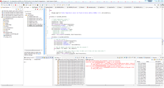
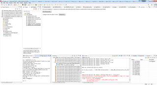
I have tried with EVM, in that if i follow the method-1 sequence then I am able to run all test successfully. Please note it.
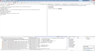
If i am missing any sequence, then please provide me the initialization sequence. I will try with that.
Please help me out.
--
Thanks & Regards,
Divyesh Patel
Hi Divyesh, every one of the methods you tried included executing the load_dmsc.js. Keep this out of the sequence. Just perform the following:
-power on board in No Boot mode
-connect to the board by going to the target configuration for your board and selecting Launch Selected Configuration
-connect to DMSC. Gel will run automatically to initialize PLL/PSC
-connect to Cortex_R5_0_0. Run GEL script Scripts -> AM64 DDR Initialization -> AM64_DDR_Initialization_ECC_Disabled
-run the read/write test
Regards,
James
Hi James,
PFA recording
Waiting for your feedback.
--
Thanks & Regards,
Divyesh Patel
Hi DIvyesh, thanks for the video. You appear to be doing everything as expected. We need to dig a little deeper. Can you send the results of Scripts->AM64 DDRSS DEbug -> Memory Debug -> AM64 DDRSS CTL PI PHY RegDump and AM64 DDRSS SS RegDump
Also can you share the DDR portion of your schematic?
REgards,
James
Hi James,
Thank you for your support.
PFA video and log
DMSC_Cortex_M3_0: GEL Output: Configuring ATCM for the R5Fs
DMSC_Cortex_M3_0: GEL Output: ATCM Configured.
DMSC_Cortex_M3_0: GEL Output: R5F Halt bits set.
DMSC_Cortex_M3_0: GEL Output: Configuring bootvectors
DMSC_Cortex_M3_0: GEL Output: Bootvectors configured.
DMSC_Cortex_M3_0: GEL Output: Running from DMSC
DMSC_Cortex_M3_0: GEL Output: Debugging enabled
DMSC_Cortex_M3_0: GEL Output: Programming all PLLs.
DMSC_Cortex_M3_0: GEL Output: Programming Main PLL 0 (Main PLL)
DMSC_Cortex_M3_0: GEL Output: Unlocked PLL MMRs.
DMSC_Cortex_M3_0: GEL Output: Read configuration MMRs.
DMSC_Cortex_M3_0: GEL Output: temp value (HSDIV_Presence) = 0x000003FF
DMSC_Cortex_M3_0: GEL Output: HSDIV presence value = 0x000003FF
DMSC_Cortex_M3_0: GEL Output: Number of hsidvs: 10
DMSC_Cortex_M3_0: GEL Output: Parsed PLL configuration information.
DMSC_Cortex_M3_0: GEL Output: Note: deskew PLL programming isn't implemented yet
DMSC_Cortex_M3_0: GEL Output: This is a fractional PLL, continuing on with normal programming.
DMSC_Cortex_M3_0: GEL Output: For debugging:
DMSC_Cortex_M3_0: GEL Output: Base address: 0x00680000
DMSC_Cortex_M3_0: GEL Output: PLL index: 0x00000000
DMSC_Cortex_M3_0: GEL Output: PLL index register base: 0x00000000
DMSC_Cortex_M3_0: GEL Output: Register: 0x00000020
DMSC_Cortex_M3_0: GEL Output: Clocking scheme: 1
DMSC_Cortex_M3_0: GEL Output: Set PLL to external bypass via Control MMR.
DMSC_Cortex_M3_0: GEL Output: Disabled PLL
DMSC_Cortex_M3_0: GEL Output: Enabled noise-cancelling DAC.
DMSC_Cortex_M3_0: GEL Output: Enabled the Delta-Sigma modulator.
DMSC_Cortex_M3_0: GEL Output: Programmed Reference clock pre-divider in output clock divider register.
DMSC_Cortex_M3_0: GEL Output: Programmed the integer feedback divider value in Freq Control 0 register.
DMSC_Cortex_M3_0: GEL Output: Fractional Divider Value is -1, don't set the fractional divider.
DMSC_Cortex_M3_0: GEL Output: Programmed the fractional feedback divider in Freq Control 0 register.
DMSC_Cortex_M3_0: GEL Output: Disabled the 4-phase clock generator (clk_4ph_en) in the control register.
DMSC_Cortex_M3_0: GEL Output: Enabled the FOUT4PHASE clocks in the control register.
DMSC_Cortex_M3_0: GEL Output: Set the first post-divider value (POSTDIV1) in the output divider control register.
DMSC_Cortex_M3_0: GEL Output: Set the second post-divider value (POSTDIV2) in the output divider control register.
DMSC_Cortex_M3_0: GEL Output: Programming HSDIV #0
DMSC_Cortex_M3_0: GEL Output: hsdiv_value: 3
DMSC_Cortex_M3_0: GEL Output: HSDIV reset asserted
DMSC_Cortex_M3_0: GEL Output: HSDIV divider value programmed.
DMSC_Cortex_M3_0: GEL Output: HSDIV reset de-asserted
DMSC_Cortex_M3_0: GEL Output: HSDIV #0 programmed.
DMSC_Cortex_M3_0: GEL Output: Programming HSDIV #1
DMSC_Cortex_M3_0: GEL Output: hsdiv_value: 9
DMSC_Cortex_M3_0: GEL Output: HSDIV reset asserted
DMSC_Cortex_M3_0: GEL Output: HSDIV divider value programmed.
DMSC_Cortex_M3_0: GEL Output: HSDIV reset de-asserted
DMSC_Cortex_M3_0: GEL Output: HSDIV #1 programmed.
DMSC_Cortex_M3_0: GEL Output: Programming HSDIV #2
DMSC_Cortex_M3_0: GEL Output: hsdiv_value: 24
DMSC_Cortex_M3_0: GEL Output: HSDIV reset asserted
DMSC_Cortex_M3_0: GEL Output: HSDIV divider value programmed.
DMSC_Cortex_M3_0: GEL Output: HSDIV reset de-asserted
DMSC_Cortex_M3_0: GEL Output: HSDIV #2 programmed.
DMSC_Cortex_M3_0: GEL Output: Programming HSDIV #3
DMSC_Cortex_M3_0: GEL Output: hsdiv_value: 14
DMSC_Cortex_M3_0: GEL Output: HSDIV reset asserted
DMSC_Cortex_M3_0: GEL Output: HSDIV divider value programmed.
DMSC_Cortex_M3_0: GEL Output: HSDIV reset de-asserted
DMSC_Cortex_M3_0: GEL Output: HSDIV #3 programmed.
DMSC_Cortex_M3_0: GEL Output: Programming HSDIV #4
DMSC_Cortex_M3_0: GEL Output: hsdiv_value: 7
DMSC_Cortex_M3_0: GEL Output: HSDIV reset asserted
DMSC_Cortex_M3_0: GEL Output: HSDIV divider value programmed.
DMSC_Cortex_M3_0: GEL Output: HSDIV reset de-asserted
DMSC_Cortex_M3_0: GEL Output: HSDIV #4 programmed.
DMSC_Cortex_M3_0: GEL Output: Programming HSDIV #5
DMSC_Cortex_M3_0: GEL Output: hsdiv_value: 4
DMSC_Cortex_M3_0: GEL Output: HSDIV reset asserted
DMSC_Cortex_M3_0: GEL Output: HSDIV divider value programmed.
DMSC_Cortex_M3_0: GEL Output: HSDIV reset de-asserted
DMSC_Cortex_M3_0: GEL Output: HSDIV #5 programmed.
DMSC_Cortex_M3_0: GEL Output: Programming HSDIV #6
DMSC_Cortex_M3_0: GEL Output: hsdiv_value: 3
DMSC_Cortex_M3_0: GEL Output: HSDIV reset asserted
DMSC_Cortex_M3_0: GEL Output: HSDIV divider value programmed.
DMSC_Cortex_M3_0: GEL Output: HSDIV reset de-asserted
DMSC_Cortex_M3_0: GEL Output: HSDIV #6 programmed.
DMSC_Cortex_M3_0: GEL Output: Programming HSDIV #7
DMSC_Cortex_M3_0: GEL Output: hsdiv_value: 3
DMSC_Cortex_M3_0: GEL Output: HSDIV reset asserted
DMSC_Cortex_M3_0: GEL Output: HSDIV divider value programmed.
DMSC_Cortex_M3_0: GEL Output: HSDIV reset de-asserted
DMSC_Cortex_M3_0: GEL Output: HSDIV #7 programmed.
DMSC_Cortex_M3_0: GEL Output: Programming HSDIV #8
DMSC_Cortex_M3_0: GEL Output: hsdiv_value: 7
DMSC_Cortex_M3_0: GEL Output: HSDIV reset asserted
DMSC_Cortex_M3_0: GEL Output: HSDIV divider value programmed.
DMSC_Cortex_M3_0: GEL Output: HSDIV reset de-asserted
DMSC_Cortex_M3_0: GEL Output: HSDIV #8 programmed.
DMSC_Cortex_M3_0: GEL Output: Programming HSDIV #9
DMSC_Cortex_M3_0: GEL Output: hsdiv_value: 2
DMSC_Cortex_M3_0: GEL Output: HSDIV reset asserted
DMSC_Cortex_M3_0: GEL Output: HSDIV divider value programmed.
DMSC_Cortex_M3_0: GEL Output: HSDIV reset de-asserted
DMSC_Cortex_M3_0: GEL Output: HSDIV #9 programmed.
DMSC_Cortex_M3_0: GEL Output: Selected Main Domain PLL Controller.
DMSC_Cortex_M3_0: GEL Output: Cleared bit 0 in the PLL controller control register.
DMSC_Cortex_M3_0: GEL Output: Cleared bit 5 in the PLL Controller control register.
DMSC_Cortex_M3_0: GEL Output: PLL controller is now in bypass mode.
DMSC_Cortex_M3_0: GEL Output: Set reset isolation to prevent a warm reset from killing the PLL controller.
DMSC_Cortex_M3_0: GEL Output: Set PLLDIV1 (output_div1).
DMSC_Cortex_M3_0: GEL Output: addr: 0x80410124 = 0x00008000
DMSC_Cortex_M3_0: GEL Output: Clear GOSET.
DMSC_Cortex_M3_0: GEL Output: GOSTAT is clear.
DMSC_Cortex_M3_0: GEL Output: Set PLLDIV1 (output_div1).
DMSC_Cortex_M3_0: GEL Output: Set ALN1.
DMSC_Cortex_M3_0: GEL Output: addr: 0x80410104 = 0x00000012
DMSC_Cortex_M3_0: GEL Output: Set OCSEL to 0x12, point C on the observation clock input tree inside the PLL Controller.
DMSC_Cortex_M3_0: GEL Output: addr: 0x80410148 = 0x00000002
DMSC_Cortex_M3_0: GEL Output: Set the clock control register to enable the OBSCLK output (bit 1).
DMSC_Cortex_M3_0: GEL Output: Set GOSET to 1.
DMSC_Cortex_M3_0: GEL Output: GOSTAT is clear.
DMSC_Cortex_M3_0: GEL Output: Enable PLL Controller (write to bit 0 in control register).
DMSC_Cortex_M3_0: GEL Output: Set GOSET to 0.
DMSC_Cortex_M3_0: GEL Output: PLLCTRL reset is cleared. PLLCTRL is free.
DMSC_Cortex_M3_0: GEL Output: Set the enable bit in the control register.
DMSC_Cortex_M3_0: GEL Output: PLL is locked.
DMSC_Cortex_M3_0: GEL Output: External bypass is disabled '0'. PLL and HSDIV clocks are engaging the rest of the SoC.
DMSC_Cortex_M3_0: GEL Output: Main PLL 0 (Main PLL) Set.
DMSC_Cortex_M3_0: GEL Output: Programming Main PLL 1 (Peripheral 0 PLL)
DMSC_Cortex_M3_0: GEL Output: Unlocked PLL MMRs.
DMSC_Cortex_M3_0: GEL Output: Read configuration MMRs.
DMSC_Cortex_M3_0: GEL Output: temp value (HSDIV_Presence) = 0x0000007F
DMSC_Cortex_M3_0: GEL Output: HSDIV presence value = 0x0000007F
DMSC_Cortex_M3_0: GEL Output: Number of hsidvs: 7
DMSC_Cortex_M3_0: GEL Output: Parsed PLL configuration information.
DMSC_Cortex_M3_0: GEL Output: Note: deskew PLL programming isn't implemented yet
DMSC_Cortex_M3_0: GEL Output: This is a fractional PLL, continuing on with normal programming.
DMSC_Cortex_M3_0: GEL Output: For debugging:
DMSC_Cortex_M3_0: GEL Output: Base address: 0x00680000
DMSC_Cortex_M3_0: GEL Output: PLL index: 0x00000001
DMSC_Cortex_M3_0: GEL Output: PLL index register base: 0x00001000
DMSC_Cortex_M3_0: GEL Output: Register: 0x00000020
DMSC_Cortex_M3_0: GEL Output: Clocking scheme: 1
DMSC_Cortex_M3_0: GEL Output: Set PLL to external bypass via Control MMR.
DMSC_Cortex_M3_0: GEL Output: Disabled PLL
DMSC_Cortex_M3_0: GEL Output: Enabled noise-cancelling DAC.
DMSC_Cortex_M3_0: GEL Output: Enabled the Delta-Sigma modulator.
DMSC_Cortex_M3_0: GEL Output: Programmed Reference clock pre-divider in output clock divider register.
DMSC_Cortex_M3_0: GEL Output: Programmed the integer feedback divider value in Freq Control 0 register.
DMSC_Cortex_M3_0: GEL Output: Fractional Divider Value is -1, don't set the fractional divider.
DMSC_Cortex_M3_0: GEL Output: Programmed the fractional feedback divider in Freq Control 0 register.
DMSC_Cortex_M3_0: GEL Output: Disabled the 4-phase clock generator (clk_4ph_en) in the control register.
DMSC_Cortex_M3_0: GEL Output: Enabled the FOUT4PHASE clocks in the control register.
DMSC_Cortex_M3_0: GEL Output: Set the first post-divider value (POSTDIV1) in the output divider control register.
DMSC_Cortex_M3_0: GEL Output: Set the second post-divider value (POSTDIV2) in the output divider control register.
DMSC_Cortex_M3_0: GEL Output: Programming HSDIV #0
DMSC_Cortex_M3_0: GEL Output: hsdiv_value: 9
DMSC_Cortex_M3_0: GEL Output: HSDIV reset asserted
DMSC_Cortex_M3_0: GEL Output: HSDIV divider value programmed.
DMSC_Cortex_M3_0: GEL Output: HSDIV reset de-asserted
DMSC_Cortex_M3_0: GEL Output: HSDIV #0 programmed.
DMSC_Cortex_M3_0: GEL Output: Programming HSDIV #1
DMSC_Cortex_M3_0: GEL Output: hsdiv_value: 11
DMSC_Cortex_M3_0: GEL Output: HSDIV reset asserted
DMSC_Cortex_M3_0: GEL Output: HSDIV divider value programmed.
DMSC_Cortex_M3_0: GEL Output: HSDIV reset de-asserted
DMSC_Cortex_M3_0: GEL Output: HSDIV #1 programmed.
DMSC_Cortex_M3_0: GEL Output: Programming HSDIV #2
DMSC_Cortex_M3_0: GEL Output: hsdiv_value: 4
DMSC_Cortex_M3_0: GEL Output: HSDIV reset asserted
DMSC_Cortex_M3_0: GEL Output: HSDIV divider value programmed.
DMSC_Cortex_M3_0: GEL Output: HSDIV reset de-asserted
DMSC_Cortex_M3_0: GEL Output: HSDIV #2 programmed.
DMSC_Cortex_M3_0: GEL Output: Programming HSDIV #3
DMSC_Cortex_M3_0: GEL Output: hsdiv_value: 9
DMSC_Cortex_M3_0: GEL Output: HSDIV reset asserted
DMSC_Cortex_M3_0: GEL Output: HSDIV divider value programmed.
DMSC_Cortex_M3_0: GEL Output: HSDIV reset de-asserted
DMSC_Cortex_M3_0: GEL Output: HSDIV #3 programmed.
DMSC_Cortex_M3_0: GEL Output: Programming HSDIV #4
DMSC_Cortex_M3_0: GEL Output: hsdiv_value: 79
DMSC_Cortex_M3_0: GEL Output: HSDIV reset asserted
DMSC_Cortex_M3_0: GEL Output: HSDIV divider value programmed.
DMSC_Cortex_M3_0: GEL Output: HSDIV reset de-asserted
DMSC_Cortex_M3_0: GEL Output: HSDIV #4 programmed.
DMSC_Cortex_M3_0: GEL Output: Programming HSDIV #5
DMSC_Cortex_M3_0: GEL Output: hsdiv_value: 5
DMSC_Cortex_M3_0: GEL Output: HSDIV reset asserted
DMSC_Cortex_M3_0: GEL Output: HSDIV divider value programmed.
DMSC_Cortex_M3_0: GEL Output: HSDIV reset de-asserted
DMSC_Cortex_M3_0: GEL Output: HSDIV #5 programmed.
DMSC_Cortex_M3_0: GEL Output: Programming HSDIV #6
DMSC_Cortex_M3_0: GEL Output: hsdiv_value: 15
DMSC_Cortex_M3_0: GEL Output: HSDIV reset asserted
DMSC_Cortex_M3_0: GEL Output: HSDIV divider value programmed.
DMSC_Cortex_M3_0: GEL Output: HSDIV reset de-asserted
DMSC_Cortex_M3_0: GEL Output: HSDIV #6 programmed.
DMSC_Cortex_M3_0: GEL Output: Set the enable bit in the control register.
DMSC_Cortex_M3_0: GEL Output: PLL is locked.
DMSC_Cortex_M3_0: GEL Output: External bypass is disabled '0'. PLL and HSDIV clocks are engaging the rest of the SoC.
DMSC_Cortex_M3_0: GEL Output: Main PLL 1 (Peripheral 0 PLL) Set.
DMSC_Cortex_M3_0: GEL Output: Programming Main PLL 2 (Peripheral 1 PLL)
DMSC_Cortex_M3_0: GEL Output: Unlocked PLL MMRs.
DMSC_Cortex_M3_0: GEL Output: Read configuration MMRs.
DMSC_Cortex_M3_0: GEL Output: temp value (HSDIV_Presence) = 0x000003FF
DMSC_Cortex_M3_0: GEL Output: HSDIV presence value = 0x000003FF
DMSC_Cortex_M3_0: GEL Output: Number of hsidvs: 10
DMSC_Cortex_M3_0: GEL Output: Parsed PLL configuration information.
DMSC_Cortex_M3_0: GEL Output: Note: deskew PLL programming isn't implemented yet
DMSC_Cortex_M3_0: GEL Output: This is a fractional PLL, continuing on with normal programming.
DMSC_Cortex_M3_0: GEL Output: For debugging:
DMSC_Cortex_M3_0: GEL Output: Base address: 0x00680000
DMSC_Cortex_M3_0: GEL Output: PLL index: 0x00000002
DMSC_Cortex_M3_0: GEL Output: PLL index register base: 0x00002000
DMSC_Cortex_M3_0: GEL Output: Register: 0x00000020
DMSC_Cortex_M3_0: GEL Output: Clocking scheme: 1
DMSC_Cortex_M3_0: GEL Output: Set PLL to external bypass via Control MMR.
DMSC_Cortex_M3_0: GEL Output: Disabled PLL
DMSC_Cortex_M3_0: GEL Output: Enabled noise-cancelling DAC.
DMSC_Cortex_M3_0: GEL Output: Enabled the Delta-Sigma modulator.
DMSC_Cortex_M3_0: GEL Output: Programmed Reference clock pre-divider in output clock divider register.
DMSC_Cortex_M3_0: GEL Output: Programmed the integer feedback divider value in Freq Control 0 register.
DMSC_Cortex_M3_0: GEL Output: Fractional Divider Value is -1, don't set the fractional divider.
DMSC_Cortex_M3_0: GEL Output: Programmed the fractional feedback divider in Freq Control 0 register.
DMSC_Cortex_M3_0: GEL Output: Disabled the 4-phase clock generator (clk_4ph_en) in the control register.
DMSC_Cortex_M3_0: GEL Output: Enabled the FOUT4PHASE clocks in the control register.
DMSC_Cortex_M3_0: GEL Output: Set the first post-divider value (POSTDIV1) in the output divider control register.
DMSC_Cortex_M3_0: GEL Output: Set the second post-divider value (POSTDIV2) in the output divider control register.
DMSC_Cortex_M3_0: GEL Output: Programming HSDIV #0
DMSC_Cortex_M3_0: GEL Output: hsdiv_value: 5
DMSC_Cortex_M3_0: GEL Output: HSDIV reset asserted
DMSC_Cortex_M3_0: GEL Output: HSDIV divider value programmed.
DMSC_Cortex_M3_0: GEL Output: HSDIV reset de-asserted
DMSC_Cortex_M3_0: GEL Output: HSDIV #0 programmed.
DMSC_Cortex_M3_0: GEL Output: Programming HSDIV #1
DMSC_Cortex_M3_0: GEL Output: i: 1, HSDIV value is -1, don't program this one
DMSC_Cortex_M3_0: GEL Output: HSDIV clock output disabled.
DMSC_Cortex_M3_0: GEL Output: HSDIV #1 programmed.
DMSC_Cortex_M3_0: GEL Output: Programming HSDIV #2
DMSC_Cortex_M3_0: GEL Output: hsdiv_value: 8
DMSC_Cortex_M3_0: GEL Output: HSDIV reset asserted
DMSC_Cortex_M3_0: GEL Output: HSDIV divider value programmed.
DMSC_Cortex_M3_0: GEL Output: HSDIV reset de-asserted
DMSC_Cortex_M3_0: GEL Output: HSDIV #2 programmed.
DMSC_Cortex_M3_0: GEL Output: Programming HSDIV #3
DMSC_Cortex_M3_0: GEL Output: hsdiv_value: 5
DMSC_Cortex_M3_0: GEL Output: HSDIV reset asserted
DMSC_Cortex_M3_0: GEL Output: HSDIV divider value programmed.
DMSC_Cortex_M3_0: GEL Output: HSDIV reset de-asserted
DMSC_Cortex_M3_0: GEL Output: HSDIV #3 programmed.
DMSC_Cortex_M3_0: GEL Output: Programming HSDIV #4
DMSC_Cortex_M3_0: GEL Output: hsdiv_value: 17
DMSC_Cortex_M3_0: GEL Output: HSDIV reset asserted
DMSC_Cortex_M3_0: GEL Output: HSDIV divider value programmed.
DMSC_Cortex_M3_0: GEL Output: HSDIV reset de-asserted
DMSC_Cortex_M3_0: GEL Output: HSDIV #4 programmed.
DMSC_Cortex_M3_0: GEL Output: Programming HSDIV #5
DMSC_Cortex_M3_0: GEL Output: hsdiv_value: 7
DMSC_Cortex_M3_0: GEL Output: HSDIV reset asserted
DMSC_Cortex_M3_0: GEL Output: HSDIV divider value programmed.
DMSC_Cortex_M3_0: GEL Output: HSDIV reset de-asserted
DMSC_Cortex_M3_0: GEL Output: HSDIV #5 programmed.
DMSC_Cortex_M3_0: GEL Output: Programming HSDIV #6
DMSC_Cortex_M3_0: GEL Output: hsdiv_value: 7
DMSC_Cortex_M3_0: GEL Output: HSDIV reset asserted
DMSC_Cortex_M3_0: GEL Output: HSDIV divider value programmed.
DMSC_Cortex_M3_0: GEL Output: HSDIV reset de-asserted
DMSC_Cortex_M3_0: GEL Output: HSDIV #6 programmed.
DMSC_Cortex_M3_0: GEL Output: Programming HSDIV #7
DMSC_Cortex_M3_0: GEL Output: hsdiv_value: 17
DMSC_Cortex_M3_0: GEL Output: HSDIV reset asserted
DMSC_Cortex_M3_0: GEL Output: HSDIV divider value programmed.
DMSC_Cortex_M3_0: GEL Output: HSDIV reset de-asserted
DMSC_Cortex_M3_0: GEL Output: HSDIV #7 programmed.
DMSC_Cortex_M3_0: GEL Output: Programming HSDIV #8
DMSC_Cortex_M3_0: GEL Output: i: 8, HSDIV value is -1, don't program this one
DMSC_Cortex_M3_0: GEL Output: HSDIV clock output disabled.
DMSC_Cortex_M3_0: GEL Output: HSDIV #8 programmed.
DMSC_Cortex_M3_0: GEL Output: Programming HSDIV #9
DMSC_Cortex_M3_0: GEL Output: hsdiv_value: 4
DMSC_Cortex_M3_0: GEL Output: HSDIV reset asserted
DMSC_Cortex_M3_0: GEL Output: HSDIV divider value programmed.
DMSC_Cortex_M3_0: GEL Output: HSDIV reset de-asserted
DMSC_Cortex_M3_0: GEL Output: HSDIV #9 programmed.
DMSC_Cortex_M3_0: GEL Output: Set the enable bit in the control register.
DMSC_Cortex_M3_0: GEL Output: PLL is locked.
DMSC_Cortex_M3_0: GEL Output: External bypass is disabled '0'. PLL and HSDIV clocks are engaging the rest of the SoC.
DMSC_Cortex_M3_0: GEL Output: Main PLL 2 (Peripheral 1 PLL) Set.
DMSC_Cortex_M3_0: GEL Output: Programming Main PLL 8 (ARM0 PLL)
DMSC_Cortex_M3_0: GEL Output: Unlocked PLL MMRs.
DMSC_Cortex_M3_0: GEL Output: Read configuration MMRs.
DMSC_Cortex_M3_0: GEL Output: temp value (HSDIV_Presence) = 0x00000001
DMSC_Cortex_M3_0: GEL Output: HSDIV presence value = 0x00000001
DMSC_Cortex_M3_0: GEL Output: Number of hsidvs: 1
DMSC_Cortex_M3_0: GEL Output: Parsed PLL configuration information.
DMSC_Cortex_M3_0: GEL Output: Note: deskew PLL programming isn't implemented yet
DMSC_Cortex_M3_0: GEL Output: This is a fractional PLL, continuing on with normal programming.
DMSC_Cortex_M3_0: GEL Output: For debugging:
DMSC_Cortex_M3_0: GEL Output: Base address: 0x00680000
DMSC_Cortex_M3_0: GEL Output: PLL index: 0x00000008
DMSC_Cortex_M3_0: GEL Output: PLL index register base: 0x00008000
DMSC_Cortex_M3_0: GEL Output: Register: 0x00000020
DMSC_Cortex_M3_0: GEL Output: Clocking scheme: 1
DMSC_Cortex_M3_0: GEL Output: Set PLL to external bypass via Control MMR.
DMSC_Cortex_M3_0: GEL Output: Disabled PLL
DMSC_Cortex_M3_0: GEL Output: Enabled noise-cancelling DAC.
DMSC_Cortex_M3_0: GEL Output: Enabled the Delta-Sigma modulator.
DMSC_Cortex_M3_0: GEL Output: Programmed Reference clock pre-divider in output clock divider register.
DMSC_Cortex_M3_0: GEL Output: Programmed the integer feedback divider value in Freq Control 0 register.
DMSC_Cortex_M3_0: GEL Output: Fractional Divider Value is -1, don't set the fractional divider.
DMSC_Cortex_M3_0: GEL Output: Programmed the fractional feedback divider in Freq Control 0 register.
DMSC_Cortex_M3_0: GEL Output: Disabled the 4-phase clock generator (clk_4ph_en) in the control register.
DMSC_Cortex_M3_0: GEL Output: Enabled the FOUT4PHASE clocks in the control register.
DMSC_Cortex_M3_0: GEL Output: Set the first post-divider value (POSTDIV1) in the output divider control register.
DMSC_Cortex_M3_0: GEL Output: Set the second post-divider value (POSTDIV2) in the output divider control register.
DMSC_Cortex_M3_0: GEL Output: Programming HSDIV #0
DMSC_Cortex_M3_0: GEL Output: hsdiv_value: 1
DMSC_Cortex_M3_0: GEL Output: HSDIV reset asserted
DMSC_Cortex_M3_0: GEL Output: HSDIV divider value programmed.
DMSC_Cortex_M3_0: GEL Output: HSDIV reset de-asserted
DMSC_Cortex_M3_0: GEL Output: HSDIV #0 programmed.
DMSC_Cortex_M3_0: GEL Output: Set the enable bit in the control register.
DMSC_Cortex_M3_0: GEL Output: PLL is locked.
DMSC_Cortex_M3_0: GEL Output: External bypass is disabled '0'. PLL and HSDIV clocks are engaging the rest of the SoC.
DMSC_Cortex_M3_0: GEL Output: Main PLL 8 (ARM0 PLL) Set.
DMSC_Cortex_M3_0: GEL Output: Programming Main PLL 12 (DDR PLL)
DMSC_Cortex_M3_0: GEL Output: Unlocked PLL MMRs.
DMSC_Cortex_M3_0: GEL Output: Read configuration MMRs.
DMSC_Cortex_M3_0: GEL Output: temp value (HSDIV_Presence) = 0x00000001
DMSC_Cortex_M3_0: GEL Output: HSDIV presence value = 0x00000001
DMSC_Cortex_M3_0: GEL Output: Number of hsidvs: 1
DMSC_Cortex_M3_0: GEL Output: Parsed PLL configuration information.
DMSC_Cortex_M3_0: GEL Output: Note: deskew PLL programming isn't implemented yet
DMSC_Cortex_M3_0: GEL Output: This is a fractional PLL, continuing on with normal programming.
DMSC_Cortex_M3_0: GEL Output: For debugging:
DMSC_Cortex_M3_0: GEL Output: Base address: 0x00680000
DMSC_Cortex_M3_0: GEL Output: PLL index: 0x0000000C
DMSC_Cortex_M3_0: GEL Output: PLL index register base: 0x0000C000
DMSC_Cortex_M3_0: GEL Output: Register: 0x00000020
DMSC_Cortex_M3_0: GEL Output: Clocking scheme: 1
DMSC_Cortex_M3_0: GEL Output: Set PLL to external bypass via Control MMR.
DMSC_Cortex_M3_0: GEL Output: Disabled PLL
DMSC_Cortex_M3_0: GEL Output: Enabled noise-cancelling DAC.
DMSC_Cortex_M3_0: GEL Output: Enabled the Delta-Sigma modulator.
DMSC_Cortex_M3_0: GEL Output: Programmed Reference clock pre-divider in output clock divider register.
DMSC_Cortex_M3_0: GEL Output: Programmed the integer feedback divider value in Freq Control 0 register.
DMSC_Cortex_M3_0: GEL Output: Fractional Divider Value is -1, don't set the fractional divider.
DMSC_Cortex_M3_0: GEL Output: Programmed the fractional feedback divider in Freq Control 0 register.
DMSC_Cortex_M3_0: GEL Output: Disabled the 4-phase clock generator (clk_4ph_en) in the control register.
DMSC_Cortex_M3_0: GEL Output: Enabled the FOUT4PHASE clocks in the control register.
DMSC_Cortex_M3_0: GEL Output: Set the first post-divider value (POSTDIV1) in the output divider control register.
DMSC_Cortex_M3_0: GEL Output: Set the second post-divider value (POSTDIV2) in the output divider control register.
DMSC_Cortex_M3_0: GEL Output: Programming HSDIV #0
DMSC_Cortex_M3_0: GEL Output: hsdiv_value: 3
DMSC_Cortex_M3_0: GEL Output: HSDIV reset asserted
DMSC_Cortex_M3_0: GEL Output: HSDIV divider value programmed.
DMSC_Cortex_M3_0: GEL Output: HSDIV reset de-asserted
DMSC_Cortex_M3_0: GEL Output: HSDIV #0 programmed.
DMSC_Cortex_M3_0: GEL Output: Set the enable bit in the control register.
DMSC_Cortex_M3_0: GEL Output: PLL is locked.
DMSC_Cortex_M3_0: GEL Output: External bypass is disabled '0'. PLL and HSDIV clocks are engaging the rest of the SoC.
DMSC_Cortex_M3_0: GEL Output: Main PLL 12 (DDR PLL) Set.
DMSC_Cortex_M3_0: GEL Output: Programming Main PLL 14 (Main Domain Pulsar) PLL)
DMSC_Cortex_M3_0: GEL Output: Unlocked PLL MMRs.
DMSC_Cortex_M3_0: GEL Output: Read configuration MMRs.
DMSC_Cortex_M3_0: GEL Output: temp value (HSDIV_Presence) = 0x00000003
DMSC_Cortex_M3_0: GEL Output: HSDIV presence value = 0x00000003
DMSC_Cortex_M3_0: GEL Output: Number of hsidvs: 2
DMSC_Cortex_M3_0: GEL Output: Parsed PLL configuration information.
DMSC_Cortex_M3_0: GEL Output: Note: deskew PLL programming isn't implemented yet
DMSC_Cortex_M3_0: GEL Output: This is a fractional PLL, continuing on with normal programming.
DMSC_Cortex_M3_0: GEL Output: For debugging:
DMSC_Cortex_M3_0: GEL Output: Base address: 0x00680000
DMSC_Cortex_M3_0: GEL Output: PLL index: 0x0000000E
DMSC_Cortex_M3_0: GEL Output: PLL index register base: 0x0000E000
DMSC_Cortex_M3_0: GEL Output: Register: 0x00000020
DMSC_Cortex_M3_0: GEL Output: Clocking scheme: 1
DMSC_Cortex_M3_0: GEL Output: Set PLL to external bypass via Control MMR.
DMSC_Cortex_M3_0: GEL Output: Disabled PLL
DMSC_Cortex_M3_0: GEL Output: Enabled noise-cancelling DAC.
DMSC_Cortex_M3_0: GEL Output: Enabled the Delta-Sigma modulator.
DMSC_Cortex_M3_0: GEL Output: Programmed Reference clock pre-divider in output clock divider register.
DMSC_Cortex_M3_0: GEL Output: Programmed the integer feedback divider value in Freq Control 0 register.
DMSC_Cortex_M3_0: GEL Output: Fractional Divider Value is -1, don't set the fractional divider.
DMSC_Cortex_M3_0: GEL Output: Programmed the fractional feedback divider in Freq Control 0 register.
DMSC_Cortex_M3_0: GEL Output: Disabled the 4-phase clock generator (clk_4ph_en) in the control register.
DMSC_Cortex_M3_0: GEL Output: Enabled the FOUT4PHASE clocks in the control register.
DMSC_Cortex_M3_0: GEL Output: Set the first post-divider value (POSTDIV1) in the output divider control register.
DMSC_Cortex_M3_0: GEL Output: Set the second post-divider value (POSTDIV2) in the output divider control register.
DMSC_Cortex_M3_0: GEL Output: Programming HSDIV #0
DMSC_Cortex_M3_0: GEL Output: hsdiv_value: 2
DMSC_Cortex_M3_0: GEL Output: HSDIV reset asserted
DMSC_Cortex_M3_0: GEL Output: HSDIV divider value programmed.
DMSC_Cortex_M3_0: GEL Output: HSDIV reset de-asserted
DMSC_Cortex_M3_0: GEL Output: HSDIV #0 programmed.
DMSC_Cortex_M3_0: GEL Output: Programming HSDIV #1
DMSC_Cortex_M3_0: GEL Output: hsdiv_value: 2
DMSC_Cortex_M3_0: GEL Output: HSDIV reset asserted
DMSC_Cortex_M3_0: GEL Output: HSDIV divider value programmed.
DMSC_Cortex_M3_0: GEL Output: HSDIV reset de-asserted
DMSC_Cortex_M3_0: GEL Output: HSDIV #1 programmed.
DMSC_Cortex_M3_0: GEL Output: Set the enable bit in the control register.
DMSC_Cortex_M3_0: GEL Output: PLL is locked.
DMSC_Cortex_M3_0: GEL Output: External bypass is disabled '0'. PLL and HSDIV clocks are engaging the rest of the SoC.
DMSC_Cortex_M3_0: GEL Output: Main PLL 14 (Main Domain Pulsar PLL) Set.
DMSC_Cortex_M3_0: GEL Output: Programming MCU PLL 0 (MCU PLL)
DMSC_Cortex_M3_0: GEL Output: Unlocked PLL MMRs.
DMSC_Cortex_M3_0: GEL Output: Read configuration MMRs.
DMSC_Cortex_M3_0: GEL Output: temp value (HSDIV_Presence) = 0x0000001F
DMSC_Cortex_M3_0: GEL Output: HSDIV presence value = 0x0000001F
DMSC_Cortex_M3_0: GEL Output: Number of hsidvs: 5
DMSC_Cortex_M3_0: GEL Output: Parsed PLL configuration information.
DMSC_Cortex_M3_0: GEL Output: Note: deskew PLL programming isn't implemented yet
DMSC_Cortex_M3_0: GEL Output: This is a fractional PLL, continuing on with normal programming.
DMSC_Cortex_M3_0: GEL Output: For debugging:
DMSC_Cortex_M3_0: GEL Output: Base address: 0x04040000
DMSC_Cortex_M3_0: GEL Output: PLL index: 0x00000000
DMSC_Cortex_M3_0: GEL Output: PLL index register base: 0x00000000
DMSC_Cortex_M3_0: GEL Output: Register: 0x00000020
DMSC_Cortex_M3_0: GEL Output: Clocking scheme: 1
DMSC_Cortex_M3_0: GEL Output: Set PLL to external bypass via Control MMR.
DMSC_Cortex_M3_0: GEL Output: Disabled PLL
DMSC_Cortex_M3_0: GEL Output: Enabled noise-cancelling DAC.
DMSC_Cortex_M3_0: GEL Output: Enabled the Delta-Sigma modulator.
DMSC_Cortex_M3_0: GEL Output: Programmed Reference clock pre-divider in output clock divider register.
DMSC_Cortex_M3_0: GEL Output: Programmed the integer feedback divider value in Freq Control 0 register.
DMSC_Cortex_M3_0: GEL Output: Fractional Divider Value is -1, don't set the fractional divider.
DMSC_Cortex_M3_0: GEL Output: Programmed the fractional feedback divider in Freq Control 0 register.
DMSC_Cortex_M3_0: GEL Output: Disabled the 4-phase clock generator (clk_4ph_en) in the control register.
DMSC_Cortex_M3_0: GEL Output: Enabled the FOUT4PHASE clocks in the control register.
DMSC_Cortex_M3_0: GEL Output: Set the first post-divider value (POSTDIV1) in the output divider control register.
DMSC_Cortex_M3_0: GEL Output: Set the second post-divider value (POSTDIV2) in the output divider control register.
DMSC_Cortex_M3_0: GEL Output: Programming HSDIV #0
DMSC_Cortex_M3_0: GEL Output: hsdiv_value: 5
DMSC_Cortex_M3_0: GEL Output: HSDIV reset asserted
DMSC_Cortex_M3_0: GEL Output: HSDIV divider value programmed.
DMSC_Cortex_M3_0: GEL Output: HSDIV reset de-asserted
DMSC_Cortex_M3_0: GEL Output: HSDIV #0 programmed.
DMSC_Cortex_M3_0: GEL Output: Programming HSDIV #1
DMSC_Cortex_M3_0: GEL Output: hsdiv_value: 24
DMSC_Cortex_M3_0: GEL Output: HSDIV reset asserted
DMSC_Cortex_M3_0: GEL Output: HSDIV divider value programmed.
DMSC_Cortex_M3_0: GEL Output: HSDIV reset de-asserted
DMSC_Cortex_M3_0: GEL Output: HSDIV #1 programmed.
DMSC_Cortex_M3_0: GEL Output: Programming HSDIV #2
DMSC_Cortex_M3_0: GEL Output: hsdiv_value: 24
DMSC_Cortex_M3_0: GEL Output: HSDIV reset asserted
DMSC_Cortex_M3_0: GEL Output: HSDIV divider value programmed.
DMSC_Cortex_M3_0: GEL Output: HSDIV reset de-asserted
DMSC_Cortex_M3_0: GEL Output: HSDIV #2 programmed.
DMSC_Cortex_M3_0: GEL Output: Programming HSDIV #3
DMSC_Cortex_M3_0: GEL Output: hsdiv_value: 11
DMSC_Cortex_M3_0: GEL Output: HSDIV reset asserted
DMSC_Cortex_M3_0: GEL Output: HSDIV divider value programmed.
DMSC_Cortex_M3_0: GEL Output: HSDIV reset de-asserted
DMSC_Cortex_M3_0: GEL Output: HSDIV #3 programmed.
DMSC_Cortex_M3_0: GEL Output: Programming HSDIV #4
DMSC_Cortex_M3_0: GEL Output: hsdiv_value: 11
DMSC_Cortex_M3_0: GEL Output: HSDIV reset asserted
DMSC_Cortex_M3_0: GEL Output: HSDIV divider value programmed.
DMSC_Cortex_M3_0: GEL Output: HSDIV reset de-asserted
DMSC_Cortex_M3_0: GEL Output: HSDIV #4 programmed.
DMSC_Cortex_M3_0: GEL Output: Selected MCU Domain PLL Conntroller.
DMSC_Cortex_M3_0: GEL Output: Cleared bit 0 in the PLL controller control register.
DMSC_Cortex_M3_0: GEL Output: Cleared bit 5 in the PLL Controller control register.
DMSC_Cortex_M3_0: GEL Output: PLL controller is now in bypass mode.
DMSC_Cortex_M3_0: GEL Output: Set reset isolation to prevent a warm reset from killing the PLL controller.
DMSC_Cortex_M3_0: GEL Output: Set PLLDIV1 (output_div1).
DMSC_Cortex_M3_0: GEL Output: addr: 0x84020124 = 0x00008000
DMSC_Cortex_M3_0: GEL Output: Clear GOSET.
DMSC_Cortex_M3_0: GEL Output: GOSTAT is clear.
DMSC_Cortex_M3_0: GEL Output: Set PLLDIV1 (output_div1).
DMSC_Cortex_M3_0: GEL Output: Set ALN1.
DMSC_Cortex_M3_0: GEL Output: addr: 0x84020104 = 0x00000012
DMSC_Cortex_M3_0: GEL Output: Set OCSEL to 0x12, point C on the observation clock input tree inside the PLL Controller.
DMSC_Cortex_M3_0: GEL Output: addr: 0x84020148 = 0x00000002
DMSC_Cortex_M3_0: GEL Output: Set the clock control register to enable the OBSCLK output (bit 1).
DMSC_Cortex_M3_0: GEL Output: Set GOSET to 1.
DMSC_Cortex_M3_0: GEL Output: GOSTAT is clear.
DMSC_Cortex_M3_0: GEL Output: Enable PLL Controller (write to bit 0 in control register).
DMSC_Cortex_M3_0: GEL Output: Set GOSET to 0.
DMSC_Cortex_M3_0: GEL Output: PLLCTRL reset is cleared. PLLCTRL is free.
DMSC_Cortex_M3_0: GEL Output: Set the enable bit in the control register.
DMSC_Cortex_M3_0: GEL Output: PLL is locked.
DMSC_Cortex_M3_0: GEL Output: External bypass is disabled '0'. PLL and HSDIV clocks are engaging the rest of the SoC.
DMSC_Cortex_M3_0: GEL Output: MCU PLL 0 (MCU PLL) Set.
DMSC_Cortex_M3_0: GEL Output: All PLLs programmed.
DMSC_Cortex_M3_0: GEL Output: Powering up all PSC power domains in progress...
DMSC_Cortex_M3_0: GEL Output: Powering up MAIN domain peripherals...
DMSC_Cortex_M3_0: GEL Output: Powering up GP_CORE_CTL.
DMSC_Cortex_M3_0: GEL Output: Powering up LPSC_DMSC
DMSC_Cortex_M3_0: GEL Output: Running from DMSC
DMSC_Cortex_M3_0: GEL Output: No change needed.
DMSC_Cortex_M3_0: GEL Output: Powering up LPSC_MAIN_TEST
DMSC_Cortex_M3_0: GEL Output: Running from DMSC
DMSC_Cortex_M3_0: GEL Output: No change needed.
DMSC_Cortex_M3_0: GEL Output: Powering up LPSC_MAIN_PBIST
DMSC_Cortex_M3_0: GEL Output: Running from DMSC
DMSC_Cortex_M3_0: GEL Output: No change needed.
DMSC_Cortex_M3_0: GEL Output: Powering up LPSC_EMMC_4B
DMSC_Cortex_M3_0: GEL Output: Running from DMSC
DMSC_Cortex_M3_0: GEL Output: No change needed.
DMSC_Cortex_M3_0: GEL Output: Powering up LPSC_EMMC_8B
DMSC_Cortex_M3_0: GEL Output: Running from DMSC
DMSC_Cortex_M3_0: GEL Output: No change needed.
DMSC_Cortex_M3_0: GEL Output: Powering up LPSC_USB
DMSC_Cortex_M3_0: GEL Output: Running from DMSC
DMSC_Cortex_M3_0: GEL Output: No change needed.
DMSC_Cortex_M3_0: GEL Output: Powering up LPSC_ADC
DMSC_Cortex_M3_0: GEL Output: Running from DMSC
DMSC_Cortex_M3_0: GEL Output: No change needed.
DMSC_Cortex_M3_0: GEL Output: Powering up LPSC_DEBUGSS
DMSC_Cortex_M3_0: GEL Output: Running from DMSC
DMSC_Cortex_M3_0: GEL Output: No change needed.
DMSC_Cortex_M3_0: GEL Output: Powering up LPSC_GPMC
DMSC_Cortex_M3_0: GEL Output: Running from DMSC
DMSC_Cortex_M3_0: GEL Output: No change needed.
DMSC_Cortex_M3_0: GEL Output: Powering up LPSC_EMIF_CFG
DMSC_Cortex_M3_0: GEL Output: Running from DMSC
DMSC_Cortex_M3_0: GEL Output: No change needed.
DMSC_Cortex_M3_0: GEL Output: Powering up LPSC_EMIF_DATA
DMSC_Cortex_M3_0: GEL Output: Running from DMSC
DMSC_Cortex_M3_0: GEL Output: No change needed.
DMSC_Cortex_M3_0: GEL Output: Powering up LPSC_MCAN_0
DMSC_Cortex_M3_0: GEL Output: Running from DMSC
DMSC_Cortex_M3_0: GEL Output: No change needed.
DMSC_Cortex_M3_0: GEL Output: Powering up LPSC_MCAN_1
DMSC_Cortex_M3_0: GEL Output: Running from DMSC
DMSC_Cortex_M3_0: GEL Output: No change needed.
DMSC_Cortex_M3_0: GEL Output: Powering up LPSC_SA2UL
DMSC_Cortex_M3_0: GEL Output: Running from DMSC
DMSC_Cortex_M3_0: GEL Output: No change needed.
DMSC_Cortex_M3_0: GEL Output: Powering up LPSC_SERDES_0
DMSC_Cortex_M3_0: GEL Output: Running from DMSC
DMSC_Cortex_M3_0: GEL Output: No change needed.
DMSC_Cortex_M3_0: GEL Output: Powering up LPSC_PCIE_0
DMSC_Cortex_M3_0: GEL Output: Running from DMSC
DMSC_Cortex_M3_0: GEL Output: No change needed.
DMSC_Cortex_M3_0: GEL Output: Powering up GP_CORE_CTL done.
DMSC_Cortex_M3_0: GEL Output: Powering up PD_A53_CLUSTER_0.
DMSC_Cortex_M3_0: GEL Output: Powering up LPSC_A53_CLUSTER_0
DMSC_Cortex_M3_0: GEL Output: Running from DMSC
DMSC_Cortex_M3_0: GEL Output: ERROR: module state NOT changed!
DMSC_Cortex_M3_0: GEL Output: Powering up LPSC_A53_CLUSTER_0_PBIST
DMSC_Cortex_M3_0: GEL Output: Running from DMSC
DMSC_Cortex_M3_0: GEL Output: No change needed.
DMSC_Cortex_M3_0: GEL Output: Powering up PD_A53_CLUSTER_0 done.
DMSC_Cortex_M3_0: GEL Output: Powering up PD_A53_0.
DMSC_Cortex_M3_0: GEL Output: Powering up LPSC_A53_0
DMSC_Cortex_M3_0: GEL Output: Running from DMSC
DMSC_Cortex_M3_0: GEL Output: ERROR: module state NOT changed!
DMSC_Cortex_M3_0: GEL Output: Powering up PD_A53_0 done.
DMSC_Cortex_M3_0: GEL Output: Powering up PD_A53_1.
DMSC_Cortex_M3_0: GEL Output: Powering up LPSC_A53_1
DMSC_Cortex_M3_0: GEL Output: Running from DMSC
DMSC_Cortex_M3_0: GEL Output: ERROR: module state NOT changed!
DMSC_Cortex_M3_0: GEL Output: Powering up PD_A53_1 done.
DMSC_Cortex_M3_0: GEL Output: Powering up PD_PULSAR_0.
DMSC_Cortex_M3_0: GEL Output: Powering up LPSC_PULSAR_0_R5_0
DMSC_Cortex_M3_0: GEL Output: Running from DMSC
DMSC_Cortex_M3_0: GEL Output: No change needed.
DMSC_Cortex_M3_0: GEL Output: Powering up LPSC_PULSAR_0_R5_1
DMSC_Cortex_M3_0: GEL Output: Running from DMSC
DMSC_Cortex_M3_0: GEL Output: No change needed.
DMSC_Cortex_M3_0: GEL Output: Powering up LPSC_PULSAR_PBIST_0
DMSC_Cortex_M3_0: GEL Output: Running from DMSC
DMSC_Cortex_M3_0: GEL Output: No change needed.
DMSC_Cortex_M3_0: GEL Output: Powering up PD_PULSAR_0 done.
DMSC_Cortex_M3_0: GEL Output: Powering up PD_PULSAR_1.
DMSC_Cortex_M3_0: GEL Output: Powering up LPSC_PULSAR_1_R5_0
DMSC_Cortex_M3_0: GEL Output: Running from DMSC
DMSC_Cortex_M3_0: GEL Output: No change needed.
DMSC_Cortex_M3_0: GEL Output: Powering up LPSC_PULSAR_1_R5_1
DMSC_Cortex_M3_0: GEL Output: Running from DMSC
DMSC_Cortex_M3_0: GEL Output: No change needed.
DMSC_Cortex_M3_0: GEL Output: Powering up LPSC_PULSAR_PBIST_1
DMSC_Cortex_M3_0: GEL Output: Running from DMSC
DMSC_Cortex_M3_0: GEL Output: No change needed.
DMSC_Cortex_M3_0: GEL Output: Powering up PD_PULSAR_1 done.
DMSC_Cortex_M3_0: GEL Output: Powering up PD_ICSSG_0.
DMSC_Cortex_M3_0: GEL Output: Powering up LPSC_ICSSG_0
DMSC_Cortex_M3_0: GEL Output: Running from DMSC
DMSC_Cortex_M3_0: GEL Output: No change needed.
DMSC_Cortex_M3_0: GEL Output: Powering up PD_ICSSG_0 done.
DMSC_Cortex_M3_0: GEL Output: Powering up PD_ICSSG_1.
DMSC_Cortex_M3_0: GEL Output: Powering up LPSC_ICSSG_1
DMSC_Cortex_M3_0: GEL Output: Running from DMSC
DMSC_Cortex_M3_0: GEL Output: No change needed.
DMSC_Cortex_M3_0: GEL Output: Powering up PD_ICSSG_1 done.
DMSC_Cortex_M3_0: GEL Output: Powering up PD_CPSW.
DMSC_Cortex_M3_0: GEL Output: Powering up LPSC_CPSW3G
DMSC_Cortex_M3_0: GEL Output: Running from DMSC
DMSC_Cortex_M3_0: GEL Output: No change needed.
DMSC_Cortex_M3_0: GEL Output: Powering up PD_CPSW done.
DMSC_Cortex_M3_0: GEL Output: Powering up all MAIN domain peripherals done.
DMSC_Cortex_M3_0: GEL Output: Powering up MCU Domain peripherals.
DMSC_Cortex_M3_0: GEL Output: Powering up GP_CORE_CTL_MCU.
DMSC_Cortex_M3_0: GEL Output: Powering up LPSC_TEST
DMSC_Cortex_M3_0: GEL Output: Running from DMSC
DMSC_Cortex_M3_0: GEL Output: No change needed.
DMSC_Cortex_M3_0: GEL Output: Powering up LPSC_MAIN2MCU
DMSC_Cortex_M3_0: GEL Output: Running from DMSC
DMSC_Cortex_M3_0: GEL Output: No change needed.
DMSC_Cortex_M3_0: GEL Output: Powering up LPSC_MCU2MAIN
DMSC_Cortex_M3_0: GEL Output: Running from DMSC
DMSC_Cortex_M3_0: GEL Output: No change needed.
DMSC_Cortex_M3_0: GEL Output: Powering up GP_CORE_CTL_MCU done.
DMSC_Cortex_M3_0: GEL Output: Powering up PD_M4F.
DMSC_Cortex_M3_0: GEL Output: Powering up LPSC_M4F
DMSC_Cortex_M3_0: GEL Output: Running from DMSC
DMSC_Cortex_M3_0: GEL Output: No change needed.
DMSC_Cortex_M3_0: GEL Output: Powering up PD_M4F done.
DMSC_Cortex_M3_0: GEL Output: Powering up MCU Domain peripherals done.
DMSC_Cortex_M3_0: GEL Output: Powering up all PSC power domains done!
DMSC_Cortex_M3_0: GEL Output:
DMSC_Cortex_M3_0: GEL Output: *****DDR is configured using R5 or A53 GELs
MAIN_Cortex_R5_0_0: GEL Output: Device Type is GP
MAIN_Cortex_R5_0_0: GEL Output: Running from R5 or A53
MAIN_Cortex_R5_0_0: GEL Output: Device Type is GP
MAIN_Cortex_R5_0_0: GEL Output: Running from R5 or A53
MAIN_Cortex_R5_0_0: GEL Output: Running from R5
MAIN_Cortex_R5_0_0: GEL Output:

DDR not initialized with R5 connect.

Go to menu Scripts --> AM64 DDR Initialization -> AM64_DDR_Initialization_ECC_Disabled to initialize DDR.

====

MAIN_Cortex_R5_0_0: GEL Output: 0x0F308000 0x10460000  //DDRSS_CTL_0_DATA
MAIN_Cortex_R5_0_0: GEL Output: 0x0F308004 0x5D1AF3C3  //DDRSS_CTL_1_DATA
MAIN_Cortex_R5_0_0: GEL Output: 0x0F308008 0x0171A610  //DDRSS_CTL_2_DATA
MAIN_Cortex_R5_0_0: GEL Output: 0x0F30800C 0x40020A11  //DDRSS_CTL_3_DATA
MAIN_Cortex_R5_0_0: GEL Output: 0x0F308010 0x00052006  //DDRSS_CTL_4_DATA
MAIN_Cortex_R5_0_0: GEL Output: 0x0F308014 0x02050020  //DDRSS_CTL_5_DATA
MAIN_Cortex_R5_0_0: GEL Output: 0x0F308018 0x03070101  //DDRSS_CTL_6_DATA
MAIN_Cortex_R5_0_0: GEL Output: 0x0F30801C 0x00000000  //DDRSS_CTL_7_DATA
MAIN_Cortex_R5_0_0: GEL Output: 0x0F308020 0x00000000  //DDRSS_CTL_8_DATA
MAIN_Cortex_R5_0_0: GEL Output: 0x0F308024 0x00000000  //DDRSS_CTL_9_DATA
MAIN_Cortex_R5_0_0: GEL Output: 0x0F308028 0x00000000  //DDRSS_CTL_10_DATA
MAIN_Cortex_R5_0_0: GEL Output: 0x0F30802C 0x00000000  //DDRSS_CTL_11_DATA
MAIN_Cortex_R5_0_0: GEL Output: 0x0F308030 0x00000000  //DDRSS_CTL_12_DATA
MAIN_Cortex_R5_0_0: GEL Output: 0x0F308034 0x00000000  //DDRSS_CTL_13_DATA
MAIN_Cortex_R5_0_0: GEL Output: 0x0F308038 0x00000000  //DDRSS_CTL_14_DATA
MAIN_Cortex_R5_0_0: GEL Output: 0x0F30803C 0x00000000  //DDRSS_CTL_15_DATA
MAIN_Cortex_R5_0_0: GEL Output: 0x0F308040 0x00000000  //DDRSS_CTL_16_DATA
MAIN_Cortex_R5_0_0: GEL Output: 0x0F308044 0x00000000  //DDRSS_CTL_17_DATA
MAIN_Cortex_R5_0_0: GEL Output: 0x0F308048 0x00000000  //DDRSS_CTL_18_DATA
MAIN_Cortex_R5_0_0: GEL Output: 0x0F30804C 0x00000000  //DDRSS_CTL_19_DATA
MAIN_Cortex_R5_0_0: GEL Output: 0x0F308050 0x00000001  //DDRSS_CTL_20_DATA
MAIN_Cortex_R5_0_0: GEL Output: 0x0F308054 0x00000000  //DDRSS_CTL_21_DATA
MAIN_Cortex_R5_0_0: GEL Output: 0x0F308058 0x00000000  //DDRSS_CTL_22_DATA
MAIN_Cortex_R5_0_0: GEL Output: 0x0F30805C 0x00000000  //DDRSS_CTL_23_DATA
MAIN_Cortex_R5_0_0: GEL Output: 0x0F308060 0x00000000  //DDRSS_CTL_24_DATA
MAIN_Cortex_R5_0_0: GEL Output: 0x0F308064 0x00000000  //DDRSS_CTL_25_DATA
MAIN_Cortex_R5_0_0: GEL Output: 0x0F308068 0x00000000  //DDRSS_CTL_26_DATA
MAIN_Cortex_R5_0_0: GEL Output: 0x0F30806C 0x00000000  //DDRSS_CTL_27_DATA
MAIN_Cortex_R5_0_0: GEL Output: 0x0F308070 0x00000000  //DDRSS_CTL_28_DATA
MAIN_Cortex_R5_0_0: GEL Output: 0x0F308074 0x00000000  //DDRSS_CTL_29_DATA
MAIN_Cortex_R5_0_0: GEL Output: 0x0F308078 0x00000000  //DDRSS_CTL_30_DATA
MAIN_Cortex_R5_0_0: GEL Output: 0x0F30807C 0x00000000  //DDRSS_CTL_31_DATA
MAIN_Cortex_R5_0_0: GEL Output: 0x0F308080 0x00000000  //DDRSS_CTL_32_DATA
MAIN_Cortex_R5_0_0: GEL Output: 0x0F308084 0x00000000  //DDRSS_CTL_33_DATA
MAIN_Cortex_R5_0_0: GEL Output: 0x0F308088 0x00000000  //DDRSS_CTL_34_DATA
MAIN_Cortex_R5_0_0: GEL Output: 0x0F30808C 0x00000000  //DDRSS_CTL_35_DATA
MAIN_Cortex_R5_0_0: GEL Output: 0x0F308090 0x00000000  //DDRSS_CTL_36_DATA
MAIN_Cortex_R5_0_0: GEL Output: 0x0F308094 0x00000000  //DDRSS_CTL_37_DATA
MAIN_Cortex_R5_0_0: GEL Output: 0x0F308098 0x00000000  //DDRSS_CTL_38_DATA
MAIN_Cortex_R5_0_0: GEL Output: 0x0F30809C 0x00000000  //DDRSS_CTL_39_DATA
MAIN_Cortex_R5_0_0: GEL Output: 0x0F3080A0 0x00000000  //DDRSS_CTL_40_DATA
MAIN_Cortex_R5_0_0: GEL Output: 0x0F3080A4 0x00000000  //DDRSS_CTL_41_DATA
MAIN_Cortex_R5_0_0: GEL Output: 0x0F3080A8 0x00000000  //DDRSS_CTL_42_DATA
MAIN_Cortex_R5_0_0: GEL Output: 0x0F3080AC 0x00000000  //DDRSS_CTL_43_DATA
MAIN_Cortex_R5_0_0: GEL Output: 0x0F3080B0 0x00000000  //DDRSS_CTL_44_DATA
MAIN_Cortex_R5_0_0: GEL Output: 0x0F3080B4 0x00000000  //DDRSS_CTL_45_DATA
MAIN_Cortex_R5_0_0: GEL Output: 0x0F3080B8 0x00000000  //DDRSS_CTL_46_DATA
MAIN_Cortex_R5_0_0: GEL Output: 0x0F3080BC 0x00000000  //DDRSS_CTL_47_DATA
MAIN_Cortex_R5_0_0: GEL Output: 0x0F3080C0 0x00000000  //DDRSS_CTL_48_DATA
MAIN_Cortex_R5_0_0: GEL Output: 0x0F3080C4 0x00000000  //DDRSS_CTL_49_DATA
MAIN_Cortex_R5_0_0: GEL Output: 0x0F3080C8 0x00000000  //DDRSS_CTL_50_DATA
MAIN_Cortex_R5_0_0: GEL Output: 0x0F3080CC 0x00000000  //DDRSS_CTL_51_DATA
MAIN_Cortex_R5_0_0: GEL Output: 0x0F3080D0 0x00000000  //DDRSS_CTL_52_DATA
MAIN_Cortex_R5_0_0: GEL Output: 0x0F3080D4 0x00000000  //DDRSS_CTL_53_DATA
MAIN_Cortex_R5_0_0: GEL Output: 0x0F3080D8 0x00000000  //DDRSS_CTL_54_DATA
MAIN_Cortex_R5_0_0: GEL Output: 0x0F3080DC 0x00000000  //DDRSS_CTL_55_DATA
MAIN_Cortex_R5_0_0: GEL Output: 0x0F3080E0 0x00000000  //DDRSS_CTL_56_DATA
MAIN_Cortex_R5_0_0: GEL Output: 0x0F3080E4 0x00000000  //DDRSS_CTL_57_DATA
MAIN_Cortex_R5_0_0: GEL Output: 0x0F3080E8 0x00000000  //DDRSS_CTL_58_DATA
MAIN_Cortex_R5_0_0: GEL Output: 0x0F3080EC 0x00000000  //DDRSS_CTL_59_DATA
MAIN_Cortex_R5_0_0: GEL Output: 0x0F3080F0 0x00000000  //DDRSS_CTL_60_DATA
MAIN_Cortex_R5_0_0: GEL Output: 0x0F3080F4 0x00000000  //DDRSS_CTL_61_DATA
MAIN_Cortex_R5_0_0: GEL Output: 0x0F3080F8 0x00040000  //DDRSS_CTL_62_DATA
MAIN_Cortex_R5_0_0: GEL Output: 0x0F3080FC 0x00000000  //DDRSS_CTL_63_DATA
MAIN_Cortex_R5_0_0: GEL Output: 0x0F308100 0x00000000  //DDRSS_CTL_64_DATA
MAIN_Cortex_R5_0_0: GEL Output: 0x0F308104 0x00000000  //DDRSS_CTL_65_DATA
MAIN_Cortex_R5_0_0: GEL Output: 0x0F308108 0x02000000  //DDRSS_CTL_66_DATA
MAIN_Cortex_R5_0_0: GEL Output: 0x0F30810C 0x00000000  //DDRSS_CTL_67_DATA
MAIN_Cortex_R5_0_0: GEL Output: 0x0F308110 0x00000000  //DDRSS_CTL_68_DATA
MAIN_Cortex_R5_0_0: GEL Output: 0x0F308114 0x00000000  //DDRSS_CTL_69_DATA
MAIN_Cortex_R5_0_0: GEL Output: 0x0F308118 0x00000000  //DDRSS_CTL_70_DATA
MAIN_Cortex_R5_0_0: GEL Output: 0x0F30811C 0x00000000  //DDRSS_CTL_71_DATA
MAIN_Cortex_R5_0_0: GEL Output: 0x0F308120 0x00000000  //DDRSS_CTL_72_DATA
MAIN_Cortex_R5_0_0: GEL Output: 0x0F308124 0x00000000  //DDRSS_CTL_73_DATA
MAIN_Cortex_R5_0_0: GEL Output: 0x0F308128 0x00000000  //DDRSS_CTL_74_DATA
MAIN_Cortex_R5_0_0: GEL Output: 0x0F30812C 0x00000000  //DDRSS_CTL_75_DATA
MAIN_Cortex_R5_0_0: GEL Output: 0x0F308130 0x00000000  //DDRSS_CTL_76_DATA
MAIN_Cortex_R5_0_0: GEL Output: 0x0F308134 0x00000000  //DDRSS_CTL_77_DATA
MAIN_Cortex_R5_0_0: GEL Output: 0x0F308138 0x00000000  //DDRSS_CTL_78_DATA
MAIN_Cortex_R5_0_0: GEL Output: 0x0F30813C 0x00000000  //DDRSS_CTL_79_DATA
MAIN_Cortex_R5_0_0: GEL Output: 0x0F308140 0x00000000  //DDRSS_CTL_80_DATA
MAIN_Cortex_R5_0_0: GEL Output: 0x0F308144 0x00000000  //DDRSS_CTL_81_DATA
MAIN_Cortex_R5_0_0: GEL Output: 0x0F308148 0x00000000  //DDRSS_CTL_82_DATA
MAIN_Cortex_R5_0_0: GEL Output: 0x0F30814C 0x00000000  //DDRSS_CTL_83_DATA
MAIN_Cortex_R5_0_0: GEL Output: 0x0F308150 0x00000000  //DDRSS_CTL_84_DATA
MAIN_Cortex_R5_0_0: GEL Output: 0x0F308154 0x00000000  //DDRSS_CTL_85_DATA
MAIN_Cortex_R5_0_0: GEL Output: 0x0F308158 0x00000000  //DDRSS_CTL_86_DATA
MAIN_Cortex_R5_0_0: GEL Output: 0x0F30815C 0x00000000  //DDRSS_CTL_87_DATA
MAIN_Cortex_R5_0_0: GEL Output: 0x0F308160 0x00000000  //DDRSS_CTL_88_DATA
MAIN_Cortex_R5_0_0: GEL Output: 0x0F308164 0x00000000  //DDRSS_CTL_89_DATA
MAIN_Cortex_R5_0_0: GEL Output: 0x0F308168 0x00000000  //DDRSS_CTL_90_DATA
MAIN_Cortex_R5_0_0: GEL Output: 0x0F30816C 0x00000000  //DDRSS_CTL_91_DATA
MAIN_Cortex_R5_0_0: GEL Output: 0x0F308170 0x00000000  //DDRSS_CTL_92_DATA
MAIN_Cortex_R5_0_0: GEL Output: 0x0F308174 0x00000000  //DDRSS_CTL_93_DATA
MAIN_Cortex_R5_0_0: GEL Output: 0x0F308178 0x00000000  //DDRSS_CTL_94_DATA
MAIN_Cortex_R5_0_0: GEL Output: 0x0F30817C 0x00000000  //DDRSS_CTL_95_DATA
MAIN_Cortex_R5_0_0: GEL Output: 0x0F308180 0x00000000  //DDRSS_CTL_96_DATA
MAIN_Cortex_R5_0_0: GEL Output: 0x0F308184 0x00000000  //DDRSS_CTL_97_DATA
MAIN_Cortex_R5_0_0: GEL Output: 0x0F308188 0x00000000  //DDRSS_CTL_98_DATA
MAIN_Cortex_R5_0_0: GEL Output: 0x0F30818C 0x00000000  //DDRSS_CTL_99_DATA
MAIN_Cortex_R5_0_0: GEL Output: 0x0F308190 0x00000000  //DDRSS_CTL_100_DATA
MAIN_Cortex_R5_0_0: GEL Output: 0x0F308194 0x00000000  //DDRSS_CTL_101_DATA
MAIN_Cortex_R5_0_0: GEL Output: 0x0F308198 0x00000000  //DDRSS_CTL_102_DATA
MAIN_Cortex_R5_0_0: GEL Output: 0x0F30819C 0x00000000  //DDRSS_CTL_103_DATA
MAIN_Cortex_R5_0_0: GEL Output: 0x0F3081A0 0x00000000  //DDRSS_CTL_104_DATA
MAIN_Cortex_R5_0_0: GEL Output: 0x0F3081A4 0x00000000  //DDRSS_CTL_105_DATA
MAIN_Cortex_R5_0_0: GEL Output: 0x0F3081A8 0x00000000  //DDRSS_CTL_106_DATA
MAIN_Cortex_R5_0_0: GEL Output: 0x0F3081AC 0x00000000  //DDRSS_CTL_107_DATA
MAIN_Cortex_R5_0_0: GEL Output: 0x0F3081B0 0x00000000  //DDRSS_CTL_108_DATA
MAIN_Cortex_R5_0_0: GEL Output: 0x0F3081B4 0x00000000  //DDRSS_CTL_109_DATA
MAIN_Cortex_R5_0_0: GEL Output: 0x0F3081B8 0x00000000  //DDRSS_CTL_110_DATA
MAIN_Cortex_R5_0_0: GEL Output: 0x0F3081BC 0x00000000  //DDRSS_CTL_111_DATA
MAIN_Cortex_R5_0_0: GEL Output: 0x0F3081C0 0x00000000  //DDRSS_CTL_112_DATA
MAIN_Cortex_R5_0_0: GEL Output: 0x0F3081C4 0x00000000  //DDRSS_CTL_113_DATA
MAIN_Cortex_R5_0_0: GEL Output: 0x0F3081C8 0x00000000  //DDRSS_CTL_114_DATA
MAIN_Cortex_R5_0_0: GEL Output: 0x0F3081CC 0x00000000  //DDRSS_CTL_115_DATA
MAIN_Cortex_R5_0_0: GEL Output: 0x0F3081D0 0x00000000  //DDRSS_CTL_116_DATA
MAIN_Cortex_R5_0_0: GEL Output: 0x0F3081D4 0x00000000  //DDRSS_CTL_117_DATA
MAIN_Cortex_R5_0_0: GEL Output: 0x0F3081D8 0x00000000  //DDRSS_CTL_118_DATA
MAIN_Cortex_R5_0_0: GEL Output: 0x0F3081DC 0x00000000  //DDRSS_CTL_119_DATA
MAIN_Cortex_R5_0_0: GEL Output: 0x0F3081E0 0x00000000  //DDRSS_CTL_120_DATA
MAIN_Cortex_R5_0_0: GEL Output: 0x0F3081E4 0x00000000  //DDRSS_CTL_121_DATA
MAIN_Cortex_R5_0_0: GEL Output: 0x0F3081E8 0x00000000  //DDRSS_CTL_122_DATA
MAIN_Cortex_R5_0_0: GEL Output: 0x0F3081EC 0x00000000  //DDRSS_CTL_123_DATA
MAIN_Cortex_R5_0_0: GEL Output: 0x0F3081F0 0x00000000  //DDRSS_CTL_124_DATA
MAIN_Cortex_R5_0_0: GEL Output: 0x0F3081F4 0x00000000  //DDRSS_CTL_125_DATA
MAIN_Cortex_R5_0_0: GEL Output: 0x0F3081F8 0x00000000  //DDRSS_CTL_126_DATA
MAIN_Cortex_R5_0_0: GEL Output: 0x0F3081FC 0x00000000  //DDRSS_CTL_127_DATA
MAIN_Cortex_R5_0_0: GEL Output: 0x0F308200 0x00000000  //DDRSS_CTL_128_DATA
MAIN_Cortex_R5_0_0: GEL Output: 0x0F308204 0x00000000  //DDRSS_CTL_129_DATA
MAIN_Cortex_R5_0_0: GEL Output: 0x0F308208 0x00000000  //DDRSS_CTL_130_DATA
MAIN_Cortex_R5_0_0: GEL Output: 0x0F30820C 0x00000000  //DDRSS_CTL_131_DATA
MAIN_Cortex_R5_0_0: GEL Output: 0x0F308210 0x00000000  //DDRSS_CTL_132_DATA
MAIN_Cortex_R5_0_0: GEL Output: 0x0F308214 0x00000000  //DDRSS_CTL_133_DATA
MAIN_Cortex_R5_0_0: GEL Output: 0x0F308218 0x00000000  //DDRSS_CTL_134_DATA
MAIN_Cortex_R5_0_0: GEL Output: 0x0F30821C 0x00000000  //DDRSS_CTL_135_DATA
MAIN_Cortex_R5_0_0: GEL Output: 0x0F308220 0x00000000  //DDRSS_CTL_136_DATA
MAIN_Cortex_R5_0_0: GEL Output: 0x0F308224 0x00000000  //DDRSS_CTL_137_DATA
MAIN_Cortex_R5_0_0: GEL Output: 0x0F308228 0x00000000  //DDRSS_CTL_138_DATA
MAIN_Cortex_R5_0_0: GEL Output: 0x0F30822C 0x00000000  //DDRSS_CTL_139_DATA
MAIN_Cortex_R5_0_0: GEL Output: 0x0F308230 0x00000000  //DDRSS_CTL_140_DATA
MAIN_Cortex_R5_0_0: GEL Output: 0x0F308234 0x00000000  //DDRSS_CTL_141_DATA
MAIN_Cortex_R5_0_0: GEL Output: 0x0F308238 0x00000000  //DDRSS_CTL_142_DATA
MAIN_Cortex_R5_0_0: GEL Output: 0x0F30823C 0x00000000  //DDRSS_CTL_143_DATA
MAIN_Cortex_R5_0_0: GEL Output: 0x0F308240 0x00000000  //DDRSS_CTL_144_DATA
MAIN_Cortex_R5_0_0: GEL Output: 0x0F308244 0x00000000  //DDRSS_CTL_145_DATA
MAIN_Cortex_R5_0_0: GEL Output: 0x0F308248 0x00000000  //DDRSS_CTL_146_DATA
MAIN_Cortex_R5_0_0: GEL Output: 0x0F30824C 0x00000000  //DDRSS_CTL_147_DATA
MAIN_Cortex_R5_0_0: GEL Output: 0x0F308250 0x00000000  //DDRSS_CTL_148_DATA
MAIN_Cortex_R5_0_0: GEL Output: 0x0F308254 0x00000000  //DDRSS_CTL_149_DATA
MAIN_Cortex_R5_0_0: GEL Output: 0x0F308258 0x00000000  //DDRSS_CTL_150_DATA
MAIN_Cortex_R5_0_0: GEL Output: 0x0F30825C 0x00000000  //DDRSS_CTL_151_DATA
MAIN_Cortex_R5_0_0: GEL Output: 0x0F308260 0x00000000  //DDRSS_CTL_152_DATA
MAIN_Cortex_R5_0_0: GEL Output: 0x0F308264 0x00000000  //DDRSS_CTL_153_DATA
MAIN_Cortex_R5_0_0: GEL Output: 0x0F308268 0x00000000  //DDRSS_CTL_154_DATA
MAIN_Cortex_R5_0_0: GEL Output: 0x0F30826C 0x00000000  //DDRSS_CTL_155_DATA
MAIN_Cortex_R5_0_0: GEL Output: 0x0F308270 0x00000000  //DDRSS_CTL_156_DATA
MAIN_Cortex_R5_0_0: GEL Output: 0x0F308274 0x00000000  //DDRSS_CTL_157_DATA
MAIN_Cortex_R5_0_0: GEL Output: 0x0F308278 0x00000000  //DDRSS_CTL_158_DATA
MAIN_Cortex_R5_0_0: GEL Output: 0x0F30827C 0x00000000  //DDRSS_CTL_159_DATA
MAIN_Cortex_R5_0_0: GEL Output: 0x0F308280 0x00000000  //DDRSS_CTL_160_DATA
MAIN_Cortex_R5_0_0: GEL Output: 0x0F308284 0x00000000  //DDRSS_CTL_161_DATA
MAIN_Cortex_R5_0_0: GEL Output: 0x0F308288 0x00000000  //DDRSS_CTL_162_DATA
MAIN_Cortex_R5_0_0: GEL Output: 0x0F30828C 0x00000000  //DDRSS_CTL_163_DATA
MAIN_Cortex_R5_0_0: GEL Output: 0x0F308290 0x00000000  //DDRSS_CTL_164_DATA
MAIN_Cortex_R5_0_0: GEL Output: 0x0F308294 0x00000000  //DDRSS_CTL_165_DATA
MAIN_Cortex_R5_0_0: GEL Output: 0x0F308298 0x00000000  //DDRSS_CTL_166_DATA
MAIN_Cortex_R5_0_0: GEL Output: 0x0F30829C 0x00004000  //DDRSS_CTL_167_DATA
MAIN_Cortex_R5_0_0: GEL Output: 0x0F3082A0 0x00000000  //DDRSS_CTL_168_DATA
MAIN_Cortex_R5_0_0: GEL Output: 0x0F3082A4 0x00000000  //DDRSS_CTL_169_DATA
MAIN_Cortex_R5_0_0: GEL Output: 0x0F3082A8 0x00000000  //DDRSS_CTL_170_DATA
MAIN_Cortex_R5_0_0: GEL Output: 0x0F3082AC 0x00000000  //DDRSS_CTL_171_DATA
MAIN_Cortex_R5_0_0: GEL Output: 0x0F3082B0 0x00000000  //DDRSS_CTL_172_DATA
MAIN_Cortex_R5_0_0: GEL Output: 0x0F3082B4 0x00000000  //DDRSS_CTL_173_DATA
MAIN_Cortex_R5_0_0: GEL Output: 0x0F3082B8 0x00000000  //DDRSS_CTL_174_DATA
MAIN_Cortex_R5_0_0: GEL Output: 0x0F3082BC 0x00000000  //DDRSS_CTL_175_DATA
MAIN_Cortex_R5_0_0: GEL Output: 0x0F3082C0 0x00000000  //DDRSS_CTL_176_DATA
MAIN_Cortex_R5_0_0: GEL Output: 0x0F3082C4 0x00000000  //DDRSS_CTL_177_DATA
MAIN_Cortex_R5_0_0: GEL Output: 0x0F3082C8 0x00000000  //DDRSS_CTL_178_DATA
MAIN_Cortex_R5_0_0: GEL Output: 0x0F3082CC 0x00000000  //DDRSS_CTL_179_DATA
MAIN_Cortex_R5_0_0: GEL Output: 0x0F3082D0 0x00000000  //DDRSS_CTL_180_DATA
MAIN_Cortex_R5_0_0: GEL Output: 0x0F3082D4 0x00000000  //DDRSS_CTL_181_DATA
MAIN_Cortex_R5_0_0: GEL Output: 0x0F3082D8 0x00000000  //DDRSS_CTL_182_DATA
MAIN_Cortex_R5_0_0: GEL Output: 0x0F3082DC 0x00000000  //DDRSS_CTL_183_DATA
MAIN_Cortex_R5_0_0: GEL Output: 0x0F3082E0 0x00000000  //DDRSS_CTL_184_DATA
MAIN_Cortex_R5_0_0: GEL Output: 0x0F3082E4 0x00000000  //DDRSS_CTL_185_DATA
MAIN_Cortex_R5_0_0: GEL Output: 0x0F3082E8 0x00000000  //DDRSS_CTL_186_DATA
MAIN_Cortex_R5_0_0: GEL Output: 0x0F3082EC 0x00000000  //DDRSS_CTL_187_DATA
MAIN_Cortex_R5_0_0: GEL Output: 0x0F3082F0 0x00000000  //DDRSS_CTL_188_DATA
MAIN_Cortex_R5_0_0: GEL Output: 0x0F3082F4 0x00000000  //DDRSS_CTL_189_DATA
MAIN_Cortex_R5_0_0: GEL Output: 0x0F3082F8 0x00000000  //DDRSS_CTL_190_DATA
MAIN_Cortex_R5_0_0: GEL Output: 0x0F3082FC 0x00000000  //DDRSS_CTL_191_DATA
MAIN_Cortex_R5_0_0: GEL Output: 0x0F308300 0x00000000  //DDRSS_CTL_192_DATA
MAIN_Cortex_R5_0_0: GEL Output: 0x0F308304 0x00000000  //DDRSS_CTL_193_DATA
MAIN_Cortex_R5_0_0: GEL Output: 0x0F308308 0x00000000  //DDRSS_CTL_194_DATA
MAIN_Cortex_R5_0_0: GEL Output: 0x0F30830C 0x00000000  //DDRSS_CTL_195_DATA
MAIN_Cortex_R5_0_0: GEL Output: 0x0F308310 0x00000000  //DDRSS_CTL_196_DATA
MAIN_Cortex_R5_0_0: GEL Output: 0x0F308314 0x00000000  //DDRSS_CTL_197_DATA
MAIN_Cortex_R5_0_0: GEL Output: 0x0F308318 0x00000000  //DDRSS_CTL_198_DATA
MAIN_Cortex_R5_0_0: GEL Output: 0x0F30831C 0x00000000  //DDRSS_CTL_199_DATA
MAIN_Cortex_R5_0_0: GEL Output: 0x0F308320 0x00000000  //DDRSS_CTL_200_DATA
MAIN_Cortex_R5_0_0: GEL Output: 0x0F308324 0x00000000  //DDRSS_CTL_201_DATA
MAIN_Cortex_R5_0_0: GEL Output: 0x0F308328 0x00000000  //DDRSS_CTL_202_DATA
MAIN_Cortex_R5_0_0: GEL Output: 0x0F30832C 0x00000000  //DDRSS_CTL_203_DATA
MAIN_Cortex_R5_0_0: GEL Output: 0x0F308330 0x00000000  //DDRSS_CTL_204_DATA
MAIN_Cortex_R5_0_0: GEL Output: 0x0F308334 0x00000000  //DDRSS_CTL_205_DATA
MAIN_Cortex_R5_0_0: GEL Output: 0x0F308338 0x00000000  //DDRSS_CTL_206_DATA
MAIN_Cortex_R5_0_0: GEL Output: 0x0F30833C 0x00000000  //DDRSS_CTL_207_DATA
MAIN_Cortex_R5_0_0: GEL Output: 0x0F308340 0x00000000  //DDRSS_CTL_208_DATA
MAIN_Cortex_R5_0_0: GEL Output: 0x0F308344 0x00000000  //DDRSS_CTL_209_DATA
MAIN_Cortex_R5_0_0: GEL Output: 0x0F308348 0x00000000  //DDRSS_CTL_210_DATA
MAIN_Cortex_R5_0_0: GEL Output: 0x0F30834C 0x00000000  //DDRSS_CTL_211_DATA
MAIN_Cortex_R5_0_0: GEL Output: 0x0F308350 0x00000000  //DDRSS_CTL_212_DATA
MAIN_Cortex_R5_0_0: GEL Output: 0x0F308354 0x00000000  //DDRSS_CTL_213_DATA
MAIN_Cortex_R5_0_0: GEL Output: 0x0F308358 0x00000000  //DDRSS_CTL_214_DATA
MAIN_Cortex_R5_0_0: GEL Output: 0x0F30835C 0x00000000  //DDRSS_CTL_215_DATA
MAIN_Cortex_R5_0_0: GEL Output: 0x0F308360 0x00000000  //DDRSS_CTL_216_DATA
MAIN_Cortex_R5_0_0: GEL Output: 0x0F308364 0x00000000  //DDRSS_CTL_217_DATA
MAIN_Cortex_R5_0_0: GEL Output: 0x0F308368 0x00000000  //DDRSS_CTL_218_DATA
MAIN_Cortex_R5_0_0: GEL Output: 0x0F30836C 0x00000000  //DDRSS_CTL_219_DATA
MAIN_Cortex_R5_0_0: GEL Output: 0x0F308370 0x00000000  //DDRSS_CTL_220_DATA
MAIN_Cortex_R5_0_0: GEL Output: 0x0F308374 0x00000000  //DDRSS_CTL_221_DATA
MAIN_Cortex_R5_0_0: GEL Output: 0x0F308378 0x00000000  //DDRSS_CTL_222_DATA
MAIN_Cortex_R5_0_0: GEL Output: 0x0F30837C 0x00000000  //DDRSS_CTL_223_DATA
MAIN_Cortex_R5_0_0: GEL Output: 0x0F308380 0x00000000  //DDRSS_CTL_224_DATA
MAIN_Cortex_R5_0_0: GEL Output: 0x0F308384 0x00000000  //DDRSS_CTL_225_DATA
MAIN_Cortex_R5_0_0: GEL Output: 0x0F308388 0x00000000  //DDRSS_CTL_226_DATA
MAIN_Cortex_R5_0_0: GEL Output: 0x0F30838C 0x00000000  //DDRSS_CTL_227_DATA
MAIN_Cortex_R5_0_0: GEL Output: 0x0F308390 0x00000000  //DDRSS_CTL_228_DATA
MAIN_Cortex_R5_0_0: GEL Output: 0x0F308394 0x00000000  //DDRSS_CTL_229_DATA
MAIN_Cortex_R5_0_0: GEL Output: 0x0F308398 0x00000000  //DDRSS_CTL_230_DATA
MAIN_Cortex_R5_0_0: GEL Output: 0x0F30839C 0x00000000  //DDRSS_CTL_231_DATA
MAIN_Cortex_R5_0_0: GEL Output: 0x0F3083A0 0x00000000  //DDRSS_CTL_232_DATA
MAIN_Cortex_R5_0_0: GEL Output: 0x0F3083A4 0x00000000  //DDRSS_CTL_233_DATA
MAIN_Cortex_R5_0_0: GEL Output: 0x0F3083A8 0x00000000  //DDRSS_CTL_234_DATA
MAIN_Cortex_R5_0_0: GEL Output: 0x0F3083AC 0x00000000  //DDRSS_CTL_235_DATA
MAIN_Cortex_R5_0_0: GEL Output: 0x0F3083B0 0x00000000  //DDRSS_CTL_236_DATA
MAIN_Cortex_R5_0_0: GEL Output: 0x0F3083B4 0x00000000  //DDRSS_CTL_237_DATA
MAIN_Cortex_R5_0_0: GEL Output: 0x0F3083B8 0x00000000  //DDRSS_CTL_238_DATA
MAIN_Cortex_R5_0_0: GEL Output: 0x0F3083BC 0x00000000  //DDRSS_CTL_239_DATA
MAIN_Cortex_R5_0_0: GEL Output: 0x0F3083C0 0x00000000  //DDRSS_CTL_240_DATA
MAIN_Cortex_R5_0_0: GEL Output: 0x0F3083C4 0x00000000  //DDRSS_CTL_241_DATA
MAIN_Cortex_R5_0_0: GEL Output: 0x0F3083C8 0x00000000  //DDRSS_CTL_242_DATA
MAIN_Cortex_R5_0_0: GEL Output: 0x0F3083CC 0x00000000  //DDRSS_CTL_243_DATA
MAIN_Cortex_R5_0_0: GEL Output: 0x0F3083D0 0x00000000  //DDRSS_CTL_244_DATA
MAIN_Cortex_R5_0_0: GEL Output: 0x0F3083D4 0x00000000  //DDRSS_CTL_245_DATA
MAIN_Cortex_R5_0_0: GEL Output: 0x0F3083D8 0x00000000  //DDRSS_CTL_246_DATA
MAIN_Cortex_R5_0_0: GEL Output: 0x0F3083DC 0x00000000  //DDRSS_CTL_247_DATA
MAIN_Cortex_R5_0_0: GEL Output: 0x0F3083E0 0x00000000  //DDRSS_CTL_248_DATA
MAIN_Cortex_R5_0_0: GEL Output: 0x0F3083E4 0x00000000  //DDRSS_CTL_249_DATA
MAIN_Cortex_R5_0_0: GEL Output: 0x0F3083E8 0x00000000  //DDRSS_CTL_250_DATA
MAIN_Cortex_R5_0_0: GEL Output: 0x0F3083EC 0x00000000  //DDRSS_CTL_251_DATA
MAIN_Cortex_R5_0_0: GEL Output: 0x0F3083F0 0x00000000  //DDRSS_CTL_252_DATA
MAIN_Cortex_R5_0_0: GEL Output: 0x0F3083F4 0x00000000  //DDRSS_CTL_253_DATA
MAIN_Cortex_R5_0_0: GEL Output: 0x0F3083F8 0x00000000  //DDRSS_CTL_254_DATA
MAIN_Cortex_R5_0_0: GEL Output: 0x0F3083FC 0x00000000  //DDRSS_CTL_255_DATA
MAIN_Cortex_R5_0_0: GEL Output: 0x0F308400 0x00000000  //DDRSS_CTL_256_DATA
MAIN_Cortex_R5_0_0: GEL Output: 0x0F308404 0x00000000  //DDRSS_CTL_257_DATA
MAIN_Cortex_R5_0_0: GEL Output: 0x0F308408 0x00000000  //DDRSS_CTL_258_DATA
MAIN_Cortex_R5_0_0: GEL Output: 0x0F30840C 0x00000000  //DDRSS_CTL_259_DATA
MAIN_Cortex_R5_0_0: GEL Output: 0x0F308410 0x00000000  //DDRSS_CTL_260_DATA
MAIN_Cortex_R5_0_0: GEL Output: 0x0F308414 0x00000000  //DDRSS_CTL_261_DATA
MAIN_Cortex_R5_0_0: GEL Output: 0x0F308418 0x00000000  //DDRSS_CTL_262_DATA
MAIN_Cortex_R5_0_0: GEL Output: 0x0F30841C 0x00000000  //DDRSS_CTL_263_DATA
MAIN_Cortex_R5_0_0: GEL Output: 0x0F308420 0x00000000  //DDRSS_CTL_264_DATA
MAIN_Cortex_R5_0_0: GEL Output: 0x0F308424 0x00000000  //DDRSS_CTL_265_DATA
MAIN_Cortex_R5_0_0: GEL Output: 0x0F308428 0x00000000  //DDRSS_CTL_266_DATA
MAIN_Cortex_R5_0_0: GEL Output: 0x0F30842C 0x00000000  //DDRSS_CTL_267_DATA
MAIN_Cortex_R5_0_0: GEL Output: 0x0F308430 0x00000000  //DDRSS_CTL_268_DATA
MAIN_Cortex_R5_0_0: GEL Output: 0x0F308434 0x00000000  //DDRSS_CTL_269_DATA
MAIN_Cortex_R5_0_0: GEL Output: 0x0F308438 0x00000000  //DDRSS_CTL_270_DATA
MAIN_Cortex_R5_0_0: GEL Output: 0x0F30843C 0x00000000  //DDRSS_CTL_271_DATA
MAIN_Cortex_R5_0_0: GEL Output: 0x0F308440 0x00000000  //DDRSS_CTL_272_DATA
MAIN_Cortex_R5_0_0: GEL Output: 0x0F308444 0x00000000  //DDRSS_CTL_273_DATA
MAIN_Cortex_R5_0_0: GEL Output: 0x0F308448 0x00000000  //DDRSS_CTL_274_DATA
MAIN_Cortex_R5_0_0: GEL Output: 0x0F30844C 0x00000000  //DDRSS_CTL_275_DATA
MAIN_Cortex_R5_0_0: GEL Output: 0x0F308450 0x00000000  //DDRSS_CTL_276_DATA
MAIN_Cortex_R5_0_0: GEL Output: 0x0F308454 0x00010000  //DDRSS_CTL_277_DATA
MAIN_Cortex_R5_0_0: GEL Output: 0x0F308458 0x00000000  //DDRSS_CTL_278_DATA
MAIN_Cortex_R5_0_0: GEL Output: 0x0F30845C 0x00000000  //DDRSS_CTL_279_DATA
MAIN_Cortex_R5_0_0: GEL Output: 0x0F308460 0x00000000  //DDRSS_CTL_280_DATA
MAIN_Cortex_R5_0_0: GEL Output: 0x0F308464 0x00000000  //DDRSS_CTL_281_DATA
MAIN_Cortex_R5_0_0: GEL Output: 0x0F308468 0x00000000  //DDRSS_CTL_282_DATA
MAIN_Cortex_R5_0_0: GEL Output: 0x0F30846C 0x00000000  //DDRSS_CTL_283_DATA
MAIN_Cortex_R5_0_0: GEL Output: 0x0F308470 0x00000000  //DDRSS_CTL_284_DATA
MAIN_Cortex_R5_0_0: GEL Output: 0x0F308474 0x00000000  //DDRSS_CTL_285_DATA
MAIN_Cortex_R5_0_0: GEL Output: 0x0F308478 0x00000000  //DDRSS_CTL_286_DATA
MAIN_Cortex_R5_0_0: GEL Output: 0x0F30847C 0x00000000  //DDRSS_CTL_287_DATA
MAIN_Cortex_R5_0_0: GEL Output: 0x0F308480 0x00000000  //DDRSS_CTL_288_DATA
MAIN_Cortex_R5_0_0: GEL Output: 0x0F308484 0x00000000  //DDRSS_CTL_289_DATA
MAIN_Cortex_R5_0_0: GEL Output: 0x0F308488 0x00000000  //DDRSS_CTL_290_DATA
MAIN_Cortex_R5_0_0: GEL Output: 0x0F30848C 0x00000000  //DDRSS_CTL_291_DATA
MAIN_Cortex_R5_0_0: GEL Output: 0x0F308490 0x00000000  //DDRSS_CTL_292_DATA
MAIN_Cortex_R5_0_0: GEL Output: 0x0F308494 0x00000000  //DDRSS_CTL_293_DATA
MAIN_Cortex_R5_0_0: GEL Output: 0x0F308498 0x00000000  //DDRSS_CTL_294_DATA
MAIN_Cortex_R5_0_0: GEL Output: 0x0F30849C 0x00000000  //DDRSS_CTL_295_DATA
MAIN_Cortex_R5_0_0: GEL Output: 0x0F3084A0 0x00000000  //DDRSS_CTL_296_DATA
MAIN_Cortex_R5_0_0: GEL Output: 0x0F3084A4 0x00000000  //DDRSS_CTL_297_DATA
MAIN_Cortex_R5_0_0: GEL Output: 0x0F3084A8 0x00000000  //DDRSS_CTL_298_DATA
MAIN_Cortex_R5_0_0: GEL Output: 0x0F3084AC 0x00000000  //DDRSS_CTL_299_DATA
MAIN_Cortex_R5_0_0: GEL Output: 0x0F3084B0 0x00000000  //DDRSS_CTL_300_DATA
MAIN_Cortex_R5_0_0: GEL Output: 0x0F3084B4 0x00000000  //DDRSS_CTL_301_DATA
MAIN_Cortex_R5_0_0: GEL Output: 0x0F3084B8 0x00000000  //DDRSS_CTL_302_DATA
MAIN_Cortex_R5_0_0: GEL Output: 0x0F3084BC 0x00000000  //DDRSS_CTL_303_DATA
MAIN_Cortex_R5_0_0: GEL Output: 0x0F3084C0 0x00000000  //DDRSS_CTL_304_DATA
MAIN_Cortex_R5_0_0: GEL Output: 0x0F3084C4 0x00000000  //DDRSS_CTL_305_DATA
MAIN_Cortex_R5_0_0: GEL Output: 0x0F3084C8 0x00000000  //DDRSS_CTL_306_DATA
MAIN_Cortex_R5_0_0: GEL Output: 0x0F3084CC 0x00000000  //DDRSS_CTL_307_DATA
MAIN_Cortex_R5_0_0: GEL Output: 0x0F3084D0 0x00000000  //DDRSS_CTL_308_DATA
MAIN_Cortex_R5_0_0: GEL Output: 0x0F3084D4 0x00000000  //DDRSS_CTL_309_DATA
MAIN_Cortex_R5_0_0: GEL Output: 0x0F3084D8 0x00000000  //DDRSS_CTL_310_DATA
MAIN_Cortex_R5_0_0: GEL Output: 0x0F3084DC 0x00000000  //DDRSS_CTL_311_DATA
MAIN_Cortex_R5_0_0: GEL Output: 0x0F3084E0 0x00000000  //DDRSS_CTL_312_DATA
MAIN_Cortex_R5_0_0: GEL Output: 0x0F3084E4 0x00000000  //DDRSS_CTL_313_DATA
MAIN_Cortex_R5_0_0: GEL Output: 0x0F3084E8 0x00000000  //DDRSS_CTL_314_DATA
MAIN_Cortex_R5_0_0: GEL Output: 0x0F3084EC 0x00000000  //DDRSS_CTL_315_DATA
MAIN_Cortex_R5_0_0: GEL Output: 0x0F3084F0 0x00000000  //DDRSS_CTL_316_DATA
MAIN_Cortex_R5_0_0: GEL Output: 0x0F3084F4 0x00000000  //DDRSS_CTL_317_DATA
MAIN_Cortex_R5_0_0: GEL Output: 0x0F3084F8 0x00000000  //DDRSS_CTL_318_DATA
MAIN_Cortex_R5_0_0: GEL Output: 0x0F3084FC 0x00000000  //DDRSS_CTL_319_DATA
MAIN_Cortex_R5_0_0: GEL Output: 0x0F308500 0x00000000  //DDRSS_CTL_320_DATA
MAIN_Cortex_R5_0_0: GEL Output: 0x0F308504 0x00000000  //DDRSS_CTL_321_DATA
MAIN_Cortex_R5_0_0: GEL Output: 0x0F308508 0x0A000000  //DDRSS_CTL_322_DATA
MAIN_Cortex_R5_0_0: GEL Output: 0x0F30850C 0x00000000  //DDRSS_CTL_323_DATA
MAIN_Cortex_R5_0_0: GEL Output: 0x0F308510 0x00000000  //DDRSS_CTL_324_DATA
MAIN_Cortex_R5_0_0: GEL Output: 0x0F308514 0x00000000  //DDRSS_CTL_325_DATA
MAIN_Cortex_R5_0_0: GEL Output: 0x0F308518 0x00000000  //DDRSS_CTL_326_DATA
MAIN_Cortex_R5_0_0: GEL Output: 0x0F30851C 0x00000000  //DDRSS_CTL_327_DATA
MAIN_Cortex_R5_0_0: GEL Output: 0x0F308520 0x00000000  //DDRSS_CTL_328_DATA
MAIN_Cortex_R5_0_0: GEL Output: 0x0F308524 0x00000000  //DDRSS_CTL_329_DATA
MAIN_Cortex_R5_0_0: GEL Output: 0x0F308528 0x00000000  //DDRSS_CTL_330_DATA
MAIN_Cortex_R5_0_0: GEL Output: 0x0F30852C 0x00000000  //DDRSS_CTL_331_DATA
MAIN_Cortex_R5_0_0: GEL Output: 0x0F308530 0x00000000  //DDRSS_CTL_332_DATA
MAIN_Cortex_R5_0_0: GEL Output: 0x0F308534 0x00000000  //DDRSS_CTL_333_DATA
MAIN_Cortex_R5_0_0: GEL Output: 0x0F308538 0x00000000  //DDRSS_CTL_334_DATA
MAIN_Cortex_R5_0_0: GEL Output: 0x0F30853C 0x00000000  //DDRSS_CTL_335_DATA
MAIN_Cortex_R5_0_0: GEL Output: 0x0F308540 0x00000000  //DDRSS_CTL_336_DATA
MAIN_Cortex_R5_0_0: GEL Output: 0x0F308544 0x00000000  //DDRSS_CTL_337_DATA
MAIN_Cortex_R5_0_0: GEL Output: 0x0F308548 0x00000000  //DDRSS_CTL_338_DATA
MAIN_Cortex_R5_0_0: GEL Output: 0x0F30854C 0x00000000  //DDRSS_CTL_339_DATA
MAIN_Cortex_R5_0_0: GEL Output: 0x0F308550 0x00000000  //DDRSS_CTL_340_DATA
MAIN_Cortex_R5_0_0: GEL Output: 0x0F308554 0x00000000  //DDRSS_CTL_341_DATA
MAIN_Cortex_R5_0_0: GEL Output: 0x0F308558 0x00000000  //DDRSS_CTL_342_DATA
MAIN_Cortex_R5_0_0: GEL Output: 0x0F30855C 0x00000000  //DDRSS_CTL_343_DATA
MAIN_Cortex_R5_0_0: GEL Output: 0x0F308560 0x00000000  //DDRSS_CTL_344_DATA
MAIN_Cortex_R5_0_0: GEL Output: 0x0F308564 0x00000000  //DDRSS_CTL_345_DATA
MAIN_Cortex_R5_0_0: GEL Output: 0x0F308568 0x00000000  //DDRSS_CTL_346_DATA
MAIN_Cortex_R5_0_0: GEL Output: 0x0F30856C 0x00000000  //DDRSS_CTL_347_DATA
MAIN_Cortex_R5_0_0: GEL Output: 0x0F308570 0x00000000  //DDRSS_CTL_348_DATA
MAIN_Cortex_R5_0_0: GEL Output: 0x0F308574 0x00000000  //DDRSS_CTL_349_DATA
MAIN_Cortex_R5_0_0: GEL Output: 0x0F308578 0x00000000  //DDRSS_CTL_350_DATA
MAIN_Cortex_R5_0_0: GEL Output: 0x0F30857C 0x00000000  //DDRSS_CTL_351_DATA
MAIN_Cortex_R5_0_0: GEL Output: 0x0F308580 0x00000000  //DDRSS_CTL_352_DATA
MAIN_Cortex_R5_0_0: GEL Output: 0x0F308584 0x00000000  //DDRSS_CTL_353_DATA
MAIN_Cortex_R5_0_0: GEL Output: 0x0F308588 0x00000000  //DDRSS_CTL_354_DATA
MAIN_Cortex_R5_0_0: GEL Output: 0x0F30858C 0x00000000  //DDRSS_CTL_355_DATA
MAIN_Cortex_R5_0_0: GEL Output: 0x0F308590 0x00000000  //DDRSS_CTL_356_DATA
MAIN_Cortex_R5_0_0: GEL Output: 0x0F308594 0x00000000  //DDRSS_CTL_357_DATA
MAIN_Cortex_R5_0_0: GEL Output: 0x0F308598 0x00000000  //DDRSS_CTL_358_DATA
MAIN_Cortex_R5_0_0: GEL Output: 0x0F30859C 0x00000000  //DDRSS_CTL_359_DATA
MAIN_Cortex_R5_0_0: GEL Output: 0x0F3085A0 0x00000000  //DDRSS_CTL_360_DATA
MAIN_Cortex_R5_0_0: GEL Output: 0x0F3085A4 0x00000000  //DDRSS_CTL_361_DATA
MAIN_Cortex_R5_0_0: GEL Output: 0x0F3085A8 0x00000000  //DDRSS_CTL_362_DATA
MAIN_Cortex_R5_0_0: GEL Output: 0x0F3085AC 0x00000000  //DDRSS_CTL_363_DATA
MAIN_Cortex_R5_0_0: GEL Output: 0x0F3085B0 0x00000000  //DDRSS_CTL_364_DATA
MAIN_Cortex_R5_0_0: GEL Output: 0x0F3085B4 0x00000000  //DDRSS_CTL_365_DATA
MAIN_Cortex_R5_0_0: GEL Output: 0x0F3085B8 0x00000000  //DDRSS_CTL_366_DATA
MAIN_Cortex_R5_0_0: GEL Output: 0x0F3085BC 0x00000000  //DDRSS_CTL_367_DATA
MAIN_Cortex_R5_0_0: GEL Output: 0x0F3085C0 0x00000000  //DDRSS_CTL_368_DATA
MAIN_Cortex_R5_0_0: GEL Output: 0x0F3085C4 0x00000000  //DDRSS_CTL_369_DATA
MAIN_Cortex_R5_0_0: GEL Output: 0x0F3085C8 0x00000000  //DDRSS_CTL_370_DATA
MAIN_Cortex_R5_0_0: GEL Output: 0x0F3085CC 0x00000000  //DDRSS_CTL_371_DATA
MAIN_Cortex_R5_0_0: GEL Output: 0x0F3085D0 0x00000000  //DDRSS_CTL_372_DATA
MAIN_Cortex_R5_0_0: GEL Output: 0x0F3085D4 0x00000000  //DDRSS_CTL_373_DATA
MAIN_Cortex_R5_0_0: GEL Output: 0x0F3085D8 0x00000000  //DDRSS_CTL_374_DATA
MAIN_Cortex_R5_0_0: GEL Output: 0x0F3085DC 0x00000000  //DDRSS_CTL_375_DATA
MAIN_Cortex_R5_0_0: GEL Output: 0x0F3085E0 0x08080000  //DDRSS_CTL_376_DATA
MAIN_Cortex_R5_0_0: GEL Output: 0x0F3085E4 0x01010108  //DDRSS_CTL_377_DATA
MAIN_Cortex_R5_0_0: GEL Output: 0x0F3085E8 0x01010101  //DDRSS_CTL_378_DATA
MAIN_Cortex_R5_0_0: GEL Output: 0x0F3085EC 0x01010101  //DDRSS_CTL_379_DATA
MAIN_Cortex_R5_0_0: GEL Output: 0x0F3085F0 0x02020201  //DDRSS_CTL_380_DATA
MAIN_Cortex_R5_0_0: GEL Output: 0x0F3085F4 0x00000000  //DDRSS_CTL_381_DATA
MAIN_Cortex_R5_0_0: GEL Output: 0x0F3085F8 0x00000000  //DDRSS_CTL_382_DATA
MAIN_Cortex_R5_0_0: GEL Output: 0x0F3085FC 0x00000000  //DDRSS_CTL_383_DATA
MAIN_Cortex_R5_0_0: GEL Output: 0x0F308600 0x06000000  //DDRSS_CTL_384_DATA
MAIN_Cortex_R5_0_0: GEL Output: 0x0F308604 0x00000000  //DDRSS_CTL_385_DATA
MAIN_Cortex_R5_0_0: GEL Output: 0x0F308608 0x00000000  //DDRSS_CTL_386_DATA
MAIN_Cortex_R5_0_0: GEL Output: 0x0F30860C 0x00000000  //DDRSS_CTL_387_DATA
MAIN_Cortex_R5_0_0: GEL Output: 0x0F308610 0x00000000  //DDRSS_CTL_388_DATA
MAIN_Cortex_R5_0_0: GEL Output: 0x0F308614 0x00000000  //DDRSS_CTL_389_DATA
MAIN_Cortex_R5_0_0: GEL Output: 0x0F308618 0x00000000  //DDRSS_CTL_390_DATA
MAIN_Cortex_R5_0_0: GEL Output: 0x0F30861C 0x00000000  //DDRSS_CTL_391_DATA
MAIN_Cortex_R5_0_0: GEL Output: 0x0F308620 0x00000002  //DDRSS_CTL_392_DATA
MAIN_Cortex_R5_0_0: GEL Output: 0x0F308624 0x00060000  //DDRSS_CTL_393_DATA
MAIN_Cortex_R5_0_0: GEL Output: 0x0F308628 0x00000000  //DDRSS_CTL_394_DATA
MAIN_Cortex_R5_0_0: GEL Output: 0x0F30862C 0x00000000  //DDRSS_CTL_395_DATA
MAIN_Cortex_R5_0_0: GEL Output: 0x0F308630 0x00000000  //DDRSS_CTL_396_DATA
MAIN_Cortex_R5_0_0: GEL Output: 0x0F308634 0x00000000  //DDRSS_CTL_397_DATA
MAIN_Cortex_R5_0_0: GEL Output: 0x0F308638 0x00000000  //DDRSS_CTL_398_DATA
MAIN_Cortex_R5_0_0: GEL Output: 0x0F30863C 0x00000000  //DDRSS_CTL_399_DATA
MAIN_Cortex_R5_0_0: GEL Output: 0x0F308640 0x00000000  //DDRSS_CTL_400_DATA
MAIN_Cortex_R5_0_0: GEL Output: 0x0F308644 0x00000002  //DDRSS_CTL_401_DATA
MAIN_Cortex_R5_0_0: GEL Output: 0x0F308648 0x00060000  //DDRSS_CTL_402_DATA
MAIN_Cortex_R5_0_0: GEL Output: 0x0F30864C 0x00000000  //DDRSS_CTL_403_DATA
MAIN_Cortex_R5_0_0: GEL Output: 0x0F308650 0x00000000  //DDRSS_CTL_404_DATA
MAIN_Cortex_R5_0_0: GEL Output: 0x0F308654 0x00000000  //DDRSS_CTL_405_DATA
MAIN_Cortex_R5_0_0: GEL Output: 0x0F308658 0x00000000  //DDRSS_CTL_406_DATA
MAIN_Cortex_R5_0_0: GEL Output: 0x0F30865C 0x00000000  //DDRSS_CTL_407_DATA
MAIN_Cortex_R5_0_0: GEL Output: 0x0F308660 0x00000000  //DDRSS_CTL_408_DATA
MAIN_Cortex_R5_0_0: GEL Output: 0x0F308664 0x00000000  //DDRSS_CTL_409_DATA
MAIN_Cortex_R5_0_0: GEL Output: 0x0F308668 0x00000002  //DDRSS_CTL_410_DATA
MAIN_Cortex_R5_0_0: GEL Output: 0x0F30866C 0x00000000  //DDRSS_CTL_411_DATA
MAIN_Cortex_R5_0_0: GEL Output: 0x0F308670 0x00000000  //DDRSS_CTL_412_DATA
MAIN_Cortex_R5_0_0: GEL Output: 0x0F308674 0x00000000  //DDRSS_CTL_413_DATA
MAIN_Cortex_R5_0_0: GEL Output: 0x0F308678 0x00000000  //DDRSS_CTL_414_DATA
MAIN_Cortex_R5_0_0: GEL Output: 0x0F30867C 0x01010000  //DDRSS_CTL_415_DATA
MAIN_Cortex_R5_0_0: GEL Output: 0x0F308680 0x00010001  //DDRSS_CTL_416_DATA
MAIN_Cortex_R5_0_0: GEL Output: 0x0F308684 0x01010001  //DDRSS_CTL_417_DATA
MAIN_Cortex_R5_0_0: GEL Output: 0x0F308688 0x02000100  //DDRSS_CTL_418_DATA
MAIN_Cortex_R5_0_0: GEL Output: 0x0F30868C 0x00000200  //DDRSS_CTL_419_DATA
MAIN_Cortex_R5_0_0: GEL Output: 0x0F308690 0x02000201  //DDRSS_CTL_420_DATA
MAIN_Cortex_R5_0_0: GEL Output: 0x0F308694 0x28282800  //DDRSS_CTL_421_DATA
MAIN_Cortex_R5_0_0: GEL Output: 0x0F308698 0x00000000  //DDRSS_CTL_422_DATA
MAIN_Cortex_R5_0_0: GEL Output: 0x0F30A000 0x00000000  //DDRSS_PI_0_DATA
MAIN_Cortex_R5_0_0: GEL Output: 0x0F30A004 0xAE8D79E2  //DDRSS_PI_1_DATA
MAIN_Cortex_R5_0_0: GEL Output: 0x0F30A008 0x0714B570  //DDRSS_PI_2_DATA
MAIN_Cortex_R5_0_0: GEL Output: 0x0F30A00C 0x00011387  //DDRSS_PI_3_DATA
MAIN_Cortex_R5_0_0: GEL Output: 0x0F30A010 0x00000000  //DDRSS_PI_4_DATA
MAIN_Cortex_R5_0_0: GEL Output: 0x0F30A014 0x00000064  //DDRSS_PI_5_DATA
MAIN_Cortex_R5_0_0: GEL Output: 0x0F30A018 0x00000000  //DDRSS_PI_6_DATA
MAIN_Cortex_R5_0_0: GEL Output: 0x0F30A01C 0x00000000  //DDRSS_PI_7_DATA
MAIN_Cortex_R5_0_0: GEL Output: 0x0F30A020 0x00000000  //DDRSS_PI_8_DATA
MAIN_Cortex_R5_0_0: GEL Output: 0x0F30A024 0x00000000  //DDRSS_PI_9_DATA
MAIN_Cortex_R5_0_0: GEL Output: 0x0F30A028 0x00000000  //DDRSS_PI_10_DATA
MAIN_Cortex_R5_0_0: GEL Output: 0x0F30A02C 0x00000000  //DDRSS_PI_11_DATA
MAIN_Cortex_R5_0_0: GEL Output: 0x0F30A030 0x00000000  //DDRSS_PI_12_DATA
MAIN_Cortex_R5_0_0: GEL Output: 0x0F30A034 0x00030001  //DDRSS_PI_13_DATA
MAIN_Cortex_R5_0_0: GEL Output: 0x0F30A038 0x00000000  //DDRSS_PI_14_DATA
MAIN_Cortex_R5_0_0: GEL Output: 0x0F30A03C 0x00000000  //DDRSS_PI_15_DATA
MAIN_Cortex_R5_0_0: GEL Output: 0x0F30A040 0x00000000  //DDRSS_PI_16_DATA
MAIN_Cortex_R5_0_0: GEL Output: 0x0F30A044 0x00000000  //DDRSS_PI_17_DATA
MAIN_Cortex_R5_0_0: GEL Output: 0x0F30A048 0x00000000  //DDRSS_PI_18_DATA
MAIN_Cortex_R5_0_0: GEL Output: 0x0F30A04C 0x00000000  //DDRSS_PI_19_DATA
MAIN_Cortex_R5_0_0: GEL Output: 0x0F30A050 0x00000000  //DDRSS_PI_20_DATA
MAIN_Cortex_R5_0_0: GEL Output: 0x0F30A054 0x00000000  //DDRSS_PI_21_DATA
MAIN_Cortex_R5_0_0: GEL Output: 0x0F30A058 0x00000000  //DDRSS_PI_22_DATA
MAIN_Cortex_R5_0_0: GEL Output: 0x0F30A05C 0x00000000  //DDRSS_PI_23_DATA
MAIN_Cortex_R5_0_0: GEL Output: 0x0F30A060 0x00000000  //DDRSS_PI_24_DATA
MAIN_Cortex_R5_0_0: GEL Output: 0x0F30A064 0x00000000  //DDRSS_PI_25_DATA
MAIN_Cortex_R5_0_0: GEL Output: 0x0F30A068 0x00000000  //DDRSS_PI_26_DATA
MAIN_Cortex_R5_0_0: GEL Output: 0x0F30A06C 0x00000000  //DDRSS_PI_27_DATA
MAIN_Cortex_R5_0_0: GEL Output: 0x0F30A070 0x00000000  //DDRSS_PI_28_DATA
MAIN_Cortex_R5_0_0: GEL Output: 0x0F30A074 0x00000000  //DDRSS_PI_29_DATA
MAIN_Cortex_R5_0_0: GEL Output: 0x0F30A078 0x00000000  //DDRSS_PI_30_DATA
MAIN_Cortex_R5_0_0: GEL Output: 0x0F30A07C 0x00000000  //DDRSS_PI_31_DATA
MAIN_Cortex_R5_0_0: GEL Output: 0x0F30A080 0x00000000  //DDRSS_PI_32_DATA
MAIN_Cortex_R5_0_0: GEL Output: 0x0F30A084 0x00000000  //DDRSS_PI_33_DATA
MAIN_Cortex_R5_0_0: GEL Output: 0x0F30A088 0x00000000  //DDRSS_PI_34_DATA
MAIN_Cortex_R5_0_0: GEL Output: 0x0F30A08C 0x00000000  //DDRSS_PI_35_DATA
MAIN_Cortex_R5_0_0: GEL Output: 0x0F30A090 0x00000000  //DDRSS_PI_36_DATA
MAIN_Cortex_R5_0_0: GEL Output: 0x0F30A094 0x00000000  //DDRSS_PI_37_DATA
MAIN_Cortex_R5_0_0: GEL Output: 0x0F30A098 0x00000000  //DDRSS_PI_38_DATA
MAIN_Cortex_R5_0_0: GEL Output: 0x0F30A09C 0x00000000  //DDRSS_PI_39_DATA
MAIN_Cortex_R5_0_0: GEL Output: 0x0F30A0A0 0x00000000  //DDRSS_PI_40_DATA
MAIN_Cortex_R5_0_0: GEL Output: 0x0F30A0A4 0x00000000  //DDRSS_PI_41_DATA
MAIN_Cortex_R5_0_0: GEL Output: 0x0F30A0A8 0x00000000  //DDRSS_PI_42_DATA
MAIN_Cortex_R5_0_0: GEL Output: 0x0F30A0AC 0x00000000  //DDRSS_PI_43_DATA
MAIN_Cortex_R5_0_0: GEL Output: 0x0F30A0B0 0x00000000  //DDRSS_PI_44_DATA
MAIN_Cortex_R5_0_0: GEL Output: 0x0F30A0B4 0x00000000  //DDRSS_PI_45_DATA
MAIN_Cortex_R5_0_0: GEL Output: 0x0F30A0B8 0x00000000  //DDRSS_PI_46_DATA
MAIN_Cortex_R5_0_0: GEL Output: 0x0F30A0BC 0x00000000  //DDRSS_PI_47_DATA
MAIN_Cortex_R5_0_0: GEL Output: 0x0F30A0C0 0x00000000  //DDRSS_PI_48_DATA
MAIN_Cortex_R5_0_0: GEL Output: 0x0F30A0C4 0x00000000  //DDRSS_PI_49_DATA
MAIN_Cortex_R5_0_0: GEL Output: 0x0F30A0C8 0x00000000  //DDRSS_PI_50_DATA
MAIN_Cortex_R5_0_0: GEL Output: 0x0F30A0CC 0x00000000  //DDRSS_PI_51_DATA
MAIN_Cortex_R5_0_0: GEL Output: 0x0F30A0D0 0x00000000  //DDRSS_PI_52_DATA
MAIN_Cortex_R5_0_0: GEL Output: 0x0F30A0D4 0x00000000  //DDRSS_PI_53_DATA
MAIN_Cortex_R5_0_0: GEL Output: 0x0F30A0D8 0x00000000  //DDRSS_PI_54_DATA
MAIN_Cortex_R5_0_0: GEL Output: 0x0F30A0DC 0x00000000  //DDRSS_PI_55_DATA
MAIN_Cortex_R5_0_0: GEL Output: 0x0F30A0E0 0x00000000  //DDRSS_PI_56_DATA
MAIN_Cortex_R5_0_0: GEL Output: 0x0F30A0E4 0x00000000  //DDRSS_PI_57_DATA
MAIN_Cortex_R5_0_0: GEL Output: 0x0F30A0E8 0x00000000  //DDRSS_PI_58_DATA
MAIN_Cortex_R5_0_0: GEL Output: 0x0F30A0EC 0x00000000  //DDRSS_PI_59_DATA
MAIN_Cortex_R5_0_0: GEL Output: 0x0F30A0F0 0x00000000  //DDRSS_PI_60_DATA
MAIN_Cortex_R5_0_0: GEL Output: 0x0F30A0F4 0x00000000  //DDRSS_PI_61_DATA
MAIN_Cortex_R5_0_0: GEL Output: 0x0F30A0F8 0x01000000  //DDRSS_PI_62_DATA
MAIN_Cortex_R5_0_0: GEL Output: 0x0F30A0FC 0x00000000  //DDRSS_PI_63_DATA
MAIN_Cortex_R5_0_0: GEL Output: 0x0F30A100 0x00000000  //DDRSS_PI_64_DATA
MAIN_Cortex_R5_0_0: GEL Output: 0x0F30A104 0x00000000  //DDRSS_PI_65_DATA
MAIN_Cortex_R5_0_0: GEL Output: 0x0F30A108 0x00000000  //DDRSS_PI_66_DATA
MAIN_Cortex_R5_0_0: GEL Output: 0x0F30A10C 0x00000000  //DDRSS_PI_67_DATA
MAIN_Cortex_R5_0_0: GEL Output: 0x0F30A110 0x00000000  //DDRSS_PI_68_DATA
MAIN_Cortex_R5_0_0: GEL Output: 0x0F30A114 0x00000000  //DDRSS_PI_69_DATA
MAIN_Cortex_R5_0_0: GEL Output: 0x0F30A118 0x00000000  //DDRSS_PI_70_DATA
MAIN_Cortex_R5_0_0: GEL Output: 0x0F30A11C 0x00000000  //DDRSS_PI_71_DATA
MAIN_Cortex_R5_0_0: GEL Output: 0x0F30A120 0x00000000  //DDRSS_PI_72_DATA
MAIN_Cortex_R5_0_0: GEL Output: 0x0F30A124 0x00000000  //DDRSS_PI_73_DATA
MAIN_Cortex_R5_0_0: GEL Output: 0x0F30A128 0x00000000  //DDRSS_PI_74_DATA
MAIN_Cortex_R5_0_0: GEL Output: 0x0F30A12C 0x00000000  //DDRSS_PI_75_DATA
MAIN_Cortex_R5_0_0: GEL Output: 0x0F30A130 0x00000000  //DDRSS_PI_76_DATA
MAIN_Cortex_R5_0_0: GEL Output: 0x0F30A134 0x00000000  //DDRSS_PI_77_DATA
MAIN_Cortex_R5_0_0: GEL Output: 0x0F30A138 0x00020000  //DDRSS_PI_78_DATA
MAIN_Cortex_R5_0_0: GEL Output: 0x0F30A13C 0x00010002  //DDRSS_PI_79_DATA
MAIN_Cortex_R5_0_0: GEL Output: 0x0F30A140 0x00000001  //DDRSS_PI_80_DATA
MAIN_Cortex_R5_0_0: GEL Output: 0x0F30A144 0x00020001  //DDRSS_PI_81_DATA
MAIN_Cortex_R5_0_0: GEL Output: 0x0F30A148 0x00020002  //DDRSS_PI_82_DATA
MAIN_Cortex_R5_0_0: GEL Output: 0x0F30A14C 0x00000000  //DDRSS_PI_83_DATA
MAIN_Cortex_R5_0_0: GEL Output: 0x0F30A150 0x00000000  //DDRSS_PI_84_DATA
MAIN_Cortex_R5_0_0: GEL Output: 0x0F30A154 0x00000000  //DDRSS_PI_85_DATA
MAIN_Cortex_R5_0_0: GEL Output: 0x0F30A158 0x00000000  //DDRSS_PI_86_DATA
MAIN_Cortex_R5_0_0: GEL Output: 0x0F30A15C 0x00000000  //DDRSS_PI_87_DATA
MAIN_Cortex_R5_0_0: GEL Output: 0x0F30A160 0x00000000  //DDRSS_PI_88_DATA
MAIN_Cortex_R5_0_0: GEL Output: 0x0F30A164 0x00000000  //DDRSS_PI_89_DATA
MAIN_Cortex_R5_0_0: GEL Output: 0x0F30A168 0x00000000  //DDRSS_PI_90_DATA
MAIN_Cortex_R5_0_0: GEL Output: 0x0F30A16C 0x00000200  //DDRSS_PI_91_DATA
MAIN_Cortex_R5_0_0: GEL Output: 0x0F30A170 0x00000000  //DDRSS_PI_92_DATA
MAIN_Cortex_R5_0_0: GEL Output: 0x0F30A174 0x00000000  //DDRSS_PI_93_DATA
MAIN_Cortex_R5_0_0: GEL Output: 0x0F30A178 0x00000000  //DDRSS_PI_94_DATA
MAIN_Cortex_R5_0_0: GEL Output: 0x0F30A17C 0x00000000  //DDRSS_PI_95_DATA
MAIN_Cortex_R5_0_0: GEL Output: 0x0F30A180 0x00000000  //DDRSS_PI_96_DATA
MAIN_Cortex_R5_0_0: GEL Output: 0x0F30A184 0x00000000  //DDRSS_PI_97_DATA
MAIN_Cortex_R5_0_0: GEL Output: 0x0F30A188 0x00000000  //DDRSS_PI_98_DATA
MAIN_Cortex_R5_0_0: GEL Output: 0x0F30A18C 0x00000000  //DDRSS_PI_99_DATA
MAIN_Cortex_R5_0_0: GEL Output: 0x0F30A190 0x00000000  //DDRSS_PI_100_DATA
MAIN_Cortex_R5_0_0: GEL Output: 0x0F30A194 0x00000000  //DDRSS_PI_101_DATA
MAIN_Cortex_R5_0_0: GEL Output: 0x0F30A198 0x00000000  //DDRSS_PI_102_DATA
MAIN_Cortex_R5_0_0: GEL Output: 0x0F30A19C 0x00000000  //DDRSS_PI_103_DATA
MAIN_Cortex_R5_0_0: GEL Output: 0x0F30A1A0 0x00000000  //DDRSS_PI_104_DATA
MAIN_Cortex_R5_0_0: GEL Output: 0x0F30A1A4 0x00000000  //DDRSS_PI_105_DATA
MAIN_Cortex_R5_0_0: GEL Output: 0x0F30A1A8 0x00000000  //DDRSS_PI_106_DATA
MAIN_Cortex_R5_0_0: GEL Output: 0x0F30A1AC 0x00000000  //DDRSS_PI_107_DATA
MAIN_Cortex_R5_0_0: GEL Output: 0x0F30A1B0 0x00000000  //DDRSS_PI_108_DATA
MAIN_Cortex_R5_0_0: GEL Output: 0x0F30A1B4 0x00000000  //DDRSS_PI_109_DATA
MAIN_Cortex_R5_0_0: GEL Output: 0x0F30A1B8 0x00000000  //DDRSS_PI_110_DATA
MAIN_Cortex_R5_0_0: GEL Output: 0x0F30A1BC 0x00000000  //DDRSS_PI_111_DATA
MAIN_Cortex_R5_0_0: GEL Output: 0x0F30A1C0 0x00000000  //DDRSS_PI_112_DATA
MAIN_Cortex_R5_0_0: GEL Output: 0x0F30A1C4 0x00000000  //DDRSS_PI_113_DATA
MAIN_Cortex_R5_0_0: GEL Output: 0x0F30A1C8 0x00000000  //DDRSS_PI_114_DATA
MAIN_Cortex_R5_0_0: GEL Output: 0x0F30A1CC 0x00000000  //DDRSS_PI_115_DATA
MAIN_Cortex_R5_0_0: GEL Output: 0x0F30A1D0 0x00000000  //DDRSS_PI_116_DATA
MAIN_Cortex_R5_0_0: GEL Output: 0x0F30A1D4 0x00000000  //DDRSS_PI_117_DATA
MAIN_Cortex_R5_0_0: GEL Output: 0x0F30A1D8 0x00000000  //DDRSS_PI_118_DATA
MAIN_Cortex_R5_0_0: GEL Output: 0x0F30A1DC 0x00000000  //DDRSS_PI_119_DATA
MAIN_Cortex_R5_0_0: GEL Output: 0x0F30A1E0 0x00000000  //DDRSS_PI_120_DATA
MAIN_Cortex_R5_0_0: GEL Output: 0x0F30A1E4 0x00000000  //DDRSS_PI_121_DATA
MAIN_Cortex_R5_0_0: GEL Output: 0x0F30A1E8 0x00000000  //DDRSS_PI_122_DATA
MAIN_Cortex_R5_0_0: GEL Output: 0x0F30A1EC 0x00000000  //DDRSS_PI_123_DATA
MAIN_Cortex_R5_0_0: GEL Output: 0x0F30A1F0 0x00000000  //DDRSS_PI_124_DATA
MAIN_Cortex_R5_0_0: GEL Output: 0x0F30A1F4 0x00000000  //DDRSS_PI_125_DATA
MAIN_Cortex_R5_0_0: GEL Output: 0x0F30A1F8 0x00000000  //DDRSS_PI_126_DATA
MAIN_Cortex_R5_0_0: GEL Output: 0x0F30A1FC 0x00000000  //DDRSS_PI_127_DATA
MAIN_Cortex_R5_0_0: GEL Output: 0x0F30A200 0x00000000  //DDRSS_PI_128_DATA
MAIN_Cortex_R5_0_0: GEL Output: 0x0F30A204 0x00000000  //DDRSS_PI_129_DATA
MAIN_Cortex_R5_0_0: GEL Output: 0x0F30A208 0x00000000  //DDRSS_PI_130_DATA
MAIN_Cortex_R5_0_0: GEL Output: 0x0F30A20C 0x00000000  //DDRSS_PI_131_DATA
MAIN_Cortex_R5_0_0: GEL Output: 0x0F30A210 0x00000000  //DDRSS_PI_132_DATA
MAIN_Cortex_R5_0_0: GEL Output: 0x0F30A214 0x00000000  //DDRSS_PI_133_DATA
MAIN_Cortex_R5_0_0: GEL Output: 0x0F30A218 0x00000000  //DDRSS_PI_134_DATA
MAIN_Cortex_R5_0_0: GEL Output: 0x0F30A21C 0x00000000  //DDRSS_PI_135_DATA
MAIN_Cortex_R5_0_0: GEL Output: 0x0F30A220 0x00000000  //DDRSS_PI_136_DATA
MAIN_Cortex_R5_0_0: GEL Output: 0x0F30A224 0x00000000  //DDRSS_PI_137_DATA
MAIN_Cortex_R5_0_0: GEL Output: 0x0F30A228 0x00000000  //DDRSS_PI_138_DATA
MAIN_Cortex_R5_0_0: GEL Output: 0x0F30A22C 0x00000000  //DDRSS_PI_139_DATA
MAIN_Cortex_R5_0_0: GEL Output: 0x0F30A230 0x00000000  //DDRSS_PI_140_DATA
MAIN_Cortex_R5_0_0: GEL Output: 0x0F30A234 0x00000000  //DDRSS_PI_141_DATA
MAIN_Cortex_R5_0_0: GEL Output: 0x0F30A238 0x00000000  //DDRSS_PI_142_DATA
MAIN_Cortex_R5_0_0: GEL Output: 0x0F30A23C 0x00000000  //DDRSS_PI_143_DATA
MAIN_Cortex_R5_0_0: GEL Output: 0x0F30A240 0x00000000  //DDRSS_PI_144_DATA
MAIN_Cortex_R5_0_0: GEL Output: 0x0F30A244 0x00000000  //DDRSS_PI_145_DATA
MAIN_Cortex_R5_0_0: GEL Output: 0x0F30A248 0x00000000  //DDRSS_PI_146_DATA
MAIN_Cortex_R5_0_0: GEL Output: 0x0F30A24C 0x00000000  //DDRSS_PI_147_DATA
MAIN_Cortex_R5_0_0: GEL Output: 0x0F30A250 0x00000000  //DDRSS_PI_148_DATA
MAIN_Cortex_R5_0_0: GEL Output: 0x0F30A254 0x00000000  //DDRSS_PI_149_DATA
MAIN_Cortex_R5_0_0: GEL Output: 0x0F30A258 0x00000000  //DDRSS_PI_150_DATA
MAIN_Cortex_R5_0_0: GEL Output: 0x0F30A25C 0x00000000  //DDRSS_PI_151_DATA
MAIN_Cortex_R5_0_0: GEL Output: 0x0F30A260 0x00000000  //DDRSS_PI_152_DATA
MAIN_Cortex_R5_0_0: GEL Output: 0x0F30A264 0x00000000  //DDRSS_PI_153_DATA
MAIN_Cortex_R5_0_0: GEL Output: 0x0F30A268 0x00000000  //DDRSS_PI_154_DATA
MAIN_Cortex_R5_0_0: GEL Output: 0x0F30A26C 0x00000000  //DDRSS_PI_155_DATA
MAIN_Cortex_R5_0_0: GEL Output: 0x0F30A270 0x00000000  //DDRSS_PI_156_DATA
MAIN_Cortex_R5_0_0: GEL Output: 0x0F30A274 0x00000000  //DDRSS_PI_157_DATA
MAIN_Cortex_R5_0_0: GEL Output: 0x0F30A278 0x00000000  //DDRSS_PI_158_DATA
MAIN_Cortex_R5_0_0: GEL Output: 0x0F30A27C 0x00000000  //DDRSS_PI_159_DATA
MAIN_Cortex_R5_0_0: GEL Output: 0x0F30A280 0x00000000  //DDRSS_PI_160_DATA
MAIN_Cortex_R5_0_0: GEL Output: 0x0F30A284 0x00000000  //DDRSS_PI_161_DATA
MAIN_Cortex_R5_0_0: GEL Output: 0x0F30A288 0x00000000  //DDRSS_PI_162_DATA
MAIN_Cortex_R5_0_0: GEL Output: 0x0F30A28C 0x00000000  //DDRSS_PI_163_DATA
MAIN_Cortex_R5_0_0: GEL Output: 0x0F30A290 0x00000000  //DDRSS_PI_164_DATA
MAIN_Cortex_R5_0_0: GEL Output: 0x0F30A294 0x00000000  //DDRSS_PI_165_DATA
MAIN_Cortex_R5_0_0: GEL Output: 0x0F30A298 0x00000000  //DDRSS_PI_166_DATA
MAIN_Cortex_R5_0_0: GEL Output: 0x0F30A29C 0x00000000  //DDRSS_PI_167_DATA
MAIN_Cortex_R5_0_0: GEL Output: 0x0F30A2A0 0x00000000  //DDRSS_PI_168_DATA
MAIN_Cortex_R5_0_0: GEL Output: 0x0F30A2A4 0x00000000  //DDRSS_PI_169_DATA
MAIN_Cortex_R5_0_0: GEL Output: 0x0F30A2A8 0x00000000  //DDRSS_PI_170_DATA
MAIN_Cortex_R5_0_0: GEL Output: 0x0F30A2AC 0x00000000  //DDRSS_PI_171_DATA
MAIN_Cortex_R5_0_0: GEL Output: 0x0F30A2B0 0x00000000  //DDRSS_PI_172_DATA
MAIN_Cortex_R5_0_0: GEL Output: 0x0F30A2B4 0x00000000  //DDRSS_PI_173_DATA
MAIN_Cortex_R5_0_0: GEL Output: 0x0F30A2B8 0x00000000  //DDRSS_PI_174_DATA
MAIN_Cortex_R5_0_0: GEL Output: 0x0F30A2BC 0x00000000  //DDRSS_PI_175_DATA
MAIN_Cortex_R5_0_0: GEL Output: 0x0F30A2C0 0x00000000  //DDRSS_PI_176_DATA
MAIN_Cortex_R5_0_0: GEL Output: 0x0F30A2C4 0x00000000  //DDRSS_PI_177_DATA
MAIN_Cortex_R5_0_0: GEL Output: 0x0F30A2C8 0x00000000  //DDRSS_PI_178_DATA
MAIN_Cortex_R5_0_0: GEL Output: 0x0F30A2CC 0x00000000  //DDRSS_PI_179_DATA
MAIN_Cortex_R5_0_0: GEL Output: 0x0F30A2D0 0x02000000  //DDRSS_PI_180_DATA
MAIN_Cortex_R5_0_0: GEL Output: 0x0F30A2D4 0x00000202  //DDRSS_PI_181_DATA
MAIN_Cortex_R5_0_0: GEL Output: 0x0F30A2D8 0x00000000  //DDRSS_PI_182_DATA
MAIN_Cortex_R5_0_0: GEL Output: 0x0F30A2DC 0x00000000  //DDRSS_PI_183_DATA
MAIN_Cortex_R5_0_0: GEL Output: 0x0F30A2E0 0x00000000  //DDRSS_PI_184_DATA
MAIN_Cortex_R5_0_0: GEL Output: 0x0F30A2E4 0x00000000  //DDRSS_PI_185_DATA
MAIN_Cortex_R5_0_0: GEL Output: 0x0F30A2E8 0x00000000  //DDRSS_PI_186_DATA
MAIN_Cortex_R5_0_0: GEL Output: 0x0F30A2EC 0x00000000  //DDRSS_PI_187_DATA
MAIN_Cortex_R5_0_0: GEL Output: 0x0F30A2F0 0x00000000  //DDRSS_PI_188_DATA
MAIN_Cortex_R5_0_0: GEL Output: 0x0F30A2F4 0x00000000  //DDRSS_PI_189_DATA
MAIN_Cortex_R5_0_0: GEL Output: 0x0F30A2F8 0x00000000  //DDRSS_PI_190_DATA
MAIN_Cortex_R5_0_0: GEL Output: 0x0F30A2FC 0x00000000  //DDRSS_PI_191_DATA
MAIN_Cortex_R5_0_0: GEL Output: 0x0F30A300 0x00000000  //DDRSS_PI_192_DATA
MAIN_Cortex_R5_0_0: GEL Output: 0x0F30A304 0x00000000  //DDRSS_PI_193_DATA
MAIN_Cortex_R5_0_0: GEL Output: 0x0F30A308 0x00000000  //DDRSS_PI_194_DATA
MAIN_Cortex_R5_0_0: GEL Output: 0x0F30A30C 0x00000000  //DDRSS_PI_195_DATA
MAIN_Cortex_R5_0_0: GEL Output: 0x0F30A310 0x00000000  //DDRSS_PI_196_DATA
MAIN_Cortex_R5_0_0: GEL Output: 0x0F30A314 0x00000000  //DDRSS_PI_197_DATA
MAIN_Cortex_R5_0_0: GEL Output: 0x0F30A318 0x00000000  //DDRSS_PI_198_DATA
MAIN_Cortex_R5_0_0: GEL Output: 0x0F30A31C 0x00000000  //DDRSS_PI_199_DATA
MAIN_Cortex_R5_0_0: GEL Output: 0x0F30A320 0x00000000  //DDRSS_PI_200_DATA
MAIN_Cortex_R5_0_0: GEL Output: 0x0F30A324 0x00000000  //DDRSS_PI_201_DATA
MAIN_Cortex_R5_0_0: GEL Output: 0x0F30A328 0x00000000  //DDRSS_PI_202_DATA
MAIN_Cortex_R5_0_0: GEL Output: 0x0F30A32C 0x00000000  //DDRSS_PI_203_DATA
MAIN_Cortex_R5_0_0: GEL Output: 0x0F30A330 0x00000000  //DDRSS_PI_204_DATA
MAIN_Cortex_R5_0_0: GEL Output: 0x0F30A334 0x00000000  //DDRSS_PI_205_DATA
MAIN_Cortex_R5_0_0: GEL Output: 0x0F30A338 0x00000000  //DDRSS_PI_206_DATA
MAIN_Cortex_R5_0_0: GEL Output: 0x0F30A33C 0x00000000  //DDRSS_PI_207_DATA
MAIN_Cortex_R5_0_0: GEL Output: 0x0F30A340 0x00000000  //DDRSS_PI_208_DATA
MAIN_Cortex_R5_0_0: GEL Output: 0x0F30A344 0x00000000  //DDRSS_PI_209_DATA
MAIN_Cortex_R5_0_0: GEL Output: 0x0F30A348 0x00000000  //DDRSS_PI_210_DATA
MAIN_Cortex_R5_0_0: GEL Output: 0x0F30A34C 0x00000000  //DDRSS_PI_211_DATA
MAIN_Cortex_R5_0_0: GEL Output: 0x0F30A350 0x00000000  //DDRSS_PI_212_DATA
MAIN_Cortex_R5_0_0: GEL Output: 0x0F30A354 0x00000000  //DDRSS_PI_213_DATA
MAIN_Cortex_R5_0_0: GEL Output: 0x0F30A358 0x00000000  //DDRSS_PI_214_DATA
MAIN_Cortex_R5_0_0: GEL Output: 0x0F30A35C 0x00000000  //DDRSS_PI_215_DATA
MAIN_Cortex_R5_0_0: GEL Output: 0x0F30A360 0x00000000  //DDRSS_PI_216_DATA
MAIN_Cortex_R5_0_0: GEL Output: 0x0F30A364 0x00000000  //DDRSS_PI_217_DATA
MAIN_Cortex_R5_0_0: GEL Output: 0x0F30A368 0x00000000  //DDRSS_PI_218_DATA
MAIN_Cortex_R5_0_0: GEL Output: 0x0F30A36C 0x00000000  //DDRSS_PI_219_DATA
MAIN_Cortex_R5_0_0: GEL Output: 0x0F30A370 0x00000000  //DDRSS_PI_220_DATA
MAIN_Cortex_R5_0_0: GEL Output: 0x0F30A374 0x00000000  //DDRSS_PI_221_DATA
MAIN_Cortex_R5_0_0: GEL Output: 0x0F30A378 0x00000000  //DDRSS_PI_222_DATA
MAIN_Cortex_R5_0_0: GEL Output: 0x0F30A37C 0x00000000  //DDRSS_PI_223_DATA
MAIN_Cortex_R5_0_0: GEL Output: 0x0F30A380 0x00000000  //DDRSS_PI_224_DATA
MAIN_Cortex_R5_0_0: GEL Output: 0x0F30A384 0x00000000  //DDRSS_PI_225_DATA
MAIN_Cortex_R5_0_0: GEL Output: 0x0F30A388 0x00000000  //DDRSS_PI_226_DATA
MAIN_Cortex_R5_0_0: GEL Output: 0x0F30A38C 0x00000000  //DDRSS_PI_227_DATA
MAIN_Cortex_R5_0_0: GEL Output: 0x0F30A390 0x00000000  //DDRSS_PI_228_DATA
MAIN_Cortex_R5_0_0: GEL Output: 0x0F30A394 0x00000000  //DDRSS_PI_229_DATA
MAIN_Cortex_R5_0_0: GEL Output: 0x0F30A398 0x00000000  //DDRSS_PI_230_DATA
MAIN_Cortex_R5_0_0: GEL Output: 0x0F30A39C 0x00000000  //DDRSS_PI_231_DATA
MAIN_Cortex_R5_0_0: GEL Output: 0x0F30A3A0 0x00000000  //DDRSS_PI_232_DATA
MAIN_Cortex_R5_0_0: GEL Output: 0x0F30A3A4 0x00000000  //DDRSS_PI_233_DATA
MAIN_Cortex_R5_0_0: GEL Output: 0x0F30A3A8 0x00000000  //DDRSS_PI_234_DATA
MAIN_Cortex_R5_0_0: GEL Output: 0x0F30A3AC 0x00000000  //DDRSS_PI_235_DATA
MAIN_Cortex_R5_0_0: GEL Output: 0x0F30A3B0 0x00000000  //DDRSS_PI_236_DATA
MAIN_Cortex_R5_0_0: GEL Output: 0x0F30A3B4 0x00000000  //DDRSS_PI_237_DATA
MAIN_Cortex_R5_0_0: GEL Output: 0x0F30A3B8 0x00000000  //DDRSS_PI_238_DATA
MAIN_Cortex_R5_0_0: GEL Output: 0x0F30A3BC 0x00000000  //DDRSS_PI_239_DATA
MAIN_Cortex_R5_0_0: GEL Output: 0x0F30A3C0 0x00000000  //DDRSS_PI_240_DATA
MAIN_Cortex_R5_0_0: GEL Output: 0x0F30A3C4 0x00000000  //DDRSS_PI_241_DATA
MAIN_Cortex_R5_0_0: GEL Output: 0x0F30A3C8 0x00000000  //DDRSS_PI_242_DATA
MAIN_Cortex_R5_0_0: GEL Output: 0x0F30A3CC 0x00000000  //DDRSS_PI_243_DATA
MAIN_Cortex_R5_0_0: GEL Output: 0x0F30A3D0 0x00000000  //DDRSS_PI_244_DATA
MAIN_Cortex_R5_0_0: GEL Output: 0x0F30A3D4 0x00000000  //DDRSS_PI_245_DATA
MAIN_Cortex_R5_0_0: GEL Output: 0x0F30A3D8 0x00000000  //DDRSS_PI_246_DATA
MAIN_Cortex_R5_0_0: GEL Output: 0x0F30A3DC 0x00000000  //DDRSS_PI_247_DATA
MAIN_Cortex_R5_0_0: GEL Output: 0x0F30A3E0 0x00000000  //DDRSS_PI_248_DATA
MAIN_Cortex_R5_0_0: GEL Output: 0x0F30A3E4 0x00000000  //DDRSS_PI_249_DATA
MAIN_Cortex_R5_0_0: GEL Output: 0x0F30A3E8 0x00000000  //DDRSS_PI_250_DATA
MAIN_Cortex_R5_0_0: GEL Output: 0x0F30A3EC 0x00000000  //DDRSS_PI_251_DATA
MAIN_Cortex_R5_0_0: GEL Output: 0x0F30A3F0 0x00000000  //DDRSS_PI_252_DATA
MAIN_Cortex_R5_0_0: GEL Output: 0x0F30A3F4 0x00000000  //DDRSS_PI_253_DATA
MAIN_Cortex_R5_0_0: GEL Output: 0x0F30A3F8 0x00000000  //DDRSS_PI_254_DATA
MAIN_Cortex_R5_0_0: GEL Output: 0x0F30A3FC 0x00000000  //DDRSS_PI_255_DATA
MAIN_Cortex_R5_0_0: GEL Output: 0x0F30A400 0x00000000  //DDRSS_PI_256_DATA
MAIN_Cortex_R5_0_0: GEL Output: 0x0F30A404 0x00000000  //DDRSS_PI_257_DATA
MAIN_Cortex_R5_0_0: GEL Output: 0x0F30A408 0x00000000  //DDRSS_PI_258_DATA
MAIN_Cortex_R5_0_0: GEL Output: 0x0F30A40C 0x00000000  //DDRSS_PI_259_DATA
MAIN_Cortex_R5_0_0: GEL Output: 0x0F30A410 0x00000000  //DDRSS_PI_260_DATA
MAIN_Cortex_R5_0_0: GEL Output: 0x0F30A414 0x00000000  //DDRSS_PI_261_DATA
MAIN_Cortex_R5_0_0: GEL Output: 0x0F30A418 0x00000000  //DDRSS_PI_262_DATA
MAIN_Cortex_R5_0_0: GEL Output: 0x0F30A41C 0x00000000  //DDRSS_PI_263_DATA
MAIN_Cortex_R5_0_0: GEL Output: 0x0F30A420 0x00000000  //DDRSS_PI_264_DATA
MAIN_Cortex_R5_0_0: GEL Output: 0x0F30A424 0x00000000  //DDRSS_PI_265_DATA
MAIN_Cortex_R5_0_0: GEL Output: 0x0F30A428 0x00000000  //DDRSS_PI_266_DATA
MAIN_Cortex_R5_0_0: GEL Output: 0x0F30A42C 0x00000000  //DDRSS_PI_267_DATA
MAIN_Cortex_R5_0_0: GEL Output: 0x0F30A430 0x00000000  //DDRSS_PI_268_DATA
MAIN_Cortex_R5_0_0: GEL Output: 0x0F30A434 0x00000000  //DDRSS_PI_269_DATA
MAIN_Cortex_R5_0_0: GEL Output: 0x0F30A438 0x00000000  //DDRSS_PI_270_DATA
MAIN_Cortex_R5_0_0: GEL Output: 0x0F30A43C 0x00000000  //DDRSS_PI_271_DATA
MAIN_Cortex_R5_0_0: GEL Output: 0x0F30A440 0x00000000  //DDRSS_PI_272_DATA
MAIN_Cortex_R5_0_0: GEL Output: 0x0F30A444 0x00000000  //DDRSS_PI_273_DATA
MAIN_Cortex_R5_0_0: GEL Output: 0x0F30A448 0x00000000  //DDRSS_PI_274_DATA
MAIN_Cortex_R5_0_0: GEL Output: 0x0F30A44C 0x00000000  //DDRSS_PI_275_DATA
MAIN_Cortex_R5_0_0: GEL Output: 0x0F30A450 0x00000000  //DDRSS_PI_276_DATA
MAIN_Cortex_R5_0_0: GEL Output: 0x0F30A454 0x00000000  //DDRSS_PI_277_DATA
MAIN_Cortex_R5_0_0: GEL Output: 0x0F30A458 0x00000000  //DDRSS_PI_278_DATA
MAIN_Cortex_R5_0_0: GEL Output: 0x0F30A45C 0x00000000  //DDRSS_PI_279_DATA
MAIN_Cortex_R5_0_0: GEL Output: 0x0F30A460 0x00000000  //DDRSS_PI_280_DATA
MAIN_Cortex_R5_0_0: GEL Output: 0x0F30A464 0x00000000  //DDRSS_PI_281_DATA
MAIN_Cortex_R5_0_0: GEL Output: 0x0F30A468 0x00000000  //DDRSS_PI_282_DATA
MAIN_Cortex_R5_0_0: GEL Output: 0x0F30A46C 0x00000000  //DDRSS_PI_283_DATA
MAIN_Cortex_R5_0_0: GEL Output: 0x0F30A470 0x00000000  //DDRSS_PI_284_DATA
MAIN_Cortex_R5_0_0: GEL Output: 0x0F30A474 0x00000000  //DDRSS_PI_285_DATA
MAIN_Cortex_R5_0_0: GEL Output: 0x0F30A478 0x00000000  //DDRSS_PI_286_DATA
MAIN_Cortex_R5_0_0: GEL Output: 0x0F30A47C 0x00000000  //DDRSS_PI_287_DATA
MAIN_Cortex_R5_0_0: GEL Output: 0x0F30A480 0x00000000  //DDRSS_PI_288_DATA
MAIN_Cortex_R5_0_0: GEL Output: 0x0F30A484 0x00000000  //DDRSS_PI_289_DATA
MAIN_Cortex_R5_0_0: GEL Output: 0x0F30A488 0x00000000  //DDRSS_PI_290_DATA
MAIN_Cortex_R5_0_0: GEL Output: 0x0F30A48C 0x00000000  //DDRSS_PI_291_DATA
MAIN_Cortex_R5_0_0: GEL Output: 0x0F30A490 0x00000000  //DDRSS_PI_292_DATA
MAIN_Cortex_R5_0_0: GEL Output: 0x0F30A494 0x00000000  //DDRSS_PI_293_DATA
MAIN_Cortex_R5_0_0: GEL Output: 0x0F30A498 0x01000000  //DDRSS_PI_294_DATA
MAIN_Cortex_R5_0_0: GEL Output: 0x0F30A49C 0x00020201  //DDRSS_PI_295_DATA
MAIN_Cortex_R5_0_0: GEL Output: 0x0F30A4A0 0x00000000  //DDRSS_PI_296_DATA
MAIN_Cortex_R5_0_0: GEL Output: 0x0F30A4A4 0x00000000  //DDRSS_PI_297_DATA
MAIN_Cortex_R5_0_0: GEL Output: 0x0F30A4A8 0x00000000  //DDRSS_PI_298_DATA
MAIN_Cortex_R5_0_0: GEL Output: 0x0F30A4AC 0x00000000  //DDRSS_PI_299_DATA
MAIN_Cortex_R5_0_0: GEL Output: 0x0F30A4B0 0x00000000  //DDRSS_PI_300_DATA
MAIN_Cortex_R5_0_0: GEL Output: 0x0F30A4B4 0x00000000  //DDRSS_PI_301_DATA
MAIN_Cortex_R5_0_0: GEL Output: 0x0F30A4B8 0x00000000  //DDRSS_PI_302_DATA
MAIN_Cortex_R5_0_0: GEL Output: 0x0F30A4BC 0x00000000  //DDRSS_PI_303_DATA
MAIN_Cortex_R5_0_0: GEL Output: 0x0F30A4C0 0x00000000  //DDRSS_PI_304_DATA
MAIN_Cortex_R5_0_0: GEL Output: 0x0F30A4C4 0x00000000  //DDRSS_PI_305_DATA
MAIN_Cortex_R5_0_0: GEL Output: 0x0F30A4C8 0x00000000  //DDRSS_PI_306_DATA
MAIN_Cortex_R5_0_0: GEL Output: 0x0F30A4CC 0x00000000  //DDRSS_PI_307_DATA
MAIN_Cortex_R5_0_0: GEL Output: 0x0F30A4D0 0x00000000  //DDRSS_PI_308_DATA
MAIN_Cortex_R5_0_0: GEL Output: 0x0F30A4D4 0x00000000  //DDRSS_PI_309_DATA
MAIN_Cortex_R5_0_0: GEL Output: 0x0F30A4D8 0x00000000  //DDRSS_PI_310_DATA
MAIN_Cortex_R5_0_0: GEL Output: 0x0F30A4DC 0x00000000  //DDRSS_PI_311_DATA
MAIN_Cortex_R5_0_0: GEL Output: 0x0F30A4E0 0x00000000  //DDRSS_PI_312_DATA
MAIN_Cortex_R5_0_0: GEL Output: 0x0F30A4E4 0x00000000  //DDRSS_PI_313_DATA
MAIN_Cortex_R5_0_0: GEL Output: 0x0F30A4E8 0x00000000  //DDRSS_PI_314_DATA
MAIN_Cortex_R5_0_0: GEL Output: 0x0F30A4EC 0x00000000  //DDRSS_PI_315_DATA
MAIN_Cortex_R5_0_0: GEL Output: 0x0F30A4F0 0x00000000  //DDRSS_PI_316_DATA
MAIN_Cortex_R5_0_0: GEL Output: 0x0F30A4F4 0x00000000  //DDRSS_PI_317_DATA
MAIN_Cortex_R5_0_0: GEL Output: 0x0F30A4F8 0x00000000  //DDRSS_PI_318_DATA
MAIN_Cortex_R5_0_0: GEL Output: 0x0F30A4FC 0x00000000  //DDRSS_PI_319_DATA
MAIN_Cortex_R5_0_0: GEL Output: 0x0F30A500 0x00000000  //DDRSS_PI_320_DATA
MAIN_Cortex_R5_0_0: GEL Output: 0x0F30A504 0x00000000  //DDRSS_PI_321_DATA
MAIN_Cortex_R5_0_0: GEL Output: 0x0F30A508 0x00000000  //DDRSS_PI_322_DATA
MAIN_Cortex_R5_0_0: GEL Output: 0x0F30A50C 0x00000000  //DDRSS_PI_323_DATA
MAIN_Cortex_R5_0_0: GEL Output: 0x0F30A510 0x00000000  //DDRSS_PI_324_DATA
MAIN_Cortex_R5_0_0: GEL Output: 0x0F30A514 0x00000000  //DDRSS_PI_325_DATA
MAIN_Cortex_R5_0_0: GEL Output: 0x0F30A518 0x00000000  //DDRSS_PI_326_DATA
MAIN_Cortex_R5_0_0: GEL Output: 0x0F30A51C 0x00000000  //DDRSS_PI_327_DATA
MAIN_Cortex_R5_0_0: GEL Output: 0x0F30A520 0x00000000  //DDRSS_PI_328_DATA
MAIN_Cortex_R5_0_0: GEL Output: 0x0F30A524 0x00000000  //DDRSS_PI_329_DATA
MAIN_Cortex_R5_0_0: GEL Output: 0x0F30A528 0x00000000  //DDRSS_PI_330_DATA
MAIN_Cortex_R5_0_0: GEL Output: 0x0F30A52C 0x00000000  //DDRSS_PI_331_DATA
MAIN_Cortex_R5_0_0: GEL Output: 0x0F30A530 0x00000000  //DDRSS_PI_332_DATA
MAIN_Cortex_R5_0_0: GEL Output: 0x0F30A534 0x00000000  //DDRSS_PI_333_DATA
MAIN_Cortex_R5_0_0: GEL Output: 0x0F30A538 0x00000000  //DDRSS_PI_334_DATA
MAIN_Cortex_R5_0_0: GEL Output: 0x0F30A53C 0x00000000  //DDRSS_PI_335_DATA
MAIN_Cortex_R5_0_0: GEL Output: 0x0F30A540 0x00000000  //DDRSS_PI_336_DATA
MAIN_Cortex_R5_0_0: GEL Output: 0x0F30A544 0x00000000  //DDRSS_PI_337_DATA
MAIN_Cortex_R5_0_0: GEL Output: 0x0F30A548 0x00000000  //DDRSS_PI_338_DATA
MAIN_Cortex_R5_0_0: GEL Output: 0x0F30A54C 0x00000000  //DDRSS_PI_339_DATA
MAIN_Cortex_R5_0_0: GEL Output: 0x0F30A550 0x00000000  //DDRSS_PI_340_DATA
MAIN_Cortex_R5_0_0: GEL Output: 0x0F30A554 0x00000000  //DDRSS_PI_341_DATA
MAIN_Cortex_R5_0_0: GEL Output: 0x0F30A558 0x00000000  //DDRSS_PI_342_DATA
MAIN_Cortex_R5_0_0: GEL Output: 0x0F30A55C 0x00000000  //DDRSS_PI_343_DATA
MAIN_Cortex_R5_0_0: GEL Output: 0x0F30A560 0x00000000  //DDRSS_PI_344_DATA
MAIN_Cortex_R5_0_0: GEL Output: 0x0F30C000 0x00000000  //DDRSS_PHY_0_DATA
MAIN_Cortex_R5_0_0: GEL Output: 0x0F30C004 0x00000000  //DDRSS_PHY_1_DATA
MAIN_Cortex_R5_0_0: GEL Output: 0x0F30C008 0x00000000  //DDRSS_PHY_2_DATA
MAIN_Cortex_R5_0_0: GEL Output: 0x0F30C00C 0x00000000  //DDRSS_PHY_3_DATA
MAIN_Cortex_R5_0_0: GEL Output: 0x0F30C010 0x00000000  //DDRSS_PHY_4_DATA
MAIN_Cortex_R5_0_0: GEL Output: 0x0F30C014 0x00000000  //DDRSS_PHY_5_DATA
MAIN_Cortex_R5_0_0: GEL Output: 0x0F30C018 0x00000000  //DDRSS_PHY_6_DATA
MAIN_Cortex_R5_0_0: GEL Output: 0x0F30C01C 0x00000000  //DDRSS_PHY_7_DATA
MAIN_Cortex_R5_0_0: GEL Output: 0x0F30C020 0x00000000  //DDRSS_PHY_8_DATA
MAIN_Cortex_R5_0_0: GEL Output: 0x0F30C024 0x00000000  //DDRSS_PHY_9_DATA
MAIN_Cortex_R5_0_0: GEL Output: 0x0F30C028 0x00000000  //DDRSS_PHY_10_DATA
MAIN_Cortex_R5_0_0: GEL Output: 0x0F30C02C 0x01000000  //DDRSS_PHY_11_DATA
MAIN_Cortex_R5_0_0: GEL Output: 0x0F30C030 0x00000000  //DDRSS_PHY_12_DATA
MAIN_Cortex_R5_0_0: GEL Output: 0x0F30C034 0x00000000  //DDRSS_PHY_13_DATA
MAIN_Cortex_R5_0_0: GEL Output: 0x0F30C038 0x00000000  //DDRSS_PHY_14_DATA
MAIN_Cortex_R5_0_0: GEL Output: 0x0F30C03C 0x00000000  //DDRSS_PHY_15_DATA
MAIN_Cortex_R5_0_0: GEL Output: 0x0F30C040 0x00000000  //DDRSS_PHY_16_DATA
MAIN_Cortex_R5_0_0: GEL Output: 0x0F30C044 0x00000000  //DDRSS_PHY_17_DATA
MAIN_Cortex_R5_0_0: GEL Output: 0x0F30C048 0x00000000  //DDRSS_PHY_18_DATA
MAIN_Cortex_R5_0_0: GEL Output: 0x0F30C04C 0x00000000  //DDRSS_PHY_19_DATA
MAIN_Cortex_R5_0_0: GEL Output: 0x0F30C050 0x00000000  //DDRSS_PHY_20_DATA
MAIN_Cortex_R5_0_0: GEL Output: 0x0F30C054 0x00000000  //DDRSS_PHY_21_DATA
MAIN_Cortex_R5_0_0: GEL Output: 0x0F30C058 0x00000000  //DDRSS_PHY_22_DATA
MAIN_Cortex_R5_0_0: GEL Output: 0x0F30C05C 0x00000000  //DDRSS_PHY_23_DATA
MAIN_Cortex_R5_0_0: GEL Output: 0x0F30C060 0x00000000  //DDRSS_PHY_24_DATA
MAIN_Cortex_R5_0_0: GEL Output: 0x0F30C064 0x00000000  //DDRSS_PHY_25_DATA
MAIN_Cortex_R5_0_0: GEL Output: 0x0F30C068 0x00000000  //DDRSS_PHY_26_DATA
MAIN_Cortex_R5_0_0: GEL Output: 0x0F30C06C 0x00000000  //DDRSS_PHY_27_DATA
MAIN_Cortex_R5_0_0: GEL Output: 0x0F30C070 0x00000000  //DDRSS_PHY_28_DATA
MAIN_Cortex_R5_0_0: GEL Output: 0x0F30C074 0x00000000  //DDRSS_PHY_29_DATA
MAIN_Cortex_R5_0_0: GEL Output: 0x0F30C078 0x00000000  //DDRSS_PHY_30_DATA
MAIN_Cortex_R5_0_0: GEL Output: 0x0F30C07C 0x00000000  //DDRSS_PHY_31_DATA
MAIN_Cortex_R5_0_0: GEL Output: 0x0F30C080 0x00000000  //DDRSS_PHY_32_DATA
MAIN_Cortex_R5_0_0: GEL Output: 0x0F30C084 0x00000000  //DDRSS_PHY_33_DATA
MAIN_Cortex_R5_0_0: GEL Output: 0x0F30C088 0x00000000  //DDRSS_PHY_34_DATA
MAIN_Cortex_R5_0_0: GEL Output: 0x0F30C08C 0x00000000  //DDRSS_PHY_35_DATA
MAIN_Cortex_R5_0_0: GEL Output: 0x0F30C090 0x00000000  //DDRSS_PHY_36_DATA
MAIN_Cortex_R5_0_0: GEL Output: 0x0F30C094 0x00000000  //DDRSS_PHY_37_DATA
MAIN_Cortex_R5_0_0: GEL Output: 0x0F30C098 0x00000000  //DDRSS_PHY_38_DATA
MAIN_Cortex_R5_0_0: GEL Output: 0x0F30C09C 0x00000000  //DDRSS_PHY_39_DATA
MAIN_Cortex_R5_0_0: GEL Output: 0x0F30C0A0 0x00000000  //DDRSS_PHY_40_DATA
MAIN_Cortex_R5_0_0: GEL Output: 0x0F30C0A4 0x00000000  //DDRSS_PHY_41_DATA
MAIN_Cortex_R5_0_0: GEL Output: 0x0F30C0A8 0x00000000  //DDRSS_PHY_42_DATA
MAIN_Cortex_R5_0_0: GEL Output: 0x0F30C0AC 0x00000000  //DDRSS_PHY_43_DATA
MAIN_Cortex_R5_0_0: GEL Output: 0x0F30C0B0 0x00000000  //DDRSS_PHY_44_DATA
MAIN_Cortex_R5_0_0: GEL Output: 0x0F30C0B4 0x00100000  //DDRSS_PHY_45_DATA
MAIN_Cortex_R5_0_0: GEL Output: 0x0F30C0B8 0x00000000  //DDRSS_PHY_46_DATA
MAIN_Cortex_R5_0_0: GEL Output: 0x0F30C0BC 0x00000000  //DDRSS_PHY_47_DATA
MAIN_Cortex_R5_0_0: GEL Output: 0x0F30C0C0 0x00000000  //DDRSS_PHY_48_DATA
MAIN_Cortex_R5_0_0: GEL Output: 0x0F30C0C4 0x00000000  //DDRSS_PHY_49_DATA
MAIN_Cortex_R5_0_0: GEL Output: 0x0F30C0C8 0x00000000  //DDRSS_PHY_50_DATA
MAIN_Cortex_R5_0_0: GEL Output: 0x0F30C0CC 0x000000FF  //DDRSS_PHY_51_DATA
MAIN_Cortex_R5_0_0: GEL Output: 0x0F30C0D0 0x00000000  //DDRSS_PHY_52_DATA
MAIN_Cortex_R5_0_0: GEL Output: 0x0F30C0D4 0x00000000  //DDRSS_PHY_53_DATA
MAIN_Cortex_R5_0_0: GEL Output: 0x0F30C0D8 0x00000000  //DDRSS_PHY_54_DATA
MAIN_Cortex_R5_0_0: GEL Output: 0x0F30C0DC 0x00000000  //DDRSS_PHY_55_DATA
MAIN_Cortex_R5_0_0: GEL Output: 0x0F30C0E0 0x00000000  //DDRSS_PHY_56_DATA
MAIN_Cortex_R5_0_0: GEL Output: 0x0F30C0E4 0x00000000  //DDRSS_PHY_57_DATA
MAIN_Cortex_R5_0_0: GEL Output: 0x0F30C0E8 0x07FF0000  //DDRSS_PHY_58_DATA
MAIN_Cortex_R5_0_0: GEL Output: 0x0F30C0EC 0x00000000  //DDRSS_PHY_59_DATA
MAIN_Cortex_R5_0_0: GEL Output: 0x0F30C0F0 0x00000000  //DDRSS_PHY_60_DATA
MAIN_Cortex_R5_0_0: GEL Output: 0x0F30C0F4 0x00000000  //DDRSS_PHY_61_DATA
MAIN_Cortex_R5_0_0: GEL Output: 0x0F30C0F8 0x00000000  //DDRSS_PHY_62_DATA
MAIN_Cortex_R5_0_0: GEL Output: 0x0F30C0FC 0x00000000  //DDRSS_PHY_63_DATA
MAIN_Cortex_R5_0_0: GEL Output: 0x0F30C100 0x00000000  //DDRSS_PHY_64_DATA
MAIN_Cortex_R5_0_0: GEL Output: 0x0F30C104 0x00000000  //DDRSS_PHY_65_DATA
MAIN_Cortex_R5_0_0: GEL Output: 0x0F30C108 0x00000000  //DDRSS_PHY_66_DATA
MAIN_Cortex_R5_0_0: GEL Output: 0x0F30C10C 0x00000000  //DDRSS_PHY_67_DATA
MAIN_Cortex_R5_0_0: GEL Output: 0x0F30C110 0x00000000  //DDRSS_PHY_68_DATA
MAIN_Cortex_R5_0_0: GEL Output: 0x0F30C114 0x00000000  //DDRSS_PHY_69_DATA
MAIN_Cortex_R5_0_0: GEL Output: 0x0F30C118 0x00000000  //DDRSS_PHY_70_DATA
MAIN_Cortex_R5_0_0: GEL Output: 0x0F30C11C 0x00000000  //DDRSS_PHY_71_DATA
MAIN_Cortex_R5_0_0: GEL Output: 0x0F30C120 0x00000000  //DDRSS_PHY_72_DATA
MAIN_Cortex_R5_0_0: GEL Output: 0x0F30C124 0x00000000  //DDRSS_PHY_73_DATA
MAIN_Cortex_R5_0_0: GEL Output: 0x0F30C128 0x00000000  //DDRSS_PHY_74_DATA
MAIN_Cortex_R5_0_0: GEL Output: 0x0F30C12C 0x00000000  //DDRSS_PHY_75_DATA
MAIN_Cortex_R5_0_0: GEL Output: 0x0F30C130 0x00000000  //DDRSS_PHY_76_DATA
MAIN_Cortex_R5_0_0: GEL Output: 0x0F30C134 0x00000000  //DDRSS_PHY_77_DATA
MAIN_Cortex_R5_0_0: GEL Output: 0x0F30C138 0x00000000  //DDRSS_PHY_78_DATA
MAIN_Cortex_R5_0_0: GEL Output: 0x0F30C13C 0x00000000  //DDRSS_PHY_79_DATA
MAIN_Cortex_R5_0_0: GEL Output: 0x0F30C140 0x00000000  //DDRSS_PHY_80_DATA
MAIN_Cortex_R5_0_0: GEL Output: 0x0F30C144 0x00000000  //DDRSS_PHY_81_DATA
MAIN_Cortex_R5_0_0: GEL Output: 0x0F30C148 0x00000000  //DDRSS_PHY_82_DATA
MAIN_Cortex_R5_0_0: GEL Output: 0x0F30C14C 0x00000000  //DDRSS_PHY_83_DATA
MAIN_Cortex_R5_0_0: GEL Output: 0x0F30C150 0x00000000  //DDRSS_PHY_84_DATA
MAIN_Cortex_R5_0_0: GEL Output: 0x0F30C154 0x00000000  //DDRSS_PHY_85_DATA
MAIN_Cortex_R5_0_0: GEL Output: 0x0F30C158 0x00000000  //DDRSS_PHY_86_DATA
MAIN_Cortex_R5_0_0: GEL Output: 0x0F30C15C 0x00000000  //DDRSS_PHY_87_DATA
MAIN_Cortex_R5_0_0: GEL Output: 0x0F30C160 0x00000000  //DDRSS_PHY_88_DATA
MAIN_Cortex_R5_0_0: GEL Output: 0x0F30C164 0x00000000  //DDRSS_PHY_89_DATA
MAIN_Cortex_R5_0_0: GEL Output: 0x0F30C168 0x00000000  //DDRSS_PHY_90_DATA
MAIN_Cortex_R5_0_0: GEL Output: 0x0F30C16C 0x00000000  //DDRSS_PHY_91_DATA
MAIN_Cortex_R5_0_0: GEL Output: 0x0F30C170 0x00000000  //DDRSS_PHY_92_DATA
MAIN_Cortex_R5_0_0: GEL Output: 0x0F30C174 0x00000000  //DDRSS_PHY_93_DATA
MAIN_Cortex_R5_0_0: GEL Output: 0x0F30C178 0x00000000  //DDRSS_PHY_94_DATA
MAIN_Cortex_R5_0_0: GEL Output: 0x0F30C17C 0x00000000  //DDRSS_PHY_95_DATA
MAIN_Cortex_R5_0_0: GEL Output: 0x0F30C180 0x00000000  //DDRSS_PHY_96_DATA
MAIN_Cortex_R5_0_0: GEL Output: 0x0F30C184 0x00000000  //DDRSS_PHY_97_DATA
MAIN_Cortex_R5_0_0: GEL Output: 0x0F30C188 0x00000000  //DDRSS_PHY_98_DATA
MAIN_Cortex_R5_0_0: GEL Output: 0x0F30C18C 0x00000000  //DDRSS_PHY_99_DATA
MAIN_Cortex_R5_0_0: GEL Output: 0x0F30C190 0x00000000  //DDRSS_PHY_100_DATA
MAIN_Cortex_R5_0_0: GEL Output: 0x0F30C194 0x00000000  //DDRSS_PHY_101_DATA
MAIN_Cortex_R5_0_0: GEL Output: 0x0F30C198 0x00000000  //DDRSS_PHY_102_DATA
MAIN_Cortex_R5_0_0: GEL Output: 0x0F30C19C 0x00000000  //DDRSS_PHY_103_DATA
MAIN_Cortex_R5_0_0: GEL Output: 0x0F30C1A0 0x00000000  //DDRSS_PHY_104_DATA
MAIN_Cortex_R5_0_0: GEL Output: 0x0F30C1A4 0x00000000  //DDRSS_PHY_105_DATA
MAIN_Cortex_R5_0_0: GEL Output: 0x0F30C1A8 0x00000000  //DDRSS_PHY_106_DATA
MAIN_Cortex_R5_0_0: GEL Output: 0x0F30C1AC 0x00000000  //DDRSS_PHY_107_DATA
MAIN_Cortex_R5_0_0: GEL Output: 0x0F30C1B0 0x00000000  //DDRSS_PHY_108_DATA
MAIN_Cortex_R5_0_0: GEL Output: 0x0F30C1B4 0x00000000  //DDRSS_PHY_109_DATA
MAIN_Cortex_R5_0_0: GEL Output: 0x0F30C1B8 0x00000000  //DDRSS_PHY_110_DATA
MAIN_Cortex_R5_0_0: GEL Output: 0x0F30C1BC 0x00000000  //DDRSS_PHY_111_DATA
MAIN_Cortex_R5_0_0: GEL Output: 0x0F30C1C0 0x00000000  //DDRSS_PHY_112_DATA
MAIN_Cortex_R5_0_0: GEL Output: 0x0F30C1C4 0x00000000  //DDRSS_PHY_113_DATA
MAIN_Cortex_R5_0_0: GEL Output: 0x0F30C1C8 0x00000000  //DDRSS_PHY_114_DATA
MAIN_Cortex_R5_0_0: GEL Output: 0x0F30C1CC 0x00000000  //DDRSS_PHY_115_DATA
MAIN_Cortex_R5_0_0: GEL Output: 0x0F30C1D0 0x00000000  //DDRSS_PHY_116_DATA
MAIN_Cortex_R5_0_0: GEL Output: 0x0F30C1D4 0x00000000  //DDRSS_PHY_117_DATA
MAIN_Cortex_R5_0_0: GEL Output: 0x0F30C1D8 0x00000000  //DDRSS_PHY_118_DATA
MAIN_Cortex_R5_0_0: GEL Output: 0x0F30C1DC 0x00000000  //DDRSS_PHY_119_DATA
MAIN_Cortex_R5_0_0: GEL Output: 0x0F30C1E0 0x00000000  //DDRSS_PHY_120_DATA
MAIN_Cortex_R5_0_0: GEL Output: 0x0F30C1E4 0x00000000  //DDRSS_PHY_121_DATA
MAIN_Cortex_R5_0_0: GEL Output: 0x0F30C1E8 0x00000000  //DDRSS_PHY_122_DATA
MAIN_Cortex_R5_0_0: GEL Output: 0x0F30C1EC 0x00000000  //DDRSS_PHY_123_DATA
MAIN_Cortex_R5_0_0: GEL Output: 0x0F30C1F0 0x00000000  //DDRSS_PHY_124_DATA
MAIN_Cortex_R5_0_0: GEL Output: 0x0F30C1F4 0x00000000  //DDRSS_PHY_125_DATA
MAIN_Cortex_R5_0_0: GEL Output: 0x0F30C400 0x00000000  //DDRSS_PHY_256_DATA
MAIN_Cortex_R5_0_0: GEL Output: 0x0F30C404 0x00000000  //DDRSS_PHY_257_DATA
MAIN_Cortex_R5_0_0: GEL Output: 0x0F30C408 0x00000000  //DDRSS_PHY_258_DATA
MAIN_Cortex_R5_0_0: GEL Output: 0x0F30C40C 0x00000000  //DDRSS_PHY_259_DATA
MAIN_Cortex_R5_0_0: GEL Output: 0x0F30C410 0x00000000  //DDRSS_PHY_260_DATA
MAIN_Cortex_R5_0_0: GEL Output: 0x0F30C414 0x00000000  //DDRSS_PHY_261_DATA
MAIN_Cortex_R5_0_0: GEL Output: 0x0F30C418 0x00000000  //DDRSS_PHY_262_DATA
MAIN_Cortex_R5_0_0: GEL Output: 0x0F30C41C 0x00000000  //DDRSS_PHY_263_DATA
MAIN_Cortex_R5_0_0: GEL Output: 0x0F30C420 0x00000000  //DDRSS_PHY_264_DATA
MAIN_Cortex_R5_0_0: GEL Output: 0x0F30C424 0x00000000  //DDRSS_PHY_265_DATA
MAIN_Cortex_R5_0_0: GEL Output: 0x0F30C428 0x00000000  //DDRSS_PHY_266_DATA
MAIN_Cortex_R5_0_0: GEL Output: 0x0F30C42C 0x01000000  //DDRSS_PHY_267_DATA
MAIN_Cortex_R5_0_0: GEL Output: 0x0F30C430 0x00000000  //DDRSS_PHY_268_DATA
MAIN_Cortex_R5_0_0: GEL Output: 0x0F30C434 0x00000000  //DDRSS_PHY_269_DATA
MAIN_Cortex_R5_0_0: GEL Output: 0x0F30C438 0x00000000  //DDRSS_PHY_270_DATA
MAIN_Cortex_R5_0_0: GEL Output: 0x0F30C43C 0x00000000  //DDRSS_PHY_271_DATA
MAIN_Cortex_R5_0_0: GEL Output: 0x0F30C440 0x00000000  //DDRSS_PHY_272_DATA
MAIN_Cortex_R5_0_0: GEL Output: 0x0F30C444 0x00000000  //DDRSS_PHY_273_DATA
MAIN_Cortex_R5_0_0: GEL Output: 0x0F30C448 0x00000000  //DDRSS_PHY_274_DATA
MAIN_Cortex_R5_0_0: GEL Output: 0x0F30C44C 0x00000000  //DDRSS_PHY_275_DATA
MAIN_Cortex_R5_0_0: GEL Output: 0x0F30C450 0x00000000  //DDRSS_PHY_276_DATA
MAIN_Cortex_R5_0_0: GEL Output: 0x0F30C454 0x00000000  //DDRSS_PHY_277_DATA
MAIN_Cortex_R5_0_0: GEL Output: 0x0F30C458 0x00000000  //DDRSS_PHY_278_DATA
MAIN_Cortex_R5_0_0: GEL Output: 0x0F30C45C 0x00000000  //DDRSS_PHY_279_DATA
MAIN_Cortex_R5_0_0: GEL Output: 0x0F30C460 0x00000000  //DDRSS_PHY_280_DATA
MAIN_Cortex_R5_0_0: GEL Output: 0x0F30C464 0x00000000  //DDRSS_PHY_281_DATA
MAIN_Cortex_R5_0_0: GEL Output: 0x0F30C468 0x00000000  //DDRSS_PHY_282_DATA
MAIN_Cortex_R5_0_0: GEL Output: 0x0F30C46C 0x00000000  //DDRSS_PHY_283_DATA
MAIN_Cortex_R5_0_0: GEL Output: 0x0F30C470 0x00000000  //DDRSS_PHY_284_DATA
MAIN_Cortex_R5_0_0: GEL Output: 0x0F30C474 0x00000000  //DDRSS_PHY_285_DATA
MAIN_Cortex_R5_0_0: GEL Output: 0x0F30C478 0x00000000  //DDRSS_PHY_286_DATA
MAIN_Cortex_R5_0_0: GEL Output: 0x0F30C47C 0x00000000  //DDRSS_PHY_287_DATA
MAIN_Cortex_R5_0_0: GEL Output: 0x0F30C480 0x00000000  //DDRSS_PHY_288_DATA
MAIN_Cortex_R5_0_0: GEL Output: 0x0F30C484 0x00000000  //DDRSS_PHY_289_DATA
MAIN_Cortex_R5_0_0: GEL Output: 0x0F30C488 0x00000000  //DDRSS_PHY_290_DATA
MAIN_Cortex_R5_0_0: GEL Output: 0x0F30C48C 0x00000000  //DDRSS_PHY_291_DATA
MAIN_Cortex_R5_0_0: GEL Output: 0x0F30C490 0x00000000  //DDRSS_PHY_292_DATA
MAIN_Cortex_R5_0_0: GEL Output: 0x0F30C494 0x00000000  //DDRSS_PHY_293_DATA
MAIN_Cortex_R5_0_0: GEL Output: 0x0F30C498 0x00000000  //DDRSS_PHY_294_DATA
MAIN_Cortex_R5_0_0: GEL Output: 0x0F30C49C 0x00000000  //DDRSS_PHY_295_DATA
MAIN_Cortex_R5_0_0: GEL Output: 0x0F30C4A0 0x00000000  //DDRSS_PHY_296_DATA
MAIN_Cortex_R5_0_0: GEL Output: 0x0F30C4A4 0x00000000  //DDRSS_PHY_297_DATA
MAIN_Cortex_R5_0_0: GEL Output: 0x0F30C4A8 0x00000000  //DDRSS_PHY_298_DATA
MAIN_Cortex_R5_0_0: GEL Output: 0x0F30C4AC 0x00000000  //DDRSS_PHY_299_DATA
MAIN_Cortex_R5_0_0: GEL Output: 0x0F30C4B0 0x00000000  //DDRSS_PHY_300_DATA
MAIN_Cortex_R5_0_0: GEL Output: 0x0F30C4B4 0x00100000  //DDRSS_PHY_301_DATA
MAIN_Cortex_R5_0_0: GEL Output: 0x0F30C4B8 0x00000000  //DDRSS_PHY_302_DATA
MAIN_Cortex_R5_0_0: GEL Output: 0x0F30C4BC 0x00000000  //DDRSS_PHY_303_DATA
MAIN_Cortex_R5_0_0: GEL Output: 0x0F30C4C0 0x00000000  //DDRSS_PHY_304_DATA
MAIN_Cortex_R5_0_0: GEL Output: 0x0F30C4C4 0x00000000  //DDRSS_PHY_305_DATA
MAIN_Cortex_R5_0_0: GEL Output: 0x0F30C4C8 0x00000000  //DDRSS_PHY_306_DATA
MAIN_Cortex_R5_0_0: GEL Output: 0x0F30C4CC 0x000000FF  //DDRSS_PHY_307_DATA
MAIN_Cortex_R5_0_0: GEL Output: 0x0F30C4D0 0x00000000  //DDRSS_PHY_308_DATA
MAIN_Cortex_R5_0_0: GEL Output: 0x0F30C4D4 0x00000000  //DDRSS_PHY_309_DATA
MAIN_Cortex_R5_0_0: GEL Output: 0x0F30C4D8 0x00000000  //DDRSS_PHY_310_DATA
MAIN_Cortex_R5_0_0: GEL Output: 0x0F30C4DC 0x00000000  //DDRSS_PHY_311_DATA
MAIN_Cortex_R5_0_0: GEL Output: 0x0F30C4E0 0x00000000  //DDRSS_PHY_312_DATA
MAIN_Cortex_R5_0_0: GEL Output: 0x0F30C4E4 0x00000000  //DDRSS_PHY_313_DATA
MAIN_Cortex_R5_0_0: GEL Output: 0x0F30C4E8 0x07FF0000  //DDRSS_PHY_314_DATA
MAIN_Cortex_R5_0_0: GEL Output: 0x0F30C4EC 0x00000000  //DDRSS_PHY_315_DATA
MAIN_Cortex_R5_0_0: GEL Output: 0x0F30C4F0 0x00000000  //DDRSS_PHY_316_DATA
MAIN_Cortex_R5_0_0: GEL Output: 0x0F30C4F4 0x00000000  //DDRSS_PHY_317_DATA
MAIN_Cortex_R5_0_0: GEL Output: 0x0F30C4F8 0x00000000  //DDRSS_PHY_318_DATA
MAIN_Cortex_R5_0_0: GEL Output: 0x0F30C4FC 0x00000000  //DDRSS_PHY_319_DATA
MAIN_Cortex_R5_0_0: GEL Output: 0x0F30C500 0x00000000  //DDRSS_PHY_320_DATA
MAIN_Cortex_R5_0_0: GEL Output: 0x0F30C504 0x00000000  //DDRSS_PHY_321_DATA
MAIN_Cortex_R5_0_0: GEL Output: 0x0F30C508 0x00000000  //DDRSS_PHY_322_DATA
MAIN_Cortex_R5_0_0: GEL Output: 0x0F30C50C 0x00000000  //DDRSS_PHY_323_DATA
MAIN_Cortex_R5_0_0: GEL Output: 0x0F30C510 0x00000000  //DDRSS_PHY_324_DATA
MAIN_Cortex_R5_0_0: GEL Output: 0x0F30C514 0x00000000  //DDRSS_PHY_325_DATA
MAIN_Cortex_R5_0_0: GEL Output: 0x0F30C518 0x00000000  //DDRSS_PHY_326_DATA
MAIN_Cortex_R5_0_0: GEL Output: 0x0F30C51C 0x00000000  //DDRSS_PHY_327_DATA
MAIN_Cortex_R5_0_0: GEL Output: 0x0F30C520 0x00000000  //DDRSS_PHY_328_DATA
MAIN_Cortex_R5_0_0: GEL Output: 0x0F30C524 0x00000000  //DDRSS_PHY_329_DATA
MAIN_Cortex_R5_0_0: GEL Output: 0x0F30C528 0x00000000  //DDRSS_PHY_330_DATA
MAIN_Cortex_R5_0_0: GEL Output: 0x0F30C52C 0x00000000  //DDRSS_PHY_331_DATA
MAIN_Cortex_R5_0_0: GEL Output: 0x0F30C530 0x00000000  //DDRSS_PHY_332_DATA
MAIN_Cortex_R5_0_0: GEL Output: 0x0F30C534 0x00000000  //DDRSS_PHY_333_DATA
MAIN_Cortex_R5_0_0: GEL Output: 0x0F30C538 0x00000000  //DDRSS_PHY_334_DATA
MAIN_Cortex_R5_0_0: GEL Output: 0x0F30C53C 0x00000000  //DDRSS_PHY_335_DATA
MAIN_Cortex_R5_0_0: GEL Output: 0x0F30C540 0x00000000  //DDRSS_PHY_336_DATA
MAIN_Cortex_R5_0_0: GEL Output: 0x0F30C544 0x00000000  //DDRSS_PHY_337_DATA
MAIN_Cortex_R5_0_0: GEL Output: 0x0F30C548 0x00000000  //DDRSS_PHY_338_DATA
MAIN_Cortex_R5_0_0: GEL Output: 0x0F30C54C 0x00000000  //DDRSS_PHY_339_DATA
MAIN_Cortex_R5_0_0: GEL Output: 0x0F30C550 0x00000000  //DDRSS_PHY_340_DATA
MAIN_Cortex_R5_0_0: GEL Output: 0x0F30C554 0x00000000  //DDRSS_PHY_341_DATA
MAIN_Cortex_R5_0_0: GEL Output: 0x0F30C558 0x00000000  //DDRSS_PHY_342_DATA
MAIN_Cortex_R5_0_0: GEL Output: 0x0F30C55C 0x00000000  //DDRSS_PHY_343_DATA
MAIN_Cortex_R5_0_0: GEL Output: 0x0F30C560 0x00000000  //DDRSS_PHY_344_DATA
MAIN_Cortex_R5_0_0: GEL Output: 0x0F30C564 0x00000000  //DDRSS_PHY_345_DATA
MAIN_Cortex_R5_0_0: GEL Output: 0x0F30C568 0x00000000  //DDRSS_PHY_346_DATA
MAIN_Cortex_R5_0_0: GEL Output: 0x0F30C56C 0x00000000  //DDRSS_PHY_347_DATA
MAIN_Cortex_R5_0_0: GEL Output: 0x0F30C570 0x00000000  //DDRSS_PHY_348_DATA
MAIN_Cortex_R5_0_0: GEL Output: 0x0F30C574 0x00000000  //DDRSS_PHY_349_DATA
MAIN_Cortex_R5_0_0: GEL Output: 0x0F30C578 0x00000000  //DDRSS_PHY_350_DATA
MAIN_Cortex_R5_0_0: GEL Output: 0x0F30C57C 0x00000000  //DDRSS_PHY_351_DATA
MAIN_Cortex_R5_0_0: GEL Output: 0x0F30C580 0x00000000  //DDRSS_PHY_352_DATA
MAIN_Cortex_R5_0_0: GEL Output: 0x0F30C584 0x00000000  //DDRSS_PHY_353_DATA
MAIN_Cortex_R5_0_0: GEL Output: 0x0F30C588 0x00000000  //DDRSS_PHY_354_DATA
MAIN_Cortex_R5_0_0: GEL Output: 0x0F30C58C 0x00000000  //DDRSS_PHY_355_DATA
MAIN_Cortex_R5_0_0: GEL Output: 0x0F30C590 0x00000000  //DDRSS_PHY_356_DATA
MAIN_Cortex_R5_0_0: GEL Output: 0x0F30C594 0x00000000  //DDRSS_PHY_357_DATA
MAIN_Cortex_R5_0_0: GEL Output: 0x0F30C598 0x00000000  //DDRSS_PHY_358_DATA
MAIN_Cortex_R5_0_0: GEL Output: 0x0F30C59C 0x00000000  //DDRSS_PHY_359_DATA
MAIN_Cortex_R5_0_0: GEL Output: 0x0F30C5A0 0x00000000  //DDRSS_PHY_360_DATA
MAIN_Cortex_R5_0_0: GEL Output: 0x0F30C5A4 0x00000000  //DDRSS_PHY_361_DATA
MAIN_Cortex_R5_0_0: GEL Output: 0x0F30C5A8 0x00000000  //DDRSS_PHY_362_DATA
MAIN_Cortex_R5_0_0: GEL Output: 0x0F30C5AC 0x00000000  //DDRSS_PHY_363_DATA
MAIN_Cortex_R5_0_0: GEL Output: 0x0F30C5B0 0x00000000  //DDRSS_PHY_364_DATA
MAIN_Cortex_R5_0_0: GEL Output: 0x0F30C5B4 0x00000000  //DDRSS_PHY_365_DATA
MAIN_Cortex_R5_0_0: GEL Output: 0x0F30C5B8 0x00000000  //DDRSS_PHY_366_DATA
MAIN_Cortex_R5_0_0: GEL Output: 0x0F30C5BC 0x00000000  //DDRSS_PHY_367_DATA
MAIN_Cortex_R5_0_0: GEL Output: 0x0F30C5C0 0x00000000  //DDRSS_PHY_368_DATA
MAIN_Cortex_R5_0_0: GEL Output: 0x0F30C5C4 0x00000000  //DDRSS_PHY_369_DATA
MAIN_Cortex_R5_0_0: GEL Output: 0x0F30C5C8 0x00000000  //DDRSS_PHY_370_DATA
MAIN_Cortex_R5_0_0: GEL Output: 0x0F30C5CC 0x00000000  //DDRSS_PHY_371_DATA
MAIN_Cortex_R5_0_0: GEL Output: 0x0F30C5D0 0x00000000  //DDRSS_PHY_372_DATA
MAIN_Cortex_R5_0_0: GEL Output: 0x0F30C5D4 0x00000000  //DDRSS_PHY_373_DATA
MAIN_Cortex_R5_0_0: GEL Output: 0x0F30C5D8 0x00000000  //DDRSS_PHY_374_DATA
MAIN_Cortex_R5_0_0: GEL Output: 0x0F30C5DC 0x00000000  //DDRSS_PHY_375_DATA
MAIN_Cortex_R5_0_0: GEL Output: 0x0F30C5E0 0x00000000  //DDRSS_PHY_376_DATA
MAIN_Cortex_R5_0_0: GEL Output: 0x0F30C5E4 0x00000000  //DDRSS_PHY_377_DATA
MAIN_Cortex_R5_0_0: GEL Output: 0x0F30C5E8 0x00000000  //DDRSS_PHY_378_DATA
MAIN_Cortex_R5_0_0: GEL Output: 0x0F30C5EC 0x00000000  //DDRSS_PHY_379_DATA
MAIN_Cortex_R5_0_0: GEL Output: 0x0F30C5F0 0x00000000  //DDRSS_PHY_380_DATA
MAIN_Cortex_R5_0_0: GEL Output: 0x0F30C5F4 0x00000000  //DDRSS_PHY_381_DATA
MAIN_Cortex_R5_0_0: GEL Output: 0x0F30C800 0x00000000  //DDRSS_PHY_512_DATA
MAIN_Cortex_R5_0_0: GEL Output: 0x0F30C804 0x00001000  //DDRSS_PHY_513_DATA
MAIN_Cortex_R5_0_0: GEL Output: 0x0F30C808 0x00000000  //DDRSS_PHY_514_DATA
MAIN_Cortex_R5_0_0: GEL Output: 0x0F30C80C 0x00000000  //DDRSS_PHY_515_DATA
MAIN_Cortex_R5_0_0: GEL Output: 0x0F30C810 0x00000000  //DDRSS_PHY_516_DATA
MAIN_Cortex_R5_0_0: GEL Output: 0x0F30C814 0x00000100  //DDRSS_PHY_517_DATA
MAIN_Cortex_R5_0_0: GEL Output: 0x0F30C818 0x00000000  //DDRSS_PHY_518_DATA
MAIN_Cortex_R5_0_0: GEL Output: 0x0F30C81C 0x00000000  //DDRSS_PHY_519_DATA
MAIN_Cortex_R5_0_0: GEL Output: 0x0F30C820 0x00000000  //DDRSS_PHY_520_DATA
MAIN_Cortex_R5_0_0: GEL Output: 0x0F30C824 0x00000000  //DDRSS_PHY_521_DATA
MAIN_Cortex_R5_0_0: GEL Output: 0x0F30C828 0x00000000  //DDRSS_PHY_522_DATA
MAIN_Cortex_R5_0_0: GEL Output: 0x0F30C82C 0x00000000  //DDRSS_PHY_523_DATA
MAIN_Cortex_R5_0_0: GEL Output: 0x0F30C830 0x00000000  //DDRSS_PHY_524_DATA
MAIN_Cortex_R5_0_0: GEL Output: 0x0F30C834 0x00000000  //DDRSS_PHY_525_DATA
MAIN_Cortex_R5_0_0: GEL Output: 0x0F30C838 0x00000000  //DDRSS_PHY_526_DATA
MAIN_Cortex_R5_0_0: GEL Output: 0x0F30C83C 0x00000000  //DDRSS_PHY_527_DATA
MAIN_Cortex_R5_0_0: GEL Output: 0x0F30C840 0x00000000  //DDRSS_PHY_528_DATA
MAIN_Cortex_R5_0_0: GEL Output: 0x0F30C844 0x00000000  //DDRSS_PHY_529_DATA
MAIN_Cortex_R5_0_0: GEL Output: 0x0F30C848 0x00000000  //DDRSS_PHY_530_DATA
MAIN_Cortex_R5_0_0: GEL Output: 0x0F30C84C 0x00000100  //DDRSS_PHY_531_DATA
MAIN_Cortex_R5_0_0: GEL Output: 0x0F30C850 0x00000000  //DDRSS_PHY_532_DATA
MAIN_Cortex_R5_0_0: GEL Output: 0x0F30C854 0x00000000  //DDRSS_PHY_533_DATA
MAIN_Cortex_R5_0_0: GEL Output: 0x0F30C858 0x00000000  //DDRSS_PHY_534_DATA
MAIN_Cortex_R5_0_0: GEL Output: 0x0F30C85C 0x00000000  //DDRSS_PHY_535_DATA
MAIN_Cortex_R5_0_0: GEL Output: 0x0F30C860 0x00000000  //DDRSS_PHY_536_DATA
MAIN_Cortex_R5_0_0: GEL Output: 0x0F30C864 0x00000000  //DDRSS_PHY_537_DATA
MAIN_Cortex_R5_0_0: GEL Output: 0x0F30C868 0x00000000  //DDRSS_PHY_538_DATA
MAIN_Cortex_R5_0_0: GEL Output: 0x0F30C86C 0x00000000  //DDRSS_PHY_539_DATA
MAIN_Cortex_R5_0_0: GEL Output: 0x0F30C870 0x00000000  //DDRSS_PHY_540_DATA
MAIN_Cortex_R5_0_0: GEL Output: 0x0F30C874 0x00000000  //DDRSS_PHY_541_DATA
MAIN_Cortex_R5_0_0: GEL Output: 0x0F30C878 0x00000000  //DDRSS_PHY_542_DATA
MAIN_Cortex_R5_0_0: GEL Output: 0x0F30C87C 0x00000000  //DDRSS_PHY_543_DATA
MAIN_Cortex_R5_0_0: GEL Output: 0x0F30C880 0x00000000  //DDRSS_PHY_544_DATA
MAIN_Cortex_R5_0_0: GEL Output: 0x0F30C884 0x00000000  //DDRSS_PHY_545_DATA
MAIN_Cortex_R5_0_0: GEL Output: 0x0F30C888 0x00000000  //DDRSS_PHY_546_DATA
MAIN_Cortex_R5_0_0: GEL Output: 0x0F30C88C 0x00000000  //DDRSS_PHY_547_DATA
MAIN_Cortex_R5_0_0: GEL Output: 0x0F30C890 0x00000000  //DDRSS_PHY_548_DATA
MAIN_Cortex_R5_0_0: GEL Output: 0x0F30C894 0x00000000  //DDRSS_PHY_549_DATA
MAIN_Cortex_R5_0_0: GEL Output: 0x0F30C898 0x00000000  //DDRSS_PHY_550_DATA
MAIN_Cortex_R5_0_0: GEL Output: 0x0F30C89C 0x00000000  //DDRSS_PHY_551_DATA
MAIN_Cortex_R5_0_0: GEL Output: 0x0F30C8A0 0x00000000  //DDRSS_PHY_552_DATA
MAIN_Cortex_R5_0_0: GEL Output: 0x0F30C8A4 0x00000000  //DDRSS_PHY_553_DATA
MAIN_Cortex_R5_0_0: GEL Output: 0x0F30C8A8 0x00000000  //DDRSS_PHY_554_DATA
MAIN_Cortex_R5_0_0: GEL Output: 0x0F30CC00 0x00000000  //DDRSS_PHY_768_DATA
MAIN_Cortex_R5_0_0: GEL Output: 0x0F30CC04 0x00001000  //DDRSS_PHY_769_DATA
MAIN_Cortex_R5_0_0: GEL Output: 0x0F30CC08 0x00000000  //DDRSS_PHY_770_DATA
MAIN_Cortex_R5_0_0: GEL Output: 0x0F30CC0C 0x00000000  //DDRSS_PHY_771_DATA
MAIN_Cortex_R5_0_0: GEL Output: 0x0F30CC10 0x00000000  //DDRSS_PHY_772_DATA
MAIN_Cortex_R5_0_0: GEL Output: 0x0F30CC14 0x00000100  //DDRSS_PHY_773_DATA
MAIN_Cortex_R5_0_0: GEL Output: 0x0F30CC18 0x00000000  //DDRSS_PHY_774_DATA
MAIN_Cortex_R5_0_0: GEL Output: 0x0F30CC1C 0x00000000  //DDRSS_PHY_775_DATA
MAIN_Cortex_R5_0_0: GEL Output: 0x0F30CC20 0x00000000  //DDRSS_PHY_776_DATA
MAIN_Cortex_R5_0_0: GEL Output: 0x0F30CC24 0x00000000  //DDRSS_PHY_777_DATA
MAIN_Cortex_R5_0_0: GEL Output: 0x0F30CC28 0x00000000  //DDRSS_PHY_778_DATA
MAIN_Cortex_R5_0_0: GEL Output: 0x0F30CC2C 0x00000000  //DDRSS_PHY_779_DATA
MAIN_Cortex_R5_0_0: GEL Output: 0x0F30CC30 0x00000000  //DDRSS_PHY_780_DATA
MAIN_Cortex_R5_0_0: GEL Output: 0x0F30CC34 0x00000000  //DDRSS_PHY_781_DATA
MAIN_Cortex_R5_0_0: GEL Output: 0x0F30CC38 0x00000000  //DDRSS_PHY_782_DATA
MAIN_Cortex_R5_0_0: GEL Output: 0x0F30CC3C 0x00000000  //DDRSS_PHY_783_DATA
MAIN_Cortex_R5_0_0: GEL Output: 0x0F30CC40 0x00000000  //DDRSS_PHY_784_DATA
MAIN_Cortex_R5_0_0: GEL Output: 0x0F30CC44 0x00000000  //DDRSS_PHY_785_DATA
MAIN_Cortex_R5_0_0: GEL Output: 0x0F30CC48 0x00000000  //DDRSS_PHY_786_DATA
MAIN_Cortex_R5_0_0: GEL Output: 0x0F30CC4C 0x00000100  //DDRSS_PHY_787_DATA
MAIN_Cortex_R5_0_0: GEL Output: 0x0F30CC50 0x00000000  //DDRSS_PHY_788_DATA
MAIN_Cortex_R5_0_0: GEL Output: 0x0F30CC54 0x00000000  //DDRSS_PHY_789_DATA
MAIN_Cortex_R5_0_0: GEL Output: 0x0F30CC58 0x00000000  //DDRSS_PHY_790_DATA
MAIN_Cortex_R5_0_0: GEL Output: 0x0F30CC5C 0x00000000  //DDRSS_PHY_791_DATA
MAIN_Cortex_R5_0_0: GEL Output: 0x0F30CC60 0x00000000  //DDRSS_PHY_792_DATA
MAIN_Cortex_R5_0_0: GEL Output: 0x0F30CC64 0x00000000  //DDRSS_PHY_793_DATA
MAIN_Cortex_R5_0_0: GEL Output: 0x0F30CC68 0x00000000  //DDRSS_PHY_794_DATA
MAIN_Cortex_R5_0_0: GEL Output: 0x0F30CC6C 0x00000000  //DDRSS_PHY_795_DATA
MAIN_Cortex_R5_0_0: GEL Output: 0x0F30CC70 0x00000000  //DDRSS_PHY_796_DATA
MAIN_Cortex_R5_0_0: GEL Output: 0x0F30CC74 0x00000000  //DDRSS_PHY_797_DATA
MAIN_Cortex_R5_0_0: GEL Output: 0x0F30CC78 0x00000000  //DDRSS_PHY_798_DATA
MAIN_Cortex_R5_0_0: GEL Output: 0x0F30CC7C 0x00000000  //DDRSS_PHY_799_DATA
MAIN_Cortex_R5_0_0: GEL Output: 0x0F30CC80 0x00000000  //DDRSS_PHY_800_DATA
MAIN_Cortex_R5_0_0: GEL Output: 0x0F30CC84 0x00000000  //DDRSS_PHY_801_DATA
MAIN_Cortex_R5_0_0: GEL Output: 0x0F30CC88 0x00000000  //DDRSS_PHY_802_DATA
MAIN_Cortex_R5_0_0: GEL Output: 0x0F30CC8C 0x00000000  //DDRSS_PHY_803_DATA
MAIN_Cortex_R5_0_0: GEL Output: 0x0F30CC90 0x00000000  //DDRSS_PHY_804_DATA
MAIN_Cortex_R5_0_0: GEL Output: 0x0F30CC94 0x00000000  //DDRSS_PHY_805_DATA
MAIN_Cortex_R5_0_0: GEL Output: 0x0F30CC98 0x00000000  //DDRSS_PHY_806_DATA
MAIN_Cortex_R5_0_0: GEL Output: 0x0F30CC9C 0x00000000  //DDRSS_PHY_807_DATA
MAIN_Cortex_R5_0_0: GEL Output: 0x0F30CCA0 0x00000000  //DDRSS_PHY_808_DATA
MAIN_Cortex_R5_0_0: GEL Output: 0x0F30CCA4 0x00000000  //DDRSS_PHY_809_DATA
MAIN_Cortex_R5_0_0: GEL Output: 0x0F30CCA8 0x00000000  //DDRSS_PHY_810_DATA
MAIN_Cortex_R5_0_0: GEL Output: 0x0F30D000 0x00000000  //DDRSS_PHY_1024_DATA
MAIN_Cortex_R5_0_0: GEL Output: 0x0F30D004 0x00001000  //DDRSS_PHY_1025_DATA
MAIN_Cortex_R5_0_0: GEL Output: 0x0F30D008 0x00000000  //DDRSS_PHY_1026_DATA
MAIN_Cortex_R5_0_0: GEL Output: 0x0F30D00C 0x00000000  //DDRSS_PHY_1027_DATA
MAIN_Cortex_R5_0_0: GEL Output: 0x0F30D010 0x00000000  //DDRSS_PHY_1028_DATA
MAIN_Cortex_R5_0_0: GEL Output: 0x0F30D014 0x00000100  //DDRSS_PHY_1029_DATA
MAIN_Cortex_R5_0_0: GEL Output: 0x0F30D018 0x00000000  //DDRSS_PHY_1030_DATA
MAIN_Cortex_R5_0_0: GEL Output: 0x0F30D01C 0x00000000  //DDRSS_PHY_1031_DATA
MAIN_Cortex_R5_0_0: GEL Output: 0x0F30D020 0x00000000  //DDRSS_PHY_1032_DATA
MAIN_Cortex_R5_0_0: GEL Output: 0x0F30D024 0x00000000  //DDRSS_PHY_1033_DATA
MAIN_Cortex_R5_0_0: GEL Output: 0x0F30D028 0x00000000  //DDRSS_PHY_1034_DATA
MAIN_Cortex_R5_0_0: GEL Output: 0x0F30D02C 0x00000000  //DDRSS_PHY_1035_DATA
MAIN_Cortex_R5_0_0: GEL Output: 0x0F30D030 0x00000000  //DDRSS_PHY_1036_DATA
MAIN_Cortex_R5_0_0: GEL Output: 0x0F30D034 0x00000000  //DDRSS_PHY_1037_DATA
MAIN_Cortex_R5_0_0: GEL Output: 0x0F30D038 0x00000000  //DDRSS_PHY_1038_DATA
MAIN_Cortex_R5_0_0: GEL Output: 0x0F30D03C 0x00000000  //DDRSS_PHY_1039_DATA
MAIN_Cortex_R5_0_0: GEL Output: 0x0F30D040 0x00000000  //DDRSS_PHY_1040_DATA
MAIN_Cortex_R5_0_0: GEL Output: 0x0F30D044 0x00000000  //DDRSS_PHY_1041_DATA
MAIN_Cortex_R5_0_0: GEL Output: 0x0F30D048 0x00000000  //DDRSS_PHY_1042_DATA
MAIN_Cortex_R5_0_0: GEL Output: 0x0F30D04C 0x00000100  //DDRSS_PHY_1043_DATA
MAIN_Cortex_R5_0_0: GEL Output: 0x0F30D050 0x00000000  //DDRSS_PHY_1044_DATA
MAIN_Cortex_R5_0_0: GEL Output: 0x0F30D054 0x00000000  //DDRSS_PHY_1045_DATA
MAIN_Cortex_R5_0_0: GEL Output: 0x0F30D058 0x00000000  //DDRSS_PHY_1046_DATA
MAIN_Cortex_R5_0_0: GEL Output: 0x0F30D05C 0x00000000  //DDRSS_PHY_1047_DATA
MAIN_Cortex_R5_0_0: GEL Output: 0x0F30D060 0x00000000  //DDRSS_PHY_1048_DATA
MAIN_Cortex_R5_0_0: GEL Output: 0x0F30D064 0x00000000  //DDRSS_PHY_1049_DATA
MAIN_Cortex_R5_0_0: GEL Output: 0x0F30D068 0x00000000  //DDRSS_PHY_1050_DATA
MAIN_Cortex_R5_0_0: GEL Output: 0x0F30D06C 0x00000000  //DDRSS_PHY_1051_DATA
MAIN_Cortex_R5_0_0: GEL Output: 0x0F30D070 0x00000000  //DDRSS_PHY_1052_DATA
MAIN_Cortex_R5_0_0: GEL Output: 0x0F30D074 0x00000000  //DDRSS_PHY_1053_DATA
MAIN_Cortex_R5_0_0: GEL Output: 0x0F30D078 0x00000000  //DDRSS_PHY_1054_DATA
MAIN_Cortex_R5_0_0: GEL Output: 0x0F30D07C 0x00000000  //DDRSS_PHY_1055_DATA
MAIN_Cortex_R5_0_0: GEL Output: 0x0F30D080 0x00000000  //DDRSS_PHY_1056_DATA
MAIN_Cortex_R5_0_0: GEL Output: 0x0F30D084 0x00000000  //DDRSS_PHY_1057_DATA
MAIN_Cortex_R5_0_0: GEL Output: 0x0F30D088 0x00000000  //DDRSS_PHY_1058_DATA
MAIN_Cortex_R5_0_0: GEL Output: 0x0F30D08C 0x00000000  //DDRSS_PHY_1059_DATA
MAIN_Cortex_R5_0_0: GEL Output: 0x0F30D090 0x00000000  //DDRSS_PHY_1060_DATA
MAIN_Cortex_R5_0_0: GEL Output: 0x0F30D094 0x00000000  //DDRSS_PHY_1061_DATA
MAIN_Cortex_R5_0_0: GEL Output: 0x0F30D098 0x00000000  //DDRSS_PHY_1062_DATA
MAIN_Cortex_R5_0_0: GEL Output: 0x0F30D09C 0x00000000  //DDRSS_PHY_1063_DATA
MAIN_Cortex_R5_0_0: GEL Output: 0x0F30D0A0 0x00000000  //DDRSS_PHY_1064_DATA
MAIN_Cortex_R5_0_0: GEL Output: 0x0F30D0A4 0x00000000  //DDRSS_PHY_1065_DATA
MAIN_Cortex_R5_0_0: GEL Output: 0x0F30D0A8 0x00000000  //DDRSS_PHY_1066_DATA
MAIN_Cortex_R5_0_0: GEL Output: 0x0F30D400 0x00000000  //DDRSS_PHY_1280_DATA
MAIN_Cortex_R5_0_0: GEL Output: 0x0F30D404 0x00000100  //DDRSS_PHY_1281_DATA
MAIN_Cortex_R5_0_0: GEL Output: 0x0F30D408 0x00000000  //DDRSS_PHY_1282_DATA
MAIN_Cortex_R5_0_0: GEL Output: 0x0F30D40C 0x00000000  //DDRSS_PHY_1283_DATA
MAIN_Cortex_R5_0_0: GEL Output: 0x0F30D410 0x00000000  //DDRSS_PHY_1284_DATA
MAIN_Cortex_R5_0_0: GEL Output: 0x0F30D414 0x00000000  //DDRSS_PHY_1285_DATA
MAIN_Cortex_R5_0_0: GEL Output: 0x0F30D418 0x00000000  //DDRSS_PHY_1286_DATA
MAIN_Cortex_R5_0_0: GEL Output: 0x0F30D41C 0x00000100  //DDRSS_PHY_1287_DATA
MAIN_Cortex_R5_0_0: GEL Output: 0x0F30D420 0x00000000  //DDRSS_PHY_1288_DATA
MAIN_Cortex_R5_0_0: GEL Output: 0x0F30D424 0x00000000  //DDRSS_PHY_1289_DATA
MAIN_Cortex_R5_0_0: GEL Output: 0x0F30D428 0x06800000  //DDRSS_PHY_1290_DATA
MAIN_Cortex_R5_0_0: GEL Output: 0x0F30D42C 0x00000000  //DDRSS_PHY_1291_DATA
MAIN_Cortex_R5_0_0: GEL Output: 0x0F30D430 0x00000000  //DDRSS_PHY_1292_DATA
MAIN_Cortex_R5_0_0: GEL Output: 0x0F30D434 0x00000000  //DDRSS_PHY_1293_DATA
MAIN_Cortex_R5_0_0: GEL Output: 0x0F30D438 0x00000000  //DDRSS_PHY_1294_DATA
MAIN_Cortex_R5_0_0: GEL Output: 0x0F30D43C 0x00000000  //DDRSS_PHY_1295_DATA
MAIN_Cortex_R5_0_0: GEL Output: 0x0F30D440 0x00000000  //DDRSS_PHY_1296_DATA
MAIN_Cortex_R5_0_0: GEL Output: 0x0F30D444 0x00000001  //DDRSS_PHY_1297_DATA
MAIN_Cortex_R5_0_0: GEL Output: 0x0F30D448 0x00000000  //DDRSS_PHY_1298_DATA
MAIN_Cortex_R5_0_0: GEL Output: 0x0F30D44C 0x00000000  //DDRSS_PHY_1299_DATA
MAIN_Cortex_R5_0_0: GEL Output: 0x0F30D450 0x00000000  //DDRSS_PHY_1300_DATA
MAIN_Cortex_R5_0_0: GEL Output: 0x0F30D454 0x00000000  //DDRSS_PHY_1301_DATA
MAIN_Cortex_R5_0_0: GEL Output: 0x0F30D458 0x00000000  //DDRSS_PHY_1302_DATA
MAIN_Cortex_R5_0_0: GEL Output: 0x0F30D45C 0x10082650  //DDRSS_PHY_1303_DATA
MAIN_Cortex_R5_0_0: GEL Output: 0x0F30D460 0x00000000  //DDRSS_PHY_1304_DATA
MAIN_Cortex_R5_0_0: GEL Output: 0x0F30D464 0x00000000  //DDRSS_PHY_1305_DATA
MAIN_Cortex_R5_0_0: GEL Output: 0x0F30D468 0x00000000  //DDRSS_PHY_1306_DATA
MAIN_Cortex_R5_0_0: GEL Output: 0x0F30D46C 0x00000000  //DDRSS_PHY_1307_DATA
MAIN_Cortex_R5_0_0: GEL Output: 0x0F30D470 0x00000000  //DDRSS_PHY_1308_DATA
MAIN_Cortex_R5_0_0: GEL Output: 0x0F30D474 0x00000000  //DDRSS_PHY_1309_DATA
MAIN_Cortex_R5_0_0: GEL Output: 0x0F30D478 0x00000000  //DDRSS_PHY_1310_DATA
MAIN_Cortex_R5_0_0: GEL Output: 0x0F30D47C 0x00000000  //DDRSS_PHY_1311_DATA
MAIN_Cortex_R5_0_0: GEL Output: 0x0F30D480 0x00000000  //DDRSS_PHY_1312_DATA
MAIN_Cortex_R5_0_0: GEL Output: 0x0F30D484 0x00000000  //DDRSS_PHY_1313_DATA
MAIN_Cortex_R5_0_0: GEL Output: 0x0F30D488 0x00000000  //DDRSS_PHY_1314_DATA
MAIN_Cortex_R5_0_0: GEL Output: 0x0F30D48C 0x00000000  //DDRSS_PHY_1315_DATA
MAIN_Cortex_R5_0_0: GEL Output: 0x0F30D490 0x00000000  //DDRSS_PHY_1316_DATA
MAIN_Cortex_R5_0_0: GEL Output: 0x0F30D494 0x00000000  //DDRSS_PHY_1317_DATA
MAIN_Cortex_R5_0_0: GEL Output: 0x0F30D498 0x00000000  //DDRSS_PHY_1318_DATA
MAIN_Cortex_R5_0_0: GEL Output: 0x0F30D49C 0x00000000  //DDRSS_PHY_1319_DATA
MAIN_Cortex_R5_0_0: GEL Output: 0x0F30D4A0 0x00000000  //DDRSS_PHY_1320_DATA
MAIN_Cortex_R5_0_0: GEL Output: 0x0F30D4A4 0x00000000  //DDRSS_PHY_1321_DATA
MAIN_Cortex_R5_0_0: GEL Output: 0x0F30D4A8 0x00004410  //DDRSS_PHY_1322_DATA
MAIN_Cortex_R5_0_0: GEL Output: 0x0F30D4AC 0x00004410  //DDRSS_PHY_1323_DATA
MAIN_Cortex_R5_0_0: GEL Output: 0x0F30D4B0 0x00004410  //DDRSS_PHY_1324_DATA
MAIN_Cortex_R5_0_0: GEL Output: 0x0F30D4B4 0x00004410  //DDRSS_PHY_1325_DATA
MAIN_Cortex_R5_0_0: GEL Output: 0x0F30D4B8 0x00004410  //DDRSS_PHY_1326_DATA
MAIN_Cortex_R5_0_0: GEL Output: 0x0F30D4BC 0x00004410  //DDRSS_PHY_1327_DATA
MAIN_Cortex_R5_0_0: GEL Output: 0x0F30D4C0 0x00004410  //DDRSS_PHY_1328_DATA
MAIN_Cortex_R5_0_0: GEL Output: 0x0F30D4C4 0x00004410  //DDRSS_PHY_1329_DATA
MAIN_Cortex_R5_0_0: GEL Output: 0x0F30D4C8 0x00004410  //DDRSS_PHY_1330_DATA
MAIN_Cortex_R5_0_0: GEL Output: 0x0F30D4CC 0x00004410  //DDRSS_PHY_1331_DATA
MAIN_Cortex_R5_0_0: GEL Output: 0x0F30D4D0 0x00000000  //DDRSS_PHY_1332_DATA
MAIN_Cortex_R5_0_0: GEL Output: 0x0F30D4D4 0x00000000  //DDRSS_PHY_1333_DATA
MAIN_Cortex_R5_0_0: GEL Output: 0x0F30D4D8 0x00000000  //DDRSS_PHY_1334_DATA
MAIN_Cortex_R5_0_0: GEL Output: 0x0F30D4DC 0x00000000  //DDRSS_PHY_1335_DATA
MAIN_Cortex_R5_0_0: GEL Output: 0x0F30D4E0 0x00000000  //DDRSS_PHY_1336_DATA
MAIN_Cortex_R5_0_0: GEL Output: 0x0F30D4E4 0x00000000  //DDRSS_PHY_1337_DATA
MAIN_Cortex_R5_0_0: GEL Output: 0x0F30D4E8 0x00000000  //DDRSS_PHY_1338_DATA
MAIN_Cortex_R5_0_0: GEL Output: 0x0F30D4EC 0x00000000  //DDRSS_PHY_1339_DATA
MAIN_Cortex_R5_0_0: GEL Output: 0x0F30D4F0 0x00000000  //DDRSS_PHY_1340_DATA
MAIN_Cortex_R5_0_0: GEL Output: 0x0F30D4F4 0x00000000  //DDRSS_PHY_1341_DATA
MAIN_Cortex_R5_0_0: GEL Output: 0x0F30D4F8 0x00000000  //DDRSS_PHY_1342_DATA
MAIN_Cortex_R5_0_0: GEL Output: 0x0F30D4FC 0x00000000  //DDRSS_PHY_1343_DATA
MAIN_Cortex_R5_0_0: GEL Output: 0x0F30D500 0x00000000  //DDRSS_PHY_1344_DATA
MAIN_Cortex_R5_0_0: GEL Output: 0x0F30D504 0x04102000  //DDRSS_PHY_1345_DATA
MAIN_Cortex_R5_0_0: GEL Output: 0x0F30D508 0x00041020  //DDRSS_PHY_1346_DATA
MAIN_Cortex_R5_0_0: GEL Output: 0x0F30D50C 0x00C98C98  //DDRSS_PHY_1347_DATA
MAIN_Cortex_R5_0_0: GEL Output: 0x0F30D510 0x3F000000  //DDRSS_PHY_1348_DATA
MAIN_Cortex_R5_0_0: GEL Output: 0x0F30D514 0x3F3F1F3F  //DDRSS_PHY_1349_DATA
MAIN_Cortex_R5_0_0: GEL Output: 0x0F30D518 0x0000001F  //DDRSS_PHY_1350_DATA
MAIN_Cortex_R5_0_0: GEL Output: 0x0F30D51C 0x00000000  //DDRSS_PHY_1351_DATA
MAIN_Cortex_R5_0_0: GEL Output: 0x0F30D520 0x00000000  //DDRSS_PHY_1352_DATA
MAIN_Cortex_R5_0_0: GEL Output: 0x0F30D524 0x00000000  //DDRSS_PHY_1353_DATA
MAIN_Cortex_R5_0_0: GEL Output: 0x0F30D528 0x00000001  //DDRSS_PHY_1354_DATA
MAIN_Cortex_R5_0_0: GEL Output: 0x0F30D52C 0x00000000  //DDRSS_PHY_1355_DATA
MAIN_Cortex_R5_0_0: GEL Output: 0x0F30D530 0x00000000  //DDRSS_PHY_1356_DATA
MAIN_Cortex_R5_0_0: GEL Output: 0x0F30D534 0x00000000  //DDRSS_PHY_1357_DATA
MAIN_Cortex_R5_0_0: GEL Output: 0x0F30D538 0x00000000  //DDRSS_PHY_1358_DATA
MAIN_Cortex_R5_0_0: GEL Output: 0x0F30D53C 0x00000000  //DDRSS_PHY_1359_DATA
MAIN_Cortex_R5_0_0: GEL Output: 0x0F30D540 0x00000000  //DDRSS_PHY_1360_DATA
MAIN_Cortex_R5_0_0: GEL Output: 0x0F30D544 0x00000000  //DDRSS_PHY_1361_DATA
MAIN_Cortex_R5_0_0: GEL Output: 0x0F30D548 0x00000000  //DDRSS_PHY_1362_DATA
MAIN_Cortex_R5_0_0: GEL Output: 0x0F30D54C 0x00000000  //DDRSS_PHY_1363_DATA
MAIN_Cortex_R5_0_0: GEL Output: 0x0F30D550 0x00000000  //DDRSS_PHY_1364_DATA
MAIN_Cortex_R5_0_0: GEL Output: 0x0F30D554 0x00000000  //DDRSS_PHY_1365_DATA
MAIN_Cortex_R5_0_0: GEL Output: 0x0F30D558 0x00000000  //DDRSS_PHY_1366_DATA
MAIN_Cortex_R5_0_0: GEL Output: 0x0F30D55C 0x00000000  //DDRSS_PHY_1367_DATA
MAIN_Cortex_R5_0_0: GEL Output: 0x0F30D560 0x00000002  //DDRSS_PHY_1368_DATA
MAIN_Cortex_R5_0_0: GEL Output: 0x0F30D564 0x00000000  //DDRSS_PHY_1369_DATA
MAIN_Cortex_R5_0_0: GEL Output: 0x0F30D568 0x00000000  //DDRSS_PHY_1370_DATA
MAIN_Cortex_R5_0_0: GEL Output: 0x0F30D56C 0x00000000  //DDRSS_PHY_1371_DATA
MAIN_Cortex_R5_0_0: GEL Output: 0x0F30D570 0x00000000  //DDRSS_PHY_1372_DATA
MAIN_Cortex_R5_0_0: GEL Output: 0x0F30D574 0x00000000  //DDRSS_PHY_1373_DATA
MAIN_Cortex_R5_0_0: GEL Output: 0x0F30D578 0x00000000  //DDRSS_PHY_1374_DATA
MAIN_Cortex_R5_0_0: GEL Output: 0x0F30D57C 0x00000000  //DDRSS_PHY_1375_DATA
MAIN_Cortex_R5_0_0: GEL Output: 0x0F30D580 0x00000000  //DDRSS_PHY_1376_DATA
MAIN_Cortex_R5_0_0: GEL Output: 0x0F30D584 0x00000000  //DDRSS_PHY_1377_DATA
MAIN_Cortex_R5_0_0: GEL Output: 0x0F30D588 0x00000000  //DDRSS_PHY_1378_DATA
MAIN_Cortex_R5_0_0: GEL Output: 0x0F30D58C 0x00000000  //DDRSS_PHY_1379_DATA
MAIN_Cortex_R5_0_0: GEL Output: 0x0F30D590 0x00000000  //DDRSS_PHY_1380_DATA
MAIN_Cortex_R5_0_0: GEL Output: 0x0F30D594 0x00000000  //DDRSS_PHY_1381_DATA
MAIN_Cortex_R5_0_0: GEL Output: 0x0F30D598 0x00000000  //DDRSS_PHY_1382_DATA
MAIN_Cortex_R5_0_0: GEL Output: 0x0F30D59C 0x00000000  //DDRSS_PHY_1383_DATA
MAIN_Cortex_R5_0_0: GEL Output: 0x0F30D5A0 0x00000000  //DDRSS_PHY_1384_DATA
MAIN_Cortex_R5_0_0: GEL Output: 0x0F30D5A4 0x00000000  //DDRSS_PHY_1385_DATA
MAIN_Cortex_R5_0_0: GEL Output: 0x0F30D5A8 0x00000000  //DDRSS_PHY_1386_DATA
MAIN_Cortex_R5_0_0: GEL Output: 0x0F30D5AC 0x000000FF  //DDRSS_PHY_1387_DATA
MAIN_Cortex_R5_0_0: GEL Output: 0x0F30D5B0 0x000000FF  //DDRSS_PHY_1388_DATA
MAIN_Cortex_R5_0_0: GEL Output: 0x0F30D5B4 0x00000000  //DDRSS_PHY_1389_DATA
MAIN_Cortex_R5_0_0: GEL Output: 0x0F30D5B8 0x00000000  //DDRSS_PHY_1390_DATA
MAIN_Cortex_R5_0_0: GEL Output: 0x0F30D5BC 0x000000FF  //DDRSS_PHY_1391_DATA
MAIN_Cortex_R5_0_0: GEL Output: 0x0F30D5C0 0x00FFFF00  //DDRSS_PHY_1392_DATA
MAIN_Cortex_R5_0_0: GEL Output: 0x0F30D5C4 0x000000FF  //DDRSS_PHY_1393_DATA
MAIN_Cortex_R5_0_0: GEL Output: 0x0F30D5C8 0x000000FF  //DDRSS_PHY_1394_DATA
MAIN_Cortex_R5_0_0: GEL Output: 0x0F30D5CC 0x000000FF  //DDRSS_PHY_1395_DATA
MAIN_Cortex_R5_0_0: GEL Output: 0x0F30D5D0 0x00FFFF00  //DDRSS_PHY_1396_DATA
MAIN_Cortex_R5_0_0: GEL Output: 0x0F30D5D4 0x000000FF  //DDRSS_PHY_1397_DATA
MAIN_Cortex_R5_0_0: GEL Output: 0x0F30D5D8 0x01FFFF00  //DDRSS_PHY_1398_DATA
MAIN_Cortex_R5_0_0: GEL Output: 0x0F30D5DC 0x000000FF  //DDRSS_PHY_1399_DATA
MAIN_Cortex_R5_0_0: GEL Output: 0x0F30D5E0 0x01FFFF00  //DDRSS_PHY_1400_DATA
MAIN_Cortex_R5_0_0: GEL Output: 0x0F30D5E4 0x000000FF  //DDRSS_PHY_1401_DATA
MAIN_Cortex_R5_0_0: GEL Output: 0x0F30D5E8 0x01FFFF00  //DDRSS_PHY_1402_DATA
MAIN_Cortex_R5_0_0: GEL Output: 0x0F30D5EC 0x000000FF  //DDRSS_PHY_1403_DATA
MAIN_Cortex_R5_0_0: GEL Output: 0x0F30D5F0 0x01FFFF00  //DDRSS_PHY_1404_DATA
MAIN_Cortex_R5_0_0: GEL Output: 0x0F30D5F4 0x00000000  //DDRSS_PHY_1405_DATA
This log is without DDR initialization.
I am getting different output, if I initialize DDR through scripts->AM64 DDR initialization->AM64_DDR_Initialization_DDR_Disabled and then run the Scripts->AM64 DDRSS DEbug -> Memory Debug -> AM64 DDRSS CTL PI PHY then output is as below.
MAIN_Cortex_R5_0_0: GEL Output: --->>> DDR4 Initialization is in progress ... <<<---
MAIN_Cortex_R5_0_0: GEL Output: --->>> ECC Disabled <<<---
MAIN_Cortex_R5_0_0: GEL Output: --->>> DDR controller programming in progress.. <<<---
MAIN_Cortex_R5_0_0: GEL Output: --->>> DDR controller programming completed... <<<---
MAIN_Cortex_R5_0_0: GEL Output: --->>> DDR PI programming in progress.. <<<---
MAIN_Cortex_R5_0_0: GEL Output: --->>> DDR PI programming completed... <<<---
MAIN_Cortex_R5_0_0: GEL Output: --->>> DDR PHY Data Slice 0 programming in progress.. <<<---
MAIN_Cortex_R5_0_0: GEL Output: --->>> DDR PHY Data Slice 0 programming completed... <<<---
MAIN_Cortex_R5_0_0: GEL Output: --->>> DDR PHY Data Slice 1 programming in progress.. <<<---
MAIN_Cortex_R5_0_0: GEL Output: --->>> DDR PHY Data Slice 1 programming completed... <<<---
MAIN_Cortex_R5_0_0: GEL Output: --->>> DDR PHY Address Slice 0 programming in progress.. <<<---
MAIN_Cortex_R5_0_0: GEL Output: --->>> DDR PHY Data Slice 2 programming completed... <<<---
MAIN_Cortex_R5_0_0: GEL Output: --->>> DDR PHY Address Slice 1 programming in progress.. <<<---
MAIN_Cortex_R5_0_0: GEL Output: --->>> DDR PHY Address Slice 1 programming completed... <<<---
MAIN_Cortex_R5_0_0: GEL Output: --->>> DDR PHY Address slice 2 programming in progress.. <<<---
MAIN_Cortex_R5_0_0: GEL Output: --->>> DDR PHY Address Slice 2 programming completed... <<<---
MAIN_Cortex_R5_0_0: GEL Output: --->>> DDR PHY programming in progress.. <<<---
MAIN_Cortex_R5_0_0: GEL Output: --->>> Set PHY registers for all FSPs simultaneously (multicast)... <<<---
MAIN_Cortex_R5_0_0: GEL Output: --->>> DDR PHY programming completed... <<<---
MAIN_Cortex_R5_0_0: GEL Output: Running from R5 or A53
MAIN_Cortex_R5_0_0: GEL Output: Debugging enabled
MAIN_Cortex_R5_0_0: GEL Output: Setting MAIN_PLL12_HSDIV0_CLKOUT_400MHz
MAIN_Cortex_R5_0_0: GEL Output: hsdiv_value: 3
MAIN_Cortex_R5_0_0: GEL Output: HSDIV reset asserted
MAIN_Cortex_R5_0_0: GEL Output: HSDIV divider value programmed.
MAIN_Cortex_R5_0_0: GEL Output: HSDIV reset de-asserted
MAIN_Cortex_R5_0_0: GEL Output: MAIN_PLL12_HSDIV0_CLKOUT set.
MAIN_Cortex_R5_0_0: GEL Output: Setting DDR4 frequency...
MAIN_Cortex_R5_0_0: GEL Output: Triggering start bit from PI...
MAIN_Cortex_R5_0_0: GEL Output: --->>> DDR PI initialization started... <<<---
MAIN_Cortex_R5_0_0: GEL Output: Triggering start bit from CTL...
MAIN_Cortex_R5_0_0: GEL Output: --->>> DDR CTL initialization started... <<<---
MAIN_Cortex_R5_0_0: GEL Output: Polling PI DONE bit...
MAIN_Cortex_R5_0_0: GEL Output: pi_int_status = 0x29C02001...
MAIN_Cortex_R5_0_0: GEL Output:  - PI_INIT_DONE_BIT set: The power-on initialization training in PI has been completed.
MAIN_Cortex_R5_0_0: GEL Output:  - PI_LVL_DONE_BIT set: The leveling operation has completed.
MAIN_Cortex_R5_0_0: GEL Output:  - PI_RDLVL_GATE_DONE_BIT set: A read leveling gate training operation has been completed.
MAIN_Cortex_R5_0_0: GEL Output:  - PI_RDLVL_DONE_BIT set: A read leveling operation has been completed.
MAIN_Cortex_R5_0_0: GEL Output:  - PI_WRLVL_DONE_BIT set: A write leveling operation has been completed.
MAIN_Cortex_R5_0_0: GEL Output:  - PI_VREF_DONE_BIT set: A VREF setting operation has been completed.
MAIN_Cortex_R5_0_0: GEL Output:  - Not documented bit set.
MAIN_Cortex_R5_0_0: GEL Output: ctl_int_status = 0x02000004...
MAIN_Cortex_R5_0_0: GEL Output: --->>> DDR Initialization completed... <<<---
MAIN_Cortex_R5_0_0: GEL Output: --->>> DDR4 Initialization is DONE! <<<---
MAIN_Cortex_R5_0_0: GEL Output: 0x0F308000 0x10460A01  //DDRSS_CTL_0_DATA
MAIN_Cortex_R5_0_0: GEL Output: 0x0F308004 0x5D1AF3C3  //DDRSS_CTL_1_DATA
MAIN_Cortex_R5_0_0: GEL Output: 0x0F308008 0x0171A610  //DDRSS_CTL_2_DATA
MAIN_Cortex_R5_0_0: GEL Output: 0x0F30800C 0x40020A11  //DDRSS_CTL_3_DATA
MAIN_Cortex_R5_0_0: GEL Output: 0x0F308010 0x00052006  //DDRSS_CTL_4_DATA
MAIN_Cortex_R5_0_0: GEL Output: 0x0F308014 0x02050020  //DDRSS_CTL_5_DATA
MAIN_Cortex_R5_0_0: GEL Output: 0x0F308018 0x03070101  //DDRSS_CTL_6_DATA
MAIN_Cortex_R5_0_0: GEL Output: 0x0F30801C 0x000890B8  //DDRSS_CTL_7_DATA
MAIN_Cortex_R5_0_0: GEL Output: 0x0F308020 0x00000000  //DDRSS_CTL_8_DATA
MAIN_Cortex_R5_0_0: GEL Output: 0x0F308024 0x00000000  //DDRSS_CTL_9_DATA
MAIN_Cortex_R5_0_0: GEL Output: 0x0F308028 0x00000000  //DDRSS_CTL_10_DATA
MAIN_Cortex_R5_0_0: GEL Output: 0x0F30802C 0x000890B8  //DDRSS_CTL_11_DATA
MAIN_Cortex_R5_0_0: GEL Output: 0x0F308030 0x00000000  //DDRSS_CTL_12_DATA
MAIN_Cortex_R5_0_0: GEL Output: 0x0F308034 0x00000000  //DDRSS_CTL_13_DATA
MAIN_Cortex_R5_0_0: GEL Output: 0x0F308038 0x00000000  //DDRSS_CTL_14_DATA
MAIN_Cortex_R5_0_0: GEL Output: 0x0F30803C 0x000890B8  //DDRSS_CTL_15_DATA
MAIN_Cortex_R5_0_0: GEL Output: 0x0F308040 0x00000000  //DDRSS_CTL_16_DATA
MAIN_Cortex_R5_0_0: GEL Output: 0x0F308044 0x00000000  //DDRSS_CTL_17_DATA
MAIN_Cortex_R5_0_0: GEL Output: 0x0F308048 0x00000000  //DDRSS_CTL_18_DATA
MAIN_Cortex_R5_0_0: GEL Output: 0x0F30804C 0x01010100  //DDRSS_CTL_19_DATA
MAIN_Cortex_R5_0_0: GEL Output: 0x0F308050 0x01000101  //DDRSS_CTL_20_DATA
MAIN_Cortex_R5_0_0: GEL Output: 0x0F308054 0x01000110  //DDRSS_CTL_21_DATA
MAIN_Cortex_R5_0_0: GEL Output: 0x0F308058 0x02010002  //DDRSS_CTL_22_DATA
MAIN_Cortex_R5_0_0: GEL Output: 0x0F30805C 0x00027100  //DDRSS_CTL_23_DATA
MAIN_Cortex_R5_0_0: GEL Output: 0x0F308060 0x00061A80  //DDRSS_CTL_24_DATA
MAIN_Cortex_R5_0_0: GEL Output: 0x0F308064 0x02550255  //DDRSS_CTL_25_DATA
MAIN_Cortex_R5_0_0: GEL Output: 0x0F308068 0x00000255  //DDRSS_CTL_26_DATA
MAIN_Cortex_R5_0_0: GEL Output: 0x0F30806C 0x00000000  //DDRSS_CTL_27_DATA
MAIN_Cortex_R5_0_0: GEL Output: 0x0F308070 0x00000000  //DDRSS_CTL_28_DATA
MAIN_Cortex_R5_0_0: GEL Output: 0x0F308074 0x00000000  //DDRSS_CTL_29_DATA
MAIN_Cortex_R5_0_0: GEL Output: 0x0F308078 0x00000000  //DDRSS_CTL_30_DATA
MAIN_Cortex_R5_0_0: GEL Output: 0x0F30807C 0x00000000  //DDRSS_CTL_31_DATA
MAIN_Cortex_R5_0_0: GEL Output: 0x0F308080 0x00000000  //DDRSS_CTL_32_DATA
MAIN_Cortex_R5_0_0: GEL Output: 0x0F308084 0x00000000  //DDRSS_CTL_33_DATA
MAIN_Cortex_R5_0_0: GEL Output: 0x0F308088 0x00000000  //DDRSS_CTL_34_DATA
MAIN_Cortex_R5_0_0: GEL Output: 0x0F30808C 0x00000000  //DDRSS_CTL_35_DATA
MAIN_Cortex_R5_0_0: GEL Output: 0x0F308090 0x00000000  //DDRSS_CTL_36_DATA
MAIN_Cortex_R5_0_0: GEL Output: 0x0F308094 0x00000000  //DDRSS_CTL_37_DATA
MAIN_Cortex_R5_0_0: GEL Output: 0x0F308098 0x0400091C  //DDRSS_CTL_38_DATA
MAIN_Cortex_R5_0_0: GEL Output: 0x0F30809C 0x1C1C1C1C  //DDRSS_CTL_39_DATA
MAIN_Cortex_R5_0_0: GEL Output: 0x0F3080A0 0x0400091C  //DDRSS_CTL_40_DATA
MAIN_Cortex_R5_0_0: GEL Output: 0x0F3080A4 0x1C1C1C1C  //DDRSS_CTL_41_DATA
MAIN_Cortex_R5_0_0: GEL Output: 0x0F3080A8 0x0400091C  //DDRSS_CTL_42_DATA
MAIN_Cortex_R5_0_0: GEL Output: 0x0F3080AC 0x1C1C1C1C  //DDRSS_CTL_43_DATA
MAIN_Cortex_R5_0_0: GEL Output: 0x0F3080B0 0x05050404  //DDRSS_CTL_44_DATA
MAIN_Cortex_R5_0_0: GEL Output: 0x0F3080B4 0x00002706  //DDRSS_CTL_45_DATA
MAIN_Cortex_R5_0_0: GEL Output: 0x0F3080B8 0x0602001D  //DDRSS_CTL_46_DATA
MAIN_Cortex_R5_0_0: GEL Output: 0x0F3080BC 0x05001D0B  //DDRSS_CTL_47_DATA
MAIN_Cortex_R5_0_0: GEL Output: 0x0F3080C0 0x00270605  //DDRSS_CTL_48_DATA
MAIN_Cortex_R5_0_0: GEL Output: 0x0F3080C4 0x0602001D  //DDRSS_CTL_49_DATA
MAIN_Cortex_R5_0_0: GEL Output: 0x0F3080C8 0x05001D0B  //DDRSS_CTL_50_DATA
MAIN_Cortex_R5_0_0: GEL Output: 0x0F3080CC 0x00270605  //DDRSS_CTL_51_DATA
MAIN_Cortex_R5_0_0: GEL Output: 0x0F3080D0 0x0602001D  //DDRSS_CTL_52_DATA
MAIN_Cortex_R5_0_0: GEL Output: 0x0F3080D4 0x07001D0B  //DDRSS_CTL_53_DATA
MAIN_Cortex_R5_0_0: GEL Output: 0x0F3080D8 0x00180807  //DDRSS_CTL_54_DATA
MAIN_Cortex_R5_0_0: GEL Output: 0x0F3080DC 0x0400DB60  //DDRSS_CTL_55_DATA
MAIN_Cortex_R5_0_0: GEL Output: 0x0F3080E0 0x07070009  //DDRSS_CTL_56_DATA
MAIN_Cortex_R5_0_0: GEL Output: 0x0F3080E4 0x00001808  //DDRSS_CTL_57_DATA
MAIN_Cortex_R5_0_0: GEL Output: 0x0F3080E8 0x0400DB60  //DDRSS_CTL_58_DATA
MAIN_Cortex_R5_0_0: GEL Output: 0x0F3080EC 0x07070009  //DDRSS_CTL_59_DATA
MAIN_Cortex_R5_0_0: GEL Output: 0x0F3080F0 0x00001808  //DDRSS_CTL_60_DATA
MAIN_Cortex_R5_0_0: GEL Output: 0x0F3080F4 0x0400DB60  //DDRSS_CTL_61_DATA
MAIN_Cortex_R5_0_0: GEL Output: 0x0F3080F8 0x03000009  //DDRSS_CTL_62_DATA
MAIN_Cortex_R5_0_0: GEL Output: 0x0F3080FC 0x0D0C0002  //DDRSS_CTL_63_DATA
MAIN_Cortex_R5_0_0: GEL Output: 0x0F308100 0x0D0C0D0C  //DDRSS_CTL_64_DATA
MAIN_Cortex_R5_0_0: GEL Output: 0x0F308104 0x01010000  //DDRSS_CTL_65_DATA
MAIN_Cortex_R5_0_0: GEL Output: 0x0F308108 0x03191919  //DDRSS_CTL_66_DATA
MAIN_Cortex_R5_0_0: GEL Output: 0x0F30810C 0x0B0B0B0B  //DDRSS_CTL_67_DATA
MAIN_Cortex_R5_0_0: GEL Output: 0x0F308110 0x00000B0B  //DDRSS_CTL_68_DATA
MAIN_Cortex_R5_0_0: GEL Output: 0x0F308114 0x00000101  //DDRSS_CTL_69_DATA
MAIN_Cortex_R5_0_0: GEL Output: 0x0F308118 0x00000000  //DDRSS_CTL_70_DATA
MAIN_Cortex_R5_0_0: GEL Output: 0x0F30811C 0x01000000  //DDRSS_CTL_71_DATA
MAIN_Cortex_R5_0_0: GEL Output: 0x0F308120 0x01180803  //DDRSS_CTL_72_DATA
MAIN_Cortex_R5_0_0: GEL Output: 0x0F308124 0x00001860  //DDRSS_CTL_73_DATA
MAIN_Cortex_R5_0_0: GEL Output: 0x0F308128 0x00000118  //DDRSS_CTL_74_DATA
MAIN_Cortex_R5_0_0: GEL Output: 0x0F30812C 0x00001860  //DDRSS_CTL_75_DATA
MAIN_Cortex_R5_0_0: GEL Output: 0x0F308130 0x00000118  //DDRSS_CTL_76_DATA
MAIN_Cortex_R5_0_0: GEL Output: 0x0F308134 0x00001860  //DDRSS_CTL_77_DATA
MAIN_Cortex_R5_0_0: GEL Output: 0x0F308138 0x00000005  //DDRSS_CTL_78_DATA
MAIN_Cortex_R5_0_0: GEL Output: 0x0F30813C 0x00000000  //DDRSS_CTL_79_DATA
MAIN_Cortex_R5_0_0: GEL Output: 0x0F308140 0x00000000  //DDRSS_CTL_80_DATA
MAIN_Cortex_R5_0_0: GEL Output: 0x0F308144 0x00000000  //DDRSS_CTL_81_DATA
MAIN_Cortex_R5_0_0: GEL Output: 0x0F308148 0x00000000  //DDRSS_CTL_82_DATA
MAIN_Cortex_R5_0_0: GEL Output: 0x0F30814C 0x00000000  //DDRSS_CTL_83_DATA
MAIN_Cortex_R5_0_0: GEL Output: 0x0F308150 0x00000000  //DDRSS_CTL_84_DATA
MAIN_Cortex_R5_0_0: GEL Output: 0x0F308154 0x00000000  //DDRSS_CTL_85_DATA
MAIN_Cortex_R5_0_0: GEL Output: 0x0F308158 0x00000000  //DDRSS_CTL_86_DATA
MAIN_Cortex_R5_0_0: GEL Output: 0x0F30815C 0x00090009  //DDRSS_CTL_87_DATA
MAIN_Cortex_R5_0_0: GEL Output: 0x0F308160 0x00000009  //DDRSS_CTL_88_DATA
MAIN_Cortex_R5_0_0: GEL Output: 0x0F308164 0x00000000  //DDRSS_CTL_89_DATA
MAIN_Cortex_R5_0_0: GEL Output: 0x0F308168 0x00000000  //DDRSS_CTL_90_DATA
MAIN_Cortex_R5_0_0: GEL Output: 0x0F30816C 0x00000000  //DDRSS_CTL_91_DATA
MAIN_Cortex_R5_0_0: GEL Output: 0x0F308170 0x00000000  //DDRSS_CTL_92_DATA
MAIN_Cortex_R5_0_0: GEL Output: 0x0F308174 0x00000000  //DDRSS_CTL_93_DATA
MAIN_Cortex_R5_0_0: GEL Output: 0x0F308178 0x00010001  //DDRSS_CTL_94_DATA
MAIN_Cortex_R5_0_0: GEL Output: 0x0F30817C 0x00025501  //DDRSS_CTL_95_DATA
MAIN_Cortex_R5_0_0: GEL Output: 0x0F308180 0x02550120  //DDRSS_CTL_96_DATA
MAIN_Cortex_R5_0_0: GEL Output: 0x0F308184 0x02550120  //DDRSS_CTL_97_DATA
MAIN_Cortex_R5_0_0: GEL Output: 0x0F308188 0x01200120  //DDRSS_CTL_98_DATA
MAIN_Cortex_R5_0_0: GEL Output: 0x0F30818C 0x01200120  //DDRSS_CTL_99_DATA
MAIN_Cortex_R5_0_0: GEL Output: 0x0F308190 0x00000000  //DDRSS_CTL_100_DATA
MAIN_Cortex_R5_0_0: GEL Output: 0x0F308194 0x00000000  //DDRSS_CTL_101_DATA
MAIN_Cortex_R5_0_0: GEL Output: 0x0F308198 0x00000000  //DDRSS_CTL_102_DATA
MAIN_Cortex_R5_0_0: GEL Output: 0x0F30819C 0x00000000  //DDRSS_CTL_103_DATA
MAIN_Cortex_R5_0_0: GEL Output: 0x0F3081A0 0x00000000  //DDRSS_CTL_104_DATA
MAIN_Cortex_R5_0_0: GEL Output: 0x0F3081A4 0x00000000  //DDRSS_CTL_105_DATA
MAIN_Cortex_R5_0_0: GEL Output: 0x0F3081A8 0x03010000  //DDRSS_CTL_106_DATA
MAIN_Cortex_R5_0_0: GEL Output: 0x0F3081AC 0x00010000  //DDRSS_CTL_107_DATA
MAIN_Cortex_R5_0_0: GEL Output: 0x0F3081B0 0x00000000  //DDRSS_CTL_108_DATA
MAIN_Cortex_R5_0_0: GEL Output: 0x0F3081B4 0x01000000  //DDRSS_CTL_109_DATA
MAIN_Cortex_R5_0_0: GEL Output: 0x0F3081B8 0x80104002  //DDRSS_CTL_110_DATA
MAIN_Cortex_R5_0_0: GEL Output: 0x0F3081BC 0x00040003  //DDRSS_CTL_111_DATA
MAIN_Cortex_R5_0_0: GEL Output: 0x0F3081C0 0x00040005  //DDRSS_CTL_112_DATA
MAIN_Cortex_R5_0_0: GEL Output: 0x0F3081C4 0x00030000  //DDRSS_CTL_113_DATA
MAIN_Cortex_R5_0_0: GEL Output: 0x0F3081C8 0x00050004  //DDRSS_CTL_114_DATA
MAIN_Cortex_R5_0_0: GEL Output: 0x0F3081CC 0x00000004  //DDRSS_CTL_115_DATA
MAIN_Cortex_R5_0_0: GEL Output: 0x0F3081D0 0x00040003  //DDRSS_CTL_116_DATA
MAIN_Cortex_R5_0_0: GEL Output: 0x0F3081D4 0x00040005  //DDRSS_CTL_117_DATA
MAIN_Cortex_R5_0_0: GEL Output: 0x0F3081D8 0x00000000  //DDRSS_CTL_118_DATA
MAIN_Cortex_R5_0_0: GEL Output: 0x0F3081DC 0x00061800  //DDRSS_CTL_119_DATA
MAIN_Cortex_R5_0_0: GEL Output: 0x0F3081E0 0x00061800  //DDRSS_CTL_120_DATA
MAIN_Cortex_R5_0_0: GEL Output: 0x0F3081E4 0x00061800  //DDRSS_CTL_121_DATA
MAIN_Cortex_R5_0_0: GEL Output: 0x0F3081E8 0x00061800  //DDRSS_CTL_122_DATA
MAIN_Cortex_R5_0_0: GEL Output: 0x0F3081EC 0x00061800  //DDRSS_CTL_123_DATA
MAIN_Cortex_R5_0_0: GEL Output: 0x0F3081F0 0x00000000  //DDRSS_CTL_124_DATA
MAIN_Cortex_R5_0_0: GEL Output: 0x0F3081F4 0x0000AAA0  //DDRSS_CTL_125_DATA
MAIN_Cortex_R5_0_0: GEL Output: 0x0F3081F8 0x00061800  //DDRSS_CTL_126_DATA
MAIN_Cortex_R5_0_0: GEL Output: 0x0F3081FC 0x00061800  //DDRSS_CTL_127_DATA
MAIN_Cortex_R5_0_0: GEL Output: 0x0F308200 0x00061800  //DDRSS_CTL_128_DATA
MAIN_Cortex_R5_0_0: GEL Output: 0x0F308204 0x00061800  //DDRSS_CTL_129_DATA
MAIN_Cortex_R5_0_0: GEL Output: 0x0F308208 0x00061800  //DDRSS_CTL_130_DATA
MAIN_Cortex_R5_0_0: GEL Output: 0x0F30820C 0x00000000  //DDRSS_CTL_131_DATA
MAIN_Cortex_R5_0_0: GEL Output: 0x0F308210 0x0000AAA0  //DDRSS_CTL_132_DATA
MAIN_Cortex_R5_0_0: GEL Output: 0x0F308214 0x00061800  //DDRSS_CTL_133_DATA
MAIN_Cortex_R5_0_0: GEL Output: 0x0F308218 0x00061800  //DDRSS_CTL_134_DATA
MAIN_Cortex_R5_0_0: GEL Output: 0x0F30821C 0x00061800  //DDRSS_CTL_135_DATA
MAIN_Cortex_R5_0_0: GEL Output: 0x0F308220 0x00061800  //DDRSS_CTL_136_DATA
MAIN_Cortex_R5_0_0: GEL Output: 0x0F308224 0x00061800  //DDRSS_CTL_137_DATA
MAIN_Cortex_R5_0_0: GEL Output: 0x0F308228 0x00000000  //DDRSS_CTL_138_DATA
MAIN_Cortex_R5_0_0: GEL Output: 0x0F30822C 0x0000AAA0  //DDRSS_CTL_139_DATA
MAIN_Cortex_R5_0_0: GEL Output: 0x0F308230 0x00000000  //DDRSS_CTL_140_DATA
MAIN_Cortex_R5_0_0: GEL Output: 0x0F308234 0x00000000  //DDRSS_CTL_141_DATA
MAIN_Cortex_R5_0_0: GEL Output: 0x0F308238 0x00000000  //DDRSS_CTL_142_DATA
MAIN_Cortex_R5_0_0: GEL Output: 0x0F30823C 0x00000000  //DDRSS_CTL_143_DATA
MAIN_Cortex_R5_0_0: GEL Output: 0x0F308240 0x00000000  //DDRSS_CTL_144_DATA
MAIN_Cortex_R5_0_0: GEL Output: 0x0F308244 0x00000000  //DDRSS_CTL_145_DATA
MAIN_Cortex_R5_0_0: GEL Output: 0x0F308248 0x00000000  //DDRSS_CTL_146_DATA
MAIN_Cortex_R5_0_0: GEL Output: 0x0F30824C 0x00000000  //DDRSS_CTL_147_DATA
MAIN_Cortex_R5_0_0: GEL Output: 0x0F308250 0x00000000  //DDRSS_CTL_148_DATA
MAIN_Cortex_R5_0_0: GEL Output: 0x0F308254 0x00000000  //DDRSS_CTL_149_DATA
MAIN_Cortex_R5_0_0: GEL Output: 0x0F308258 0x00000000  //DDRSS_CTL_150_DATA
MAIN_Cortex_R5_0_0: GEL Output: 0x0F30825C 0x00000000  //DDRSS_CTL_151_DATA
MAIN_Cortex_R5_0_0: GEL Output: 0x0F308260 0x00000000  //DDRSS_CTL_152_DATA
MAIN_Cortex_R5_0_0: GEL Output: 0x0F308264 0x00000000  //DDRSS_CTL_153_DATA
MAIN_Cortex_R5_0_0: GEL Output: 0x0F308268 0x00000000  //DDRSS_CTL_154_DATA
MAIN_Cortex_R5_0_0: GEL Output: 0x0F30826C 0x00000000  //DDRSS_CTL_155_DATA
MAIN_Cortex_R5_0_0: GEL Output: 0x0F308270 0x080C0000  //DDRSS_CTL_156_DATA
MAIN_Cortex_R5_0_0: GEL Output: 0x0F308274 0x080C080C  //DDRSS_CTL_157_DATA
MAIN_Cortex_R5_0_0: GEL Output: 0x0F308278 0x00000000  //DDRSS_CTL_158_DATA
MAIN_Cortex_R5_0_0: GEL Output: 0x0F30827C 0x07010A09  //DDRSS_CTL_159_DATA
MAIN_Cortex_R5_0_0: GEL Output: 0x0F308280 0x000E0A09  //DDRSS_CTL_160_DATA
MAIN_Cortex_R5_0_0: GEL Output: 0x0F308284 0x010A0900  //DDRSS_CTL_161_DATA
MAIN_Cortex_R5_0_0: GEL Output: 0x0F308288 0x0E0A0907  //DDRSS_CTL_162_DATA
MAIN_Cortex_R5_0_0: GEL Output: 0x0F30828C 0x0A090000  //DDRSS_CTL_163_DATA
MAIN_Cortex_R5_0_0: GEL Output: 0x0F308290 0x0A090701  //DDRSS_CTL_164_DATA
MAIN_Cortex_R5_0_0: GEL Output: 0x0F308294 0x0000080E  //DDRSS_CTL_165_DATA
MAIN_Cortex_R5_0_0: GEL Output: 0x0F308298 0x00040003  //DDRSS_CTL_166_DATA
MAIN_Cortex_R5_0_0: GEL Output: 0x0F30829C 0x00004007  //DDRSS_CTL_167_DATA
MAIN_Cortex_R5_0_0: GEL Output: 0x0F3082A0 0x00000000  //DDRSS_CTL_168_DATA
MAIN_Cortex_R5_0_0: GEL Output: 0x0F3082A4 0x00000000  //DDRSS_CTL_169_DATA
MAIN_Cortex_R5_0_0: GEL Output: 0x0F3082A8 0x00000000  //DDRSS_CTL_170_DATA
MAIN_Cortex_R5_0_0: GEL Output: 0x0F3082AC 0x00000000  //DDRSS_CTL_171_DATA
MAIN_Cortex_R5_0_0: GEL Output: 0x0F3082B0 0x00000000  //DDRSS_CTL_172_DATA
MAIN_Cortex_R5_0_0: GEL Output: 0x0F3082B4 0x00000000  //DDRSS_CTL_173_DATA
MAIN_Cortex_R5_0_0: GEL Output: 0x0F3082B8 0x01000000  //DDRSS_CTL_174_DATA
MAIN_Cortex_R5_0_0: GEL Output: 0x0F3082BC 0x00000000  //DDRSS_CTL_175_DATA
MAIN_Cortex_R5_0_0: GEL Output: 0x0F3082C0 0x00001500  //DDRSS_CTL_176_DATA
MAIN_Cortex_R5_0_0: GEL Output: 0x0F3082C4 0x0000100E  //DDRSS_CTL_177_DATA
MAIN_Cortex_R5_0_0: GEL Output: 0x0F3082C8 0x00000000  //DDRSS_CTL_178_DATA
MAIN_Cortex_R5_0_0: GEL Output: 0x0F3082CC 0x00000000  //DDRSS_CTL_179_DATA
MAIN_Cortex_R5_0_0: GEL Output: 0x0F3082D0 0x00000001  //DDRSS_CTL_180_DATA
MAIN_Cortex_R5_0_0: GEL Output: 0x0F3082D4 0x00000002  //DDRSS_CTL_181_DATA
MAIN_Cortex_R5_0_0: GEL Output: 0x0F3082D8 0x00000C00  //DDRSS_CTL_182_DATA
MAIN_Cortex_R5_0_0: GEL Output: 0x0F3082DC 0x00001000  //DDRSS_CTL_183_DATA
MAIN_Cortex_R5_0_0: GEL Output: 0x0F3082E0 0x00000C00  //DDRSS_CTL_184_DATA
MAIN_Cortex_R5_0_0: GEL Output: 0x0F3082E4 0x00001000  //DDRSS_CTL_185_DATA
MAIN_Cortex_R5_0_0: GEL Output: 0x0F3082E8 0x00000C00  //DDRSS_CTL_186_DATA
MAIN_Cortex_R5_0_0: GEL Output: 0x0F3082EC 0x00001000  //DDRSS_CTL_187_DATA
MAIN_Cortex_R5_0_0: GEL Output: 0x0F3082F0 0x00000000  //DDRSS_CTL_188_DATA
MAIN_Cortex_R5_0_0: GEL Output: 0x0F3082F4 0x00000000  //DDRSS_CTL_189_DATA
MAIN_Cortex_R5_0_0: GEL Output: 0x0F3082F8 0x00000000  //DDRSS_CTL_190_DATA
MAIN_Cortex_R5_0_0: GEL Output: 0x0F3082FC 0x00000000  //DDRSS_CTL_191_DATA
MAIN_Cortex_R5_0_0: GEL Output: 0x0F308300 0x00000000  //DDRSS_CTL_192_DATA
MAIN_Cortex_R5_0_0: GEL Output: 0x0F308304 0x00000000  //DDRSS_CTL_193_DATA
MAIN_Cortex_R5_0_0: GEL Output: 0x0F308308 0x00000000  //DDRSS_CTL_194_DATA
MAIN_Cortex_R5_0_0: GEL Output: 0x0F30830C 0x00000000  //DDRSS_CTL_195_DATA
MAIN_Cortex_R5_0_0: GEL Output: 0x0F308310 0x00000000  //DDRSS_CTL_196_DATA
MAIN_Cortex_R5_0_0: GEL Output: 0x0F308314 0x00000000  //DDRSS_CTL_197_DATA
MAIN_Cortex_R5_0_0: GEL Output: 0x0F308318 0x00000000  //DDRSS_CTL_198_DATA
MAIN_Cortex_R5_0_0: GEL Output: 0x0F30831C 0x00000000  //DDRSS_CTL_199_DATA
MAIN_Cortex_R5_0_0: GEL Output: 0x0F308320 0x00000000  //DDRSS_CTL_200_DATA
MAIN_Cortex_R5_0_0: GEL Output: 0x0F308324 0x00000000  //DDRSS_CTL_201_DATA
MAIN_Cortex_R5_0_0: GEL Output: 0x0F308328 0x00000000  //DDRSS_CTL_202_DATA
MAIN_Cortex_R5_0_0: GEL Output: 0x0F30832C 0x00000000  //DDRSS_CTL_203_DATA
MAIN_Cortex_R5_0_0: GEL Output: 0x0F308330 0x00042400  //DDRSS_CTL_204_DATA
MAIN_Cortex_R5_0_0: GEL Output: 0x0F308334 0x00000301  //DDRSS_CTL_205_DATA
MAIN_Cortex_R5_0_0: GEL Output: 0x0F308338 0x00000000  //DDRSS_CTL_206_DATA
MAIN_Cortex_R5_0_0: GEL Output: 0x0F30833C 0x00000424  //DDRSS_CTL_207_DATA
MAIN_Cortex_R5_0_0: GEL Output: 0x0F308340 0x00000301  //DDRSS_CTL_208_DATA
MAIN_Cortex_R5_0_0: GEL Output: 0x0F308344 0x00000000  //DDRSS_CTL_209_DATA
MAIN_Cortex_R5_0_0: GEL Output: 0x0F308348 0x00000424  //DDRSS_CTL_210_DATA
MAIN_Cortex_R5_0_0: GEL Output: 0x0F30834C 0x00000301  //DDRSS_CTL_211_DATA
MAIN_Cortex_R5_0_0: GEL Output: 0x0F308350 0x00000000  //DDRSS_CTL_212_DATA
MAIN_Cortex_R5_0_0: GEL Output: 0x0F308354 0x00000424  //DDRSS_CTL_213_DATA
MAIN_Cortex_R5_0_0: GEL Output: 0x0F308358 0x00000301  //DDRSS_CTL_214_DATA
MAIN_Cortex_R5_0_0: GEL Output: 0x0F30835C 0x00000000  //DDRSS_CTL_215_DATA
MAIN_Cortex_R5_0_0: GEL Output: 0x0F308360 0x00000424  //DDRSS_CTL_216_DATA
MAIN_Cortex_R5_0_0: GEL Output: 0x0F308364 0x00000301  //DDRSS_CTL_217_DATA
MAIN_Cortex_R5_0_0: GEL Output: 0x0F308368 0x00000000  //DDRSS_CTL_218_DATA
MAIN_Cortex_R5_0_0: GEL Output: 0x0F30836C 0x00000424  //DDRSS_CTL_219_DATA
MAIN_Cortex_R5_0_0: GEL Output: 0x0F308370 0x00000301  //DDRSS_CTL_220_DATA
MAIN_Cortex_R5_0_0: GEL Output: 0x0F308374 0x00000000  //DDRSS_CTL_221_DATA
MAIN_Cortex_R5_0_0: GEL Output: 0x0F308378 0x00000000  //DDRSS_CTL_222_DATA
MAIN_Cortex_R5_0_0: GEL Output: 0x0F30837C 0x00000000  //DDRSS_CTL_223_DATA
MAIN_Cortex_R5_0_0: GEL Output: 0x0F308380 0x00000000  //DDRSS_CTL_224_DATA
MAIN_Cortex_R5_0_0: GEL Output: 0x0F308384 0x00000000  //DDRSS_CTL_225_DATA
MAIN_Cortex_R5_0_0: GEL Output: 0x0F308388 0x00000000  //DDRSS_CTL_226_DATA
MAIN_Cortex_R5_0_0: GEL Output: 0x0F30838C 0x00000000  //DDRSS_CTL_227_DATA
MAIN_Cortex_R5_0_0: GEL Output: 0x0F308390 0x00000000  //DDRSS_CTL_228_DATA
MAIN_Cortex_R5_0_0: GEL Output: 0x0F308394 0x00000000  //DDRSS_CTL_229_DATA
MAIN_Cortex_R5_0_0: GEL Output: 0x0F308398 0x00000000  //DDRSS_CTL_230_DATA
MAIN_Cortex_R5_0_0: GEL Output: 0x0F30839C 0x00000000  //DDRSS_CTL_231_DATA
MAIN_Cortex_R5_0_0: GEL Output: 0x0F3083A0 0x00000000  //DDRSS_CTL_232_DATA
MAIN_Cortex_R5_0_0: GEL Output: 0x0F3083A4 0x00000000  //DDRSS_CTL_233_DATA
MAIN_Cortex_R5_0_0: GEL Output: 0x0F3083A8 0x00000000  //DDRSS_CTL_234_DATA
MAIN_Cortex_R5_0_0: GEL Output: 0x0F3083AC 0x00000000  //DDRSS_CTL_235_DATA
MAIN_Cortex_R5_0_0: GEL Output: 0x0F3083B0 0x00001401  //DDRSS_CTL_236_DATA
MAIN_Cortex_R5_0_0: GEL Output: 0x0F3083B4 0x00001401  //DDRSS_CTL_237_DATA
MAIN_Cortex_R5_0_0: GEL Output: 0x0F3083B8 0x00001401  //DDRSS_CTL_238_DATA
MAIN_Cortex_R5_0_0: GEL Output: 0x0F3083BC 0x00001401  //DDRSS_CTL_239_DATA
MAIN_Cortex_R5_0_0: GEL Output: 0x0F3083C0 0x00001401  //DDRSS_CTL_240_DATA
MAIN_Cortex_R5_0_0: GEL Output: 0x0F3083C4 0x00001401  //DDRSS_CTL_241_DATA
MAIN_Cortex_R5_0_0: GEL Output: 0x0F3083C8 0x00000493  //DDRSS_CTL_242_DATA
MAIN_Cortex_R5_0_0: GEL Output: 0x0F3083CC 0x00000493  //DDRSS_CTL_243_DATA
MAIN_Cortex_R5_0_0: GEL Output: 0x0F3083D0 0x00000493  //DDRSS_CTL_244_DATA
MAIN_Cortex_R5_0_0: GEL Output: 0x0F3083D4 0x00000493  //DDRSS_CTL_245_DATA
MAIN_Cortex_R5_0_0: GEL Output: 0x0F3083D8 0x00000493  //DDRSS_CTL_246_DATA
MAIN_Cortex_R5_0_0: GEL Output: 0x0F3083DC 0x00000493  //DDRSS_CTL_247_DATA
MAIN_Cortex_R5_0_0: GEL Output: 0x0F3083E0 0x00000000  //DDRSS_CTL_248_DATA
MAIN_Cortex_R5_0_0: GEL Output: 0x0F3083E4 0x00000000  //DDRSS_CTL_249_DATA
MAIN_Cortex_R5_0_0: GEL Output: 0x0F3083E8 0x00000000  //DDRSS_CTL_250_DATA
MAIN_Cortex_R5_0_0: GEL Output: 0x0F3083EC 0x00000000  //DDRSS_CTL_251_DATA
MAIN_Cortex_R5_0_0: GEL Output: 0x0F3083F0 0x00000000  //DDRSS_CTL_252_DATA
MAIN_Cortex_R5_0_0: GEL Output: 0x0F3083F4 0x00000000  //DDRSS_CTL_253_DATA
MAIN_Cortex_R5_0_0: GEL Output: 0x0F3083F8 0x00000000  //DDRSS_CTL_254_DATA
MAIN_Cortex_R5_0_0: GEL Output: 0x0F3083FC 0x00000000  //DDRSS_CTL_255_DATA
MAIN_Cortex_R5_0_0: GEL Output: 0x0F308400 0x00000000  //DDRSS_CTL_256_DATA
MAIN_Cortex_R5_0_0: GEL Output: 0x0F308404 0x00000000  //DDRSS_CTL_257_DATA
MAIN_Cortex_R5_0_0: GEL Output: 0x0F308408 0x00000000  //DDRSS_CTL_258_DATA
MAIN_Cortex_R5_0_0: GEL Output: 0x0F30840C 0x00000000  //DDRSS_CTL_259_DATA
MAIN_Cortex_R5_0_0: GEL Output: 0x0F308410 0x00000000  //DDRSS_CTL_260_DATA
MAIN_Cortex_R5_0_0: GEL Output: 0x0F308414 0x00000000  //DDRSS_CTL_261_DATA
MAIN_Cortex_R5_0_0: GEL Output: 0x0F308418 0x00000000  //DDRSS_CTL_262_DATA
MAIN_Cortex_R5_0_0: GEL Output: 0x0F30841C 0x00000000  //DDRSS_CTL_263_DATA
MAIN_Cortex_R5_0_0: GEL Output: 0x0F308420 0x00000000  //DDRSS_CTL_264_DATA
MAIN_Cortex_R5_0_0: GEL Output: 0x0F308424 0x00000000  //DDRSS_CTL_265_DATA
MAIN_Cortex_R5_0_0: GEL Output: 0x0F308428 0x00000000  //DDRSS_CTL_266_DATA
MAIN_Cortex_R5_0_0: GEL Output: 0x0F30842C 0x00000000  //DDRSS_CTL_267_DATA
MAIN_Cortex_R5_0_0: GEL Output: 0x0F308430 0x00000000  //DDRSS_CTL_268_DATA
MAIN_Cortex_R5_0_0: GEL Output: 0x0F308434 0x00000000  //DDRSS_CTL_269_DATA
MAIN_Cortex_R5_0_0: GEL Output: 0x0F308438 0x00000000  //DDRSS_CTL_270_DATA
MAIN_Cortex_R5_0_0: GEL Output: 0x0F30843C 0x00000000  //DDRSS_CTL_271_DATA
MAIN_Cortex_R5_0_0: GEL Output: 0x0F308440 0x00000000  //DDRSS_CTL_272_DATA
MAIN_Cortex_R5_0_0: GEL Output: 0x0F308444 0x00000000  //DDRSS_CTL_273_DATA
MAIN_Cortex_R5_0_0: GEL Output: 0x0F308448 0x00000000  //DDRSS_CTL_274_DATA
MAIN_Cortex_R5_0_0: GEL Output: 0x0F30844C 0x00000000  //DDRSS_CTL_275_DATA
MAIN_Cortex_R5_0_0: GEL Output: 0x0F308450 0x00000000  //DDRSS_CTL_276_DATA
MAIN_Cortex_R5_0_0: GEL Output: 0x0F308454 0x00010000  //DDRSS_CTL_277_DATA
MAIN_Cortex_R5_0_0: GEL Output: 0x0F308458 0x00000000  //DDRSS_CTL_278_DATA
MAIN_Cortex_R5_0_0: GEL Output: 0x0F30845C 0x00000100  //DDRSS_CTL_279_DATA
MAIN_Cortex_R5_0_0: GEL Output: 0x0F308460 0x00000000  //DDRSS_CTL_280_DATA
MAIN_Cortex_R5_0_0: GEL Output: 0x0F308464 0x00000101  //DDRSS_CTL_281_DATA
MAIN_Cortex_R5_0_0: GEL Output: 0x0F308468 0x00000000  //DDRSS_CTL_282_DATA
MAIN_Cortex_R5_0_0: GEL Output: 0x0F30846C 0x00000000  //DDRSS_CTL_283_DATA
MAIN_Cortex_R5_0_0: GEL Output: 0x0F308470 0x00000000  //DDRSS_CTL_284_DATA
MAIN_Cortex_R5_0_0: GEL Output: 0x0F308474 0x00000000  //DDRSS_CTL_285_DATA
MAIN_Cortex_R5_0_0: GEL Output: 0x0F308478 0x00000000  //DDRSS_CTL_286_DATA
MAIN_Cortex_R5_0_0: GEL Output: 0x0F30847C 0x00000000  //DDRSS_CTL_287_DATA
MAIN_Cortex_R5_0_0: GEL Output: 0x0F308480 0x00000000  //DDRSS_CTL_288_DATA
MAIN_Cortex_R5_0_0: GEL Output: 0x0F308484 0x00000000  //DDRSS_CTL_289_DATA
MAIN_Cortex_R5_0_0: GEL Output: 0x0F308488 0x0C181511  //DDRSS_CTL_290_DATA
MAIN_Cortex_R5_0_0: GEL Output: 0x0F30848C 0x00000304  //DDRSS_CTL_291_DATA
MAIN_Cortex_R5_0_0: GEL Output: 0x0F308490 0x00000000  //DDRSS_CTL_292_DATA
MAIN_Cortex_R5_0_0: GEL Output: 0x0F308494 0x00000000  //DDRSS_CTL_293_DATA
MAIN_Cortex_R5_0_0: GEL Output: 0x0F308498 0x00000000  //DDRSS_CTL_294_DATA
MAIN_Cortex_R5_0_0: GEL Output: 0x0F30849C 0x00000000  //DDRSS_CTL_295_DATA
MAIN_Cortex_R5_0_0: GEL Output: 0x0F3084A0 0x00000000  //DDRSS_CTL_296_DATA
MAIN_Cortex_R5_0_0: GEL Output: 0x0F3084A4 0x00000000  //DDRSS_CTL_297_DATA
MAIN_Cortex_R5_0_0: GEL Output: 0x0F3084A8 0x00000000  //DDRSS_CTL_298_DATA
MAIN_Cortex_R5_0_0: GEL Output: 0x0F3084AC 0x00000000  //DDRSS_CTL_299_DATA
MAIN_Cortex_R5_0_0: GEL Output: 0x0F3084B0 0x00000000  //DDRSS_CTL_300_DATA
MAIN_Cortex_R5_0_0: GEL Output: 0x0F3084B4 0x00000000  //DDRSS_CTL_301_DATA
MAIN_Cortex_R5_0_0: GEL Output: 0x0F3084B8 0x00000000  //DDRSS_CTL_302_DATA
MAIN_Cortex_R5_0_0: GEL Output: 0x0F3084BC 0x00000000  //DDRSS_CTL_303_DATA
MAIN_Cortex_R5_0_0: GEL Output: 0x0F3084C0 0x00000000  //DDRSS_CTL_304_DATA
MAIN_Cortex_R5_0_0: GEL Output: 0x0F3084C4 0x00040000  //DDRSS_CTL_305_DATA
MAIN_Cortex_R5_0_0: GEL Output: 0x0F3084C8 0x00800200  //DDRSS_CTL_306_DATA
MAIN_Cortex_R5_0_0: GEL Output: 0x0F3084CC 0x00000000  //DDRSS_CTL_307_DATA
MAIN_Cortex_R5_0_0: GEL Output: 0x0F3084D0 0x02000400  //DDRSS_CTL_308_DATA
MAIN_Cortex_R5_0_0: GEL Output: 0x0F3084D4 0x00000080  //DDRSS_CTL_309_DATA
MAIN_Cortex_R5_0_0: GEL Output: 0x0F3084D8 0x00040000  //DDRSS_CTL_310_DATA
MAIN_Cortex_R5_0_0: GEL Output: 0x0F3084DC 0x00800200  //DDRSS_CTL_311_DATA
MAIN_Cortex_R5_0_0: GEL Output: 0x0F3084E0 0x00000000  //DDRSS_CTL_312_DATA
MAIN_Cortex_R5_0_0: GEL Output: 0x0F3084E4 0x00000000  //DDRSS_CTL_313_DATA
MAIN_Cortex_R5_0_0: GEL Output: 0x0F3084E8 0x00000000  //DDRSS_CTL_314_DATA
MAIN_Cortex_R5_0_0: GEL Output: 0x0F3084EC 0x00000100  //DDRSS_CTL_315_DATA
MAIN_Cortex_R5_0_0: GEL Output: 0x0F3084F0 0x01010000  //DDRSS_CTL_316_DATA
MAIN_Cortex_R5_0_0: GEL Output: 0x0F3084F4 0x00000000  //DDRSS_CTL_317_DATA
MAIN_Cortex_R5_0_0: GEL Output: 0x0F3084F8 0x3FFF0000  //DDRSS_CTL_318_DATA
MAIN_Cortex_R5_0_0: GEL Output: 0x0F3084FC 0x000FFF00  //DDRSS_CTL_319_DATA
MAIN_Cortex_R5_0_0: GEL Output: 0x0F308500 0xFFFFFFFF  //DDRSS_CTL_320_DATA
MAIN_Cortex_R5_0_0: GEL Output: 0x0F308504 0x00FFFF00  //DDRSS_CTL_321_DATA
MAIN_Cortex_R5_0_0: GEL Output: 0x0F308508 0x0A000000  //DDRSS_CTL_322_DATA
MAIN_Cortex_R5_0_0: GEL Output: 0x0F30850C 0x0001FFFF  //DDRSS_CTL_323_DATA
MAIN_Cortex_R5_0_0: GEL Output: 0x0F308510 0x01010101  //DDRSS_CTL_324_DATA
MAIN_Cortex_R5_0_0: GEL Output: 0x0F308514 0x01010101  //DDRSS_CTL_325_DATA
MAIN_Cortex_R5_0_0: GEL Output: 0x0F308518 0x00000118  //DDRSS_CTL_326_DATA
MAIN_Cortex_R5_0_0: GEL Output: 0x0F30851C 0x00000C01  //DDRSS_CTL_327_DATA
MAIN_Cortex_R5_0_0: GEL Output: 0x0F308520 0x00000000  //DDRSS_CTL_328_DATA
MAIN_Cortex_R5_0_0: GEL Output: 0x0F308524 0x00000000  //DDRSS_CTL_329_DATA
MAIN_Cortex_R5_0_0: GEL Output: 0x0F308528 0x00000000  //DDRSS_CTL_330_DATA
MAIN_Cortex_R5_0_0: GEL Output: 0x0F30852C 0x01000000  //DDRSS_CTL_331_DATA
MAIN_Cortex_R5_0_0: GEL Output: 0x0F308530 0x00010100  //DDRSS_CTL_332_DATA
MAIN_Cortex_R5_0_0: GEL Output: 0x0F308534 0x00010004  //DDRSS_CTL_333_DATA
MAIN_Cortex_R5_0_0: GEL Output: 0x0F308538 0x80002400  //DDRSS_CTL_334_DATA
MAIN_Cortex_R5_0_0: GEL Output: 0x0F30853C 0x00000000  //DDRSS_CTL_335_DATA
MAIN_Cortex_R5_0_0: GEL Output: 0x0F308540 0x00000000  //DDRSS_CTL_336_DATA
MAIN_Cortex_R5_0_0: GEL Output: 0x0F308544 0x00000000  //DDRSS_CTL_337_DATA
MAIN_Cortex_R5_0_0: GEL Output: 0x0F308548 0x00000000  //DDRSS_CTL_338_DATA
MAIN_Cortex_R5_0_0: GEL Output: 0x0F30854C 0x00000000  //DDRSS_CTL_339_DATA
MAIN_Cortex_R5_0_0: GEL Output: 0x0F308550 0x00000000  //DDRSS_CTL_340_DATA
MAIN_Cortex_R5_0_0: GEL Output: 0x0F308554 0x00000000  //DDRSS_CTL_341_DATA
MAIN_Cortex_R5_0_0: GEL Output: 0x0F308558 0x02000004  //DDRSS_CTL_342_DATA
MAIN_Cortex_R5_0_0: GEL Output: 0x0F30855C 0x00000000  //DDRSS_CTL_343_DATA
MAIN_Cortex_R5_0_0: GEL Output: 0x0F308560 0x00000000  //DDRSS_CTL_344_DATA
MAIN_Cortex_R5_0_0: GEL Output: 0x0F308564 0x00000000  //DDRSS_CTL_345_DATA
MAIN_Cortex_R5_0_0: GEL Output: 0x0F308568 0x00000000  //DDRSS_CTL_346_DATA
MAIN_Cortex_R5_0_0: GEL Output: 0x0F30856C 0x00000000  //DDRSS_CTL_347_DATA
MAIN_Cortex_R5_0_0: GEL Output: 0x0F308570 0x00000000  //DDRSS_CTL_348_DATA
MAIN_Cortex_R5_0_0: GEL Output: 0x0F308574 0x00000000  //DDRSS_CTL_349_DATA
MAIN_Cortex_R5_0_0: GEL Output: 0x0F308578 0x00000000  //DDRSS_CTL_350_DATA
MAIN_Cortex_R5_0_0: GEL Output: 0x0F30857C 0x00000000  //DDRSS_CTL_351_DATA
MAIN_Cortex_R5_0_0: GEL Output: 0x0F308580 0x00000000  //DDRSS_CTL_352_DATA
MAIN_Cortex_R5_0_0: GEL Output: 0x0F308584 0x00000000  //DDRSS_CTL_353_DATA
MAIN_Cortex_R5_0_0: GEL Output: 0x0F308588 0x00000000  //DDRSS_CTL_354_DATA
MAIN_Cortex_R5_0_0: GEL Output: 0x0F30858C 0x00000000  //DDRSS_CTL_355_DATA
MAIN_Cortex_R5_0_0: GEL Output: 0x0F308590 0x00000000  //DDRSS_CTL_356_DATA
MAIN_Cortex_R5_0_0: GEL Output: 0x0F308594 0x00000000  //DDRSS_CTL_357_DATA
MAIN_Cortex_R5_0_0: GEL Output: 0x0F308598 0x00000000  //DDRSS_CTL_358_DATA
MAIN_Cortex_R5_0_0: GEL Output: 0x0F30859C 0x00000000  //DDRSS_CTL_359_DATA
MAIN_Cortex_R5_0_0: GEL Output: 0x0F3085A0 0x00000000  //DDRSS_CTL_360_DATA
MAIN_Cortex_R5_0_0: GEL Output: 0x0F3085A4 0x00000000  //DDRSS_CTL_361_DATA
MAIN_Cortex_R5_0_0: GEL Output: 0x0F3085A8 0x00000000  //DDRSS_CTL_362_DATA
MAIN_Cortex_R5_0_0: GEL Output: 0x0F3085AC 0x00000000  //DDRSS_CTL_363_DATA
MAIN_Cortex_R5_0_0: GEL Output: 0x0F3085B0 0x00000000  //DDRSS_CTL_364_DATA
MAIN_Cortex_R5_0_0: GEL Output: 0x0F3085B4 0x00000000  //DDRSS_CTL_365_DATA
MAIN_Cortex_R5_0_0: GEL Output: 0x0F3085B8 0x00000000  //DDRSS_CTL_366_DATA
MAIN_Cortex_R5_0_0: GEL Output: 0x0F3085BC 0x00000000  //DDRSS_CTL_367_DATA
MAIN_Cortex_R5_0_0: GEL Output: 0x0F3085C0 0x00000000  //DDRSS_CTL_368_DATA
MAIN_Cortex_R5_0_0: GEL Output: 0x0F3085C4 0x00000000  //DDRSS_CTL_369_DATA
MAIN_Cortex_R5_0_0: GEL Output: 0x0F3085C8 0x0C000000  //DDRSS_CTL_370_DATA
MAIN_Cortex_R5_0_0: GEL Output: 0x0F3085CC 0x060C0606  //DDRSS_CTL_371_DATA
MAIN_Cortex_R5_0_0: GEL Output: 0x0F3085D0 0x06060C06  //DDRSS_CTL_372_DATA
MAIN_Cortex_R5_0_0: GEL Output: 0x0F3085D4 0x00010101  //DDRSS_CTL_373_DATA
MAIN_Cortex_R5_0_0: GEL Output: 0x0F3085D8 0x02000000  //DDRSS_CTL_374_DATA
MAIN_Cortex_R5_0_0: GEL Output: 0x0F3085DC 0x05020101  //DDRSS_CTL_375_DATA
MAIN_Cortex_R5_0_0: GEL Output: 0x0F3085E0 0x00000505  //DDRSS_CTL_376_DATA
MAIN_Cortex_R5_0_0: GEL Output: 0x0F3085E4 0x02020200  //DDRSS_CTL_377_DATA
MAIN_Cortex_R5_0_0: GEL Output: 0x0F3085E8 0x02020202  //DDRSS_CTL_378_DATA
MAIN_Cortex_R5_0_0: GEL Output: 0x0F3085EC 0x02020202  //DDRSS_CTL_379_DATA
MAIN_Cortex_R5_0_0: GEL Output: 0x0F3085F0 0x02020202  //DDRSS_CTL_380_DATA
MAIN_Cortex_R5_0_0: GEL Output: 0x0F3085F4 0x00000000  //DDRSS_CTL_381_DATA
MAIN_Cortex_R5_0_0: GEL Output: 0x0F3085F8 0x00000000  //DDRSS_CTL_382_DATA
MAIN_Cortex_R5_0_0: GEL Output: 0x0F3085FC 0x04000100  //DDRSS_CTL_383_DATA
MAIN_Cortex_R5_0_0: GEL Output: 0x0F308600 0x1E000304  //DDRSS_CTL_384_DATA
MAIN_Cortex_R5_0_0: GEL Output: 0x0F308604 0x000030C0  //DDRSS_CTL_385_DATA
MAIN_Cortex_R5_0_0: GEL Output: 0x0F308608 0x00000200  //DDRSS_CTL_386_DATA
MAIN_Cortex_R5_0_0: GEL Output: 0x0F30860C 0x00000200  //DDRSS_CTL_387_DATA
MAIN_Cortex_R5_0_0: GEL Output: 0x0F308610 0x00000200  //DDRSS_CTL_388_DATA
MAIN_Cortex_R5_0_0: GEL Output: 0x0F308614 0x00000200  //DDRSS_CTL_389_DATA
MAIN_Cortex_R5_0_0: GEL Output: 0x0F308618 0x0000DB60  //DDRSS_CTL_390_DATA
MAIN_Cortex_R5_0_0: GEL Output: 0x0F30861C 0x0001E780  //DDRSS_CTL_391_DATA
MAIN_Cortex_R5_0_0: GEL Output: 0x0F308620 0x0C0D0302  //DDRSS_CTL_392_DATA
MAIN_Cortex_R5_0_0: GEL Output: 0x0F308624 0x001E090A  //DDRSS_CTL_393_DATA
MAIN_Cortex_R5_0_0: GEL Output: 0x0F308628 0x000030C0  //DDRSS_CTL_394_DATA
MAIN_Cortex_R5_0_0: GEL Output: 0x0F30862C 0x00000200  //DDRSS_CTL_395_DATA
MAIN_Cortex_R5_0_0: GEL Output: 0x0F308630 0x00000200  //DDRSS_CTL_396_DATA
MAIN_Cortex_R5_0_0: GEL Output: 0x0F308634 0x00000200  //DDRSS_CTL_397_DATA
MAIN_Cortex_R5_0_0: GEL Output: 0x0F308638 0x00000200  //DDRSS_CTL_398_DATA
MAIN_Cortex_R5_0_0: GEL Output: 0x0F30863C 0x0000DB60  //DDRSS_CTL_399_DATA
MAIN_Cortex_R5_0_0: GEL Output: 0x0F308640 0x0001E780  //DDRSS_CTL_400_DATA
MAIN_Cortex_R5_0_0: GEL Output: 0x0F308644 0x0C0D0302  //DDRSS_CTL_401_DATA
MAIN_Cortex_R5_0_0: GEL Output: 0x0F308648 0x001E090A  //DDRSS_CTL_402_DATA
MAIN_Cortex_R5_0_0: GEL Output: 0x0F30864C 0x000030C0  //DDRSS_CTL_403_DATA
MAIN_Cortex_R5_0_0: GEL Output: 0x0F308650 0x00000200  //DDRSS_CTL_404_DATA
MAIN_Cortex_R5_0_0: GEL Output: 0x0F308654 0x00000200  //DDRSS_CTL_405_DATA
MAIN_Cortex_R5_0_0: GEL Output: 0x0F308658 0x00000200  //DDRSS_CTL_406_DATA
MAIN_Cortex_R5_0_0: GEL Output: 0x0F30865C 0x00000200  //DDRSS_CTL_407_DATA
MAIN_Cortex_R5_0_0: GEL Output: 0x0F308660 0x0000DB60  //DDRSS_CTL_408_DATA
MAIN_Cortex_R5_0_0: GEL Output: 0x0F308664 0x0001E780  //DDRSS_CTL_409_DATA
MAIN_Cortex_R5_0_0: GEL Output: 0x0F308668 0x0C0D0302  //DDRSS_CTL_410_DATA
MAIN_Cortex_R5_0_0: GEL Output: 0x0F30866C 0x0000090A  //DDRSS_CTL_411_DATA
MAIN_Cortex_R5_0_0: GEL Output: 0x0F308670 0x00000000  //DDRSS_CTL_412_DATA
MAIN_Cortex_R5_0_0: GEL Output: 0x0F308674 0x0302000A  //DDRSS_CTL_413_DATA
MAIN_Cortex_R5_0_0: GEL Output: 0x0F308678 0x01000500  //DDRSS_CTL_414_DATA
MAIN_Cortex_R5_0_0: GEL Output: 0x0F30867C 0x01010001  //DDRSS_CTL_415_DATA
MAIN_Cortex_R5_0_0: GEL Output: 0x0F308680 0x00010001  //DDRSS_CTL_416_DATA
MAIN_Cortex_R5_0_0: GEL Output: 0x0F308684 0x01010001  //DDRSS_CTL_417_DATA
MAIN_Cortex_R5_0_0: GEL Output: 0x0F308688 0x02010000  //DDRSS_CTL_418_DATA
MAIN_Cortex_R5_0_0: GEL Output: 0x0F30868C 0x00000200  //DDRSS_CTL_419_DATA
MAIN_Cortex_R5_0_0: GEL Output: 0x0F308690 0x02000201  //DDRSS_CTL_420_DATA
MAIN_Cortex_R5_0_0: GEL Output: 0x0F308694 0x00000000  //DDRSS_CTL_421_DATA
MAIN_Cortex_R5_0_0: GEL Output: 0x0F308698 0x00202020  //DDRSS_CTL_422_DATA
MAIN_Cortex_R5_0_0: GEL Output: 0x0F30A000 0x00000A01  //DDRSS_PI_0_DATA
MAIN_Cortex_R5_0_0: GEL Output: 0x0F30A004 0xAE8D79E2  //DDRSS_PI_1_DATA
MAIN_Cortex_R5_0_0: GEL Output: 0x0F30A008 0x0714B570  //DDRSS_PI_2_DATA
MAIN_Cortex_R5_0_0: GEL Output: 0x0F30A00C 0x01011387  //DDRSS_PI_3_DATA
MAIN_Cortex_R5_0_0: GEL Output: 0x0F30A010 0x00000001  //DDRSS_PI_4_DATA
MAIN_Cortex_R5_0_0: GEL Output: 0x0F30A014 0x00010064  //DDRSS_PI_5_DATA
MAIN_Cortex_R5_0_0: GEL Output: 0x0F30A018 0x00000000  //DDRSS_PI_6_DATA
MAIN_Cortex_R5_0_0: GEL Output: 0x0F30A01C 0x00000000  //DDRSS_PI_7_DATA
MAIN_Cortex_R5_0_0: GEL Output: 0x0F30A020 0x00000000  //DDRSS_PI_8_DATA
MAIN_Cortex_R5_0_0: GEL Output: 0x0F30A024 0x00000003  //DDRSS_PI_9_DATA
MAIN_Cortex_R5_0_0: GEL Output: 0x0F30A028 0x0000000F  //DDRSS_PI_10_DATA
MAIN_Cortex_R5_0_0: GEL Output: 0x0F30A02C 0x00000000  //DDRSS_PI_11_DATA
MAIN_Cortex_R5_0_0: GEL Output: 0x0F30A030 0x00000000  //DDRSS_PI_12_DATA
MAIN_Cortex_R5_0_0: GEL Output: 0x0F30A034 0x00010001  //DDRSS_PI_13_DATA
MAIN_Cortex_R5_0_0: GEL Output: 0x0F30A038 0x00000000  //DDRSS_PI_14_DATA
MAIN_Cortex_R5_0_0: GEL Output: 0x0F30A03C 0x00010001  //DDRSS_PI_15_DATA
MAIN_Cortex_R5_0_0: GEL Output: 0x0F30A040 0x00000005  //DDRSS_PI_16_DATA
MAIN_Cortex_R5_0_0: GEL Output: 0x0F30A044 0x00010000  //DDRSS_PI_17_DATA
MAIN_Cortex_R5_0_0: GEL Output: 0x0F30A048 0x00000000  //DDRSS_PI_18_DATA
MAIN_Cortex_R5_0_0: GEL Output: 0x0F30A04C 0x00000000  //DDRSS_PI_19_DATA
MAIN_Cortex_R5_0_0: GEL Output: 0x0F30A050 0x00000000  //DDRSS_PI_20_DATA
MAIN_Cortex_R5_0_0: GEL Output: 0x0F30A054 0x00000000  //DDRSS_PI_21_DATA
MAIN_Cortex_R5_0_0: GEL Output: 0x0F30A058 0x00000000  //DDRSS_PI_22_DATA
MAIN_Cortex_R5_0_0: GEL Output: 0x0F30A05C 0x00000000  //DDRSS_PI_23_DATA
MAIN_Cortex_R5_0_0: GEL Output: 0x0F30A060 0x280D0001  //DDRSS_PI_24_DATA
MAIN_Cortex_R5_0_0: GEL Output: 0x0F30A064 0x00000000  //DDRSS_PI_25_DATA
MAIN_Cortex_R5_0_0: GEL Output: 0x0F30A068 0x00010000  //DDRSS_PI_26_DATA
MAIN_Cortex_R5_0_0: GEL Output: 0x0F30A06C 0x00003200  //DDRSS_PI_27_DATA
MAIN_Cortex_R5_0_0: GEL Output: 0x0F30A070 0x00000000  //DDRSS_PI_28_DATA
MAIN_Cortex_R5_0_0: GEL Output: 0x0F30A074 0x00000000  //DDRSS_PI_29_DATA
MAIN_Cortex_R5_0_0: GEL Output: 0x0F30A078 0x00060602  //DDRSS_PI_30_DATA
MAIN_Cortex_R5_0_0: GEL Output: 0x0F30A07C 0x00000000  //DDRSS_PI_31_DATA
MAIN_Cortex_R5_0_0: GEL Output: 0x0F30A080 0x00000000  //DDRSS_PI_32_DATA
MAIN_Cortex_R5_0_0: GEL Output: 0x0F30A084 0x00000000  //DDRSS_PI_33_DATA
MAIN_Cortex_R5_0_0: GEL Output: 0x0F30A088 0x00000001  //DDRSS_PI_34_DATA
MAIN_Cortex_R5_0_0: GEL Output: 0x0F30A08C 0x00000055  //DDRSS_PI_35_DATA
MAIN_Cortex_R5_0_0: GEL Output: 0x0F30A090 0x000000AA  //DDRSS_PI_36_DATA
MAIN_Cortex_R5_0_0: GEL Output: 0x0F30A094 0x000000AD  //DDRSS_PI_37_DATA
MAIN_Cortex_R5_0_0: GEL Output: 0x0F30A098 0x00000052  //DDRSS_PI_38_DATA
MAIN_Cortex_R5_0_0: GEL Output: 0x0F30A09C 0x0000006A  //DDRSS_PI_39_DATA
MAIN_Cortex_R5_0_0: GEL Output: 0x0F30A0A0 0x00000095  //DDRSS_PI_40_DATA
MAIN_Cortex_R5_0_0: GEL Output: 0x0F30A0A4 0x00000095  //DDRSS_PI_41_DATA
MAIN_Cortex_R5_0_0: GEL Output: 0x0F30A0A8 0x000000AD  //DDRSS_PI_42_DATA
MAIN_Cortex_R5_0_0: GEL Output: 0x0F30A0AC 0x00000000  //DDRSS_PI_43_DATA
MAIN_Cortex_R5_0_0: GEL Output: 0x0F30A0B0 0x00000000  //DDRSS_PI_44_DATA
MAIN_Cortex_R5_0_0: GEL Output: 0x0F30A0B4 0x00010100  //DDRSS_PI_45_DATA
MAIN_Cortex_R5_0_0: GEL Output: 0x0F30A0B8 0x00000014  //DDRSS_PI_46_DATA
MAIN_Cortex_R5_0_0: GEL Output: 0x0F30A0BC 0x000007D0  //DDRSS_PI_47_DATA
MAIN_Cortex_R5_0_0: GEL Output: 0x0F30A0C0 0x00000300  //DDRSS_PI_48_DATA
MAIN_Cortex_R5_0_0: GEL Output: 0x0F30A0C4 0x00000000  //DDRSS_PI_49_DATA
MAIN_Cortex_R5_0_0: GEL Output: 0x0F30A0C8 0x00000000  //DDRSS_PI_50_DATA
MAIN_Cortex_R5_0_0: GEL Output: 0x0F30A0CC 0x01000000  //DDRSS_PI_51_DATA
MAIN_Cortex_R5_0_0: GEL Output: 0x0F30A0D0 0x00010101  //DDRSS_PI_52_DATA
MAIN_Cortex_R5_0_0: GEL Output: 0x0F30A0D4 0x0100090C  //DDRSS_PI_53_DATA
MAIN_Cortex_R5_0_0: GEL Output: 0x0F30A0D8 0x00000000  //DDRSS_PI_54_DATA
MAIN_Cortex_R5_0_0: GEL Output: 0x0F30A0DC 0x00010000  //DDRSS_PI_55_DATA
MAIN_Cortex_R5_0_0: GEL Output: 0x0F30A0E0 0x00000000  //DDRSS_PI_56_DATA
MAIN_Cortex_R5_0_0: GEL Output: 0x0F30A0E4 0x00000000  //DDRSS_PI_57_DATA
MAIN_Cortex_R5_0_0: GEL Output: 0x0F30A0E8 0x00000000  //DDRSS_PI_58_DATA
MAIN_Cortex_R5_0_0: GEL Output: 0x0F30A0EC 0x00000000  //DDRSS_PI_59_DATA
MAIN_Cortex_R5_0_0: GEL Output: 0x0F30A0F0 0x00001400  //DDRSS_PI_60_DATA
MAIN_Cortex_R5_0_0: GEL Output: 0x0F30A0F4 0x00000000  //DDRSS_PI_61_DATA
MAIN_Cortex_R5_0_0: GEL Output: 0x0F30A0F8 0x01000000  //DDRSS_PI_62_DATA
MAIN_Cortex_R5_0_0: GEL Output: 0x0F30A0FC 0x00000404  //DDRSS_PI_63_DATA
MAIN_Cortex_R5_0_0: GEL Output: 0x0F30A100 0x00000001  //DDRSS_PI_64_DATA
MAIN_Cortex_R5_0_0: GEL Output: 0x0F30A104 0x0001010E  //DDRSS_PI_65_DATA
MAIN_Cortex_R5_0_0: GEL Output: 0x0F30A108 0x02040100  //DDRSS_PI_66_DATA
MAIN_Cortex_R5_0_0: GEL Output: 0x0F30A10C 0x00010000  //DDRSS_PI_67_DATA
MAIN_Cortex_R5_0_0: GEL Output: 0x0F30A110 0x00000034  //DDRSS_PI_68_DATA
MAIN_Cortex_R5_0_0: GEL Output: 0x0F30A114 0x00000000  //DDRSS_PI_69_DATA
MAIN_Cortex_R5_0_0: GEL Output: 0x0F30A118 0x00000000  //DDRSS_PI_70_DATA
MAIN_Cortex_R5_0_0: GEL Output: 0x0F30A11C 0x00000000  //DDRSS_PI_71_DATA
MAIN_Cortex_R5_0_0: GEL Output: 0x0F30A120 0x00000000  //DDRSS_PI_72_DATA
MAIN_Cortex_R5_0_0: GEL Output: 0x0F30A124 0x00000000  //DDRSS_PI_73_DATA
MAIN_Cortex_R5_0_0: GEL Output: 0x0F30A128 0x00000000  //DDRSS_PI_74_DATA
MAIN_Cortex_R5_0_0: GEL Output: 0x0F30A12C 0x00000005  //DDRSS_PI_75_DATA
MAIN_Cortex_R5_0_0: GEL Output: 0x0F30A130 0x01000000  //DDRSS_PI_76_DATA
MAIN_Cortex_R5_0_0: GEL Output: 0x0F30A134 0x04000100  //DDRSS_PI_77_DATA
MAIN_Cortex_R5_0_0: GEL Output: 0x0F30A138 0x00020000  //DDRSS_PI_78_DATA
MAIN_Cortex_R5_0_0: GEL Output: 0x0F30A13C 0x00010002  //DDRSS_PI_79_DATA
MAIN_Cortex_R5_0_0: GEL Output: 0x0F30A140 0x00000001  //DDRSS_PI_80_DATA
MAIN_Cortex_R5_0_0: GEL Output: 0x0F30A144 0x00020001  //DDRSS_PI_81_DATA
MAIN_Cortex_R5_0_0: GEL Output: 0x0F30A148 0x00020002  //DDRSS_PI_82_DATA
MAIN_Cortex_R5_0_0: GEL Output: 0x0F30A14C 0x29C02001  //DDRSS_PI_83_DATA
MAIN_Cortex_R5_0_0: GEL Output: 0x0F30A150 0x00000000  //DDRSS_PI_84_DATA
MAIN_Cortex_R5_0_0: GEL Output: 0x0F30A154 0x00000000  //DDRSS_PI_85_DATA
MAIN_Cortex_R5_0_0: GEL Output: 0x0F30A158 0x00000000  //DDRSS_PI_86_DATA
MAIN_Cortex_R5_0_0: GEL Output: 0x0F30A15C 0x00000000  //DDRSS_PI_87_DATA
MAIN_Cortex_R5_0_0: GEL Output: 0x0F30A160 0x00000000  //DDRSS_PI_88_DATA
MAIN_Cortex_R5_0_0: GEL Output: 0x0F30A164 0x00000000  //DDRSS_PI_89_DATA
MAIN_Cortex_R5_0_0: GEL Output: 0x0F30A168 0x00000000  //DDRSS_PI_90_DATA
MAIN_Cortex_R5_0_0: GEL Output: 0x0F30A16C 0x00000300  //DDRSS_PI_91_DATA
MAIN_Cortex_R5_0_0: GEL Output: 0x0F30A170 0x0A090B0C  //DDRSS_PI_92_DATA
MAIN_Cortex_R5_0_0: GEL Output: 0x0F30A174 0x04060708  //DDRSS_PI_93_DATA
MAIN_Cortex_R5_0_0: GEL Output: 0x0F30A178 0x01000005  //DDRSS_PI_94_DATA
MAIN_Cortex_R5_0_0: GEL Output: 0x0F30A17C 0x00000800  //DDRSS_PI_95_DATA
MAIN_Cortex_R5_0_0: GEL Output: 0x0F30A180 0x00000000  //DDRSS_PI_96_DATA
MAIN_Cortex_R5_0_0: GEL Output: 0x0F30A184 0x00010008  //DDRSS_PI_97_DATA
MAIN_Cortex_R5_0_0: GEL Output: 0x0F30A188 0x00000000  //DDRSS_PI_98_DATA
MAIN_Cortex_R5_0_0: GEL Output: 0x0F30A18C 0x0000AA00  //DDRSS_PI_99_DATA
MAIN_Cortex_R5_0_0: GEL Output: 0x0F30A190 0x00000000  //DDRSS_PI_100_DATA
MAIN_Cortex_R5_0_0: GEL Output: 0x0F30A194 0x00010000  //DDRSS_PI_101_DATA
MAIN_Cortex_R5_0_0: GEL Output: 0x0F30A198 0x00000000  //DDRSS_PI_102_DATA
MAIN_Cortex_R5_0_0: GEL Output: 0x0F30A19C 0x00000000  //DDRSS_PI_103_DATA
MAIN_Cortex_R5_0_0: GEL Output: 0x0F30A1A0 0x00000000  //DDRSS_PI_104_DATA
MAIN_Cortex_R5_0_0: GEL Output: 0x0F30A1A4 0x00000000  //DDRSS_PI_105_DATA
MAIN_Cortex_R5_0_0: GEL Output: 0x0F30A1A8 0x00000000  //DDRSS_PI_106_DATA
MAIN_Cortex_R5_0_0: GEL Output: 0x0F30A1AC 0x00000000  //DDRSS_PI_107_DATA
MAIN_Cortex_R5_0_0: GEL Output: 0x0F30A1B0 0x00000000  //DDRSS_PI_108_DATA
MAIN_Cortex_R5_0_0: GEL Output: 0x0F30A1B4 0x00000000  //DDRSS_PI_109_DATA
MAIN_Cortex_R5_0_0: GEL Output: 0x0F30A1B8 0x00000000  //DDRSS_PI_110_DATA
MAIN_Cortex_R5_0_0: GEL Output: 0x0F30A1BC 0x00000000  //DDRSS_PI_111_DATA
MAIN_Cortex_R5_0_0: GEL Output: 0x0F30A1C0 0x00000000  //DDRSS_PI_112_DATA
MAIN_Cortex_R5_0_0: GEL Output: 0x0F30A1C4 0x00000000  //DDRSS_PI_113_DATA
MAIN_Cortex_R5_0_0: GEL Output: 0x0F30A1C8 0x00000000  //DDRSS_PI_114_DATA
MAIN_Cortex_R5_0_0: GEL Output: 0x0F30A1CC 0x00000000  //DDRSS_PI_115_DATA
MAIN_Cortex_R5_0_0: GEL Output: 0x0F30A1D0 0x00000000  //DDRSS_PI_116_DATA
MAIN_Cortex_R5_0_0: GEL Output: 0x0F30A1D4 0x00000000  //DDRSS_PI_117_DATA
MAIN_Cortex_R5_0_0: GEL Output: 0x0F30A1D8 0x00000000  //DDRSS_PI_118_DATA
MAIN_Cortex_R5_0_0: GEL Output: 0x0F30A1DC 0x00000000  //DDRSS_PI_119_DATA
MAIN_Cortex_R5_0_0: GEL Output: 0x0F30A1E0 0x00000000  //DDRSS_PI_120_DATA
MAIN_Cortex_R5_0_0: GEL Output: 0x0F30A1E4 0x00000000  //DDRSS_PI_121_DATA
MAIN_Cortex_R5_0_0: GEL Output: 0x0F30A1E8 0x00000000  //DDRSS_PI_122_DATA
MAIN_Cortex_R5_0_0: GEL Output: 0x0F30A1EC 0x00000000  //DDRSS_PI_123_DATA
MAIN_Cortex_R5_0_0: GEL Output: 0x0F30A1F0 0x00000008  //DDRSS_PI_124_DATA
MAIN_Cortex_R5_0_0: GEL Output: 0x0F30A1F4 0x00000000  //DDRSS_PI_125_DATA
MAIN_Cortex_R5_0_0: GEL Output: 0x0F30A1F8 0x00000000  //DDRSS_PI_126_DATA
MAIN_Cortex_R5_0_0: GEL Output: 0x0F30A1FC 0x00000000  //DDRSS_PI_127_DATA
MAIN_Cortex_R5_0_0: GEL Output: 0x0F30A200 0x00000000  //DDRSS_PI_128_DATA
MAIN_Cortex_R5_0_0: GEL Output: 0x0F30A204 0x00000000  //DDRSS_PI_129_DATA
MAIN_Cortex_R5_0_0: GEL Output: 0x0F30A208 0x00000000  //DDRSS_PI_130_DATA
MAIN_Cortex_R5_0_0: GEL Output: 0x0F30A20C 0x00000000  //DDRSS_PI_131_DATA
MAIN_Cortex_R5_0_0: GEL Output: 0x0F30A210 0x00000000  //DDRSS_PI_132_DATA
MAIN_Cortex_R5_0_0: GEL Output: 0x0F30A214 0x00010100  //DDRSS_PI_133_DATA
MAIN_Cortex_R5_0_0: GEL Output: 0x0F30A218 0x00000000  //DDRSS_PI_134_DATA
MAIN_Cortex_R5_0_0: GEL Output: 0x0F30A21C 0x00000000  //DDRSS_PI_135_DATA
MAIN_Cortex_R5_0_0: GEL Output: 0x0F30A220 0x00027100  //DDRSS_PI_136_DATA
MAIN_Cortex_R5_0_0: GEL Output: 0x0F30A224 0x00061A80  //DDRSS_PI_137_DATA
MAIN_Cortex_R5_0_0: GEL Output: 0x0F30A228 0x00000100  //DDRSS_PI_138_DATA
MAIN_Cortex_R5_0_0: GEL Output: 0x0F30A22C 0x00000000  //DDRSS_PI_139_DATA
MAIN_Cortex_R5_0_0: GEL Output: 0x0F30A230 0x00000000  //DDRSS_PI_140_DATA
MAIN_Cortex_R5_0_0: GEL Output: 0x0F30A234 0x00000000  //DDRSS_PI_141_DATA
MAIN_Cortex_R5_0_0: GEL Output: 0x0F30A238 0x00000000  //DDRSS_PI_142_DATA
MAIN_Cortex_R5_0_0: GEL Output: 0x0F30A23C 0x00000000  //DDRSS_PI_143_DATA
MAIN_Cortex_R5_0_0: GEL Output: 0x0F30A240 0x01000000  //DDRSS_PI_144_DATA
MAIN_Cortex_R5_0_0: GEL Output: 0x0F30A244 0xC1010003  //DDRSS_PI_145_DATA
MAIN_Cortex_R5_0_0: GEL Output: 0x0F30A248 0x02000101  //DDRSS_PI_146_DATA
MAIN_Cortex_R5_0_0: GEL Output: 0x0F30A24C 0x01030101  //DDRSS_PI_147_DATA
MAIN_Cortex_R5_0_0: GEL Output: 0x0F30A250 0x00010400  //DDRSS_PI_148_DATA
MAIN_Cortex_R5_0_0: GEL Output: 0x0F30A254 0x06000105  //DDRSS_PI_149_DATA
MAIN_Cortex_R5_0_0: GEL Output: 0x0F30A258 0x01070001  //DDRSS_PI_150_DATA
MAIN_Cortex_R5_0_0: GEL Output: 0x0F30A25C 0x00000000  //DDRSS_PI_151_DATA
MAIN_Cortex_R5_0_0: GEL Output: 0x0F30A260 0x00000000  //DDRSS_PI_152_DATA
MAIN_Cortex_R5_0_0: GEL Output: 0x0F30A264 0x00000001  //DDRSS_PI_153_DATA
MAIN_Cortex_R5_0_0: GEL Output: 0x0F30A268 0x00010000  //DDRSS_PI_154_DATA
MAIN_Cortex_R5_0_0: GEL Output: 0x0F30A26C 0x00000000  //DDRSS_PI_155_DATA
MAIN_Cortex_R5_0_0: GEL Output: 0x0F30A270 0x00000000  //DDRSS_PI_156_DATA
MAIN_Cortex_R5_0_0: GEL Output: 0x0F30A274 0x00000000  //DDRSS_PI_157_DATA
MAIN_Cortex_R5_0_0: GEL Output: 0x0F30A278 0x00000000  //DDRSS_PI_158_DATA
MAIN_Cortex_R5_0_0: GEL Output: 0x0F30A27C 0x00010000  //DDRSS_PI_159_DATA
MAIN_Cortex_R5_0_0: GEL Output: 0x0F30A280 0x00000004  //DDRSS_PI_160_DATA
MAIN_Cortex_R5_0_0: GEL Output: 0x0F30A284 0x00000000  //DDRSS_PI_161_DATA
MAIN_Cortex_R5_0_0: GEL Output: 0x0F30A288 0x00000000  //DDRSS_PI_162_DATA
MAIN_Cortex_R5_0_0: GEL Output: 0x0F30A28C 0x00000000  //DDRSS_PI_163_DATA
MAIN_Cortex_R5_0_0: GEL Output: 0x0F30A290 0x00007800  //DDRSS_PI_164_DATA
MAIN_Cortex_R5_0_0: GEL Output: 0x0F30A294 0x00780078  //DDRSS_PI_165_DATA
MAIN_Cortex_R5_0_0: GEL Output: 0x0F30A298 0x00141414  //DDRSS_PI_166_DATA
MAIN_Cortex_R5_0_0: GEL Output: 0x0F30A29C 0x0000003A  //DDRSS_PI_167_DATA
MAIN_Cortex_R5_0_0: GEL Output: 0x0F30A2A0 0x0000003A  //DDRSS_PI_168_DATA
MAIN_Cortex_R5_0_0: GEL Output: 0x0F30A2A4 0x0004003A  //DDRSS_PI_169_DATA
MAIN_Cortex_R5_0_0: GEL Output: 0x0F30A2A8 0x04000400  //DDRSS_PI_170_DATA
MAIN_Cortex_R5_0_0: GEL Output: 0x0F30A2AC 0xC8040009  //DDRSS_PI_171_DATA
MAIN_Cortex_R5_0_0: GEL Output: 0x0F30A2B0 0x0400091C  //DDRSS_PI_172_DATA
MAIN_Cortex_R5_0_0: GEL Output: 0x0F30A2B4 0x00091CC8  //DDRSS_PI_173_DATA
MAIN_Cortex_R5_0_0: GEL Output: 0x0F30A2B8 0x001CC804  //DDRSS_PI_174_DATA
MAIN_Cortex_R5_0_0: GEL Output: 0x0F30A2BC 0x00000118  //DDRSS_PI_175_DATA
MAIN_Cortex_R5_0_0: GEL Output: 0x0F30A2C0 0x00001860  //DDRSS_PI_176_DATA
MAIN_Cortex_R5_0_0: GEL Output: 0x0F30A2C4 0x00000118  //DDRSS_PI_177_DATA
MAIN_Cortex_R5_0_0: GEL Output: 0x0F30A2C8 0x00001860  //DDRSS_PI_178_DATA
MAIN_Cortex_R5_0_0: GEL Output: 0x0F30A2CC 0x00000118  //DDRSS_PI_179_DATA
MAIN_Cortex_R5_0_0: GEL Output: 0x0F30A2D0 0x04001860  //DDRSS_PI_180_DATA
MAIN_Cortex_R5_0_0: GEL Output: 0x0F30A2D4 0x01010404  //DDRSS_PI_181_DATA
MAIN_Cortex_R5_0_0: GEL Output: 0x0F30A2D8 0x00001901  //DDRSS_PI_182_DATA
MAIN_Cortex_R5_0_0: GEL Output: 0x0F30A2DC 0x00190019  //DDRSS_PI_183_DATA
MAIN_Cortex_R5_0_0: GEL Output: 0x0F30A2E0 0x010C010C  //DDRSS_PI_184_DATA
MAIN_Cortex_R5_0_0: GEL Output: 0x0F30A2E4 0x0000010C  //DDRSS_PI_185_DATA
MAIN_Cortex_R5_0_0: GEL Output: 0x0F30A2E8 0x00000000  //DDRSS_PI_186_DATA
MAIN_Cortex_R5_0_0: GEL Output: 0x0F30A2EC 0x05000000  //DDRSS_PI_187_DATA
MAIN_Cortex_R5_0_0: GEL Output: 0x0F30A2F0 0x01010505  //DDRSS_PI_188_DATA
MAIN_Cortex_R5_0_0: GEL Output: 0x0F30A2F4 0x01010101  //DDRSS_PI_189_DATA
MAIN_Cortex_R5_0_0: GEL Output: 0x0F30A2F8 0x00181818  //DDRSS_PI_190_DATA
MAIN_Cortex_R5_0_0: GEL Output: 0x0F30A2FC 0x00000000  //DDRSS_PI_191_DATA
MAIN_Cortex_R5_0_0: GEL Output: 0x0F30A300 0x00000000  //DDRSS_PI_192_DATA
MAIN_Cortex_R5_0_0: GEL Output: 0x0F30A304 0x0D000000  //DDRSS_PI_193_DATA
MAIN_Cortex_R5_0_0: GEL Output: 0x0F30A308 0x0A0A0D0D  //DDRSS_PI_194_DATA
MAIN_Cortex_R5_0_0: GEL Output: 0x0F30A30C 0x0303030A  //DDRSS_PI_195_DATA
MAIN_Cortex_R5_0_0: GEL Output: 0x0F30A310 0x00000000  //DDRSS_PI_196_DATA
MAIN_Cortex_R5_0_0: GEL Output: 0x0F30A314 0x00000000  //DDRSS_PI_197_DATA
MAIN_Cortex_R5_0_0: GEL Output: 0x0F30A318 0x00000000  //DDRSS_PI_198_DATA
MAIN_Cortex_R5_0_0: GEL Output: 0x0F30A31C 0x00000000  //DDRSS_PI_199_DATA
MAIN_Cortex_R5_0_0: GEL Output: 0x0F30A320 0x00000000  //DDRSS_PI_200_DATA
MAIN_Cortex_R5_0_0: GEL Output: 0x0F30A324 0x00000000  //DDRSS_PI_201_DATA
MAIN_Cortex_R5_0_0: GEL Output: 0x0F30A328 0x00000000  //DDRSS_PI_202_DATA
MAIN_Cortex_R5_0_0: GEL Output: 0x0F30A32C 0x00000000  //DDRSS_PI_203_DATA
MAIN_Cortex_R5_0_0: GEL Output: 0x0F30A330 0x00000000  //DDRSS_PI_204_DATA
MAIN_Cortex_R5_0_0: GEL Output: 0x0F30A334 0x00000000  //DDRSS_PI_205_DATA
MAIN_Cortex_R5_0_0: GEL Output: 0x0F30A338 0x00000000  //DDRSS_PI_206_DATA
MAIN_Cortex_R5_0_0: GEL Output: 0x0F30A33C 0x00000000  //DDRSS_PI_207_DATA
MAIN_Cortex_R5_0_0: GEL Output: 0x0F30A340 0x00000000  //DDRSS_PI_208_DATA
MAIN_Cortex_R5_0_0: GEL Output: 0x0F30A344 0x0D090000  //DDRSS_PI_209_DATA
MAIN_Cortex_R5_0_0: GEL Output: 0x0F30A348 0x0D09000D  //DDRSS_PI_210_DATA
MAIN_Cortex_R5_0_0: GEL Output: 0x0F30A34C 0x0D09000D  //DDRSS_PI_211_DATA
MAIN_Cortex_R5_0_0: GEL Output: 0x0F30A350 0x0000000D  //DDRSS_PI_212_DATA
MAIN_Cortex_R5_0_0: GEL Output: 0x0F30A354 0x00000000  //DDRSS_PI_213_DATA
MAIN_Cortex_R5_0_0: GEL Output: 0x0F30A358 0x00000000  //DDRSS_PI_214_DATA
MAIN_Cortex_R5_0_0: GEL Output: 0x0F30A35C 0x00000000  //DDRSS_PI_215_DATA
MAIN_Cortex_R5_0_0: GEL Output: 0x0F30A360 0x00000000  //DDRSS_PI_216_DATA
MAIN_Cortex_R5_0_0: GEL Output: 0x0F30A364 0x16000000  //DDRSS_PI_217_DATA
MAIN_Cortex_R5_0_0: GEL Output: 0x0F30A368 0x001600C8  //DDRSS_PI_218_DATA
MAIN_Cortex_R5_0_0: GEL Output: 0x0F30A36C 0x001600C8  //DDRSS_PI_219_DATA
MAIN_Cortex_R5_0_0: GEL Output: 0x0F30A370 0x010100C8  //DDRSS_PI_220_DATA
MAIN_Cortex_R5_0_0: GEL Output: 0x0F30A374 0x00001B01  //DDRSS_PI_221_DATA
MAIN_Cortex_R5_0_0: GEL Output: 0x0F30A378 0x1F0F0053  //DDRSS_PI_222_DATA
MAIN_Cortex_R5_0_0: GEL Output: 0x0F30A37C 0x05000001  //DDRSS_PI_223_DATA
MAIN_Cortex_R5_0_0: GEL Output: 0x0F30A380 0x001B0A0D  //DDRSS_PI_224_DATA
MAIN_Cortex_R5_0_0: GEL Output: 0x0F30A384 0x1F0F0053  //DDRSS_PI_225_DATA
MAIN_Cortex_R5_0_0: GEL Output: 0x0F30A388 0x05000001  //DDRSS_PI_226_DATA
MAIN_Cortex_R5_0_0: GEL Output: 0x0F30A38C 0x001B0A0D  //DDRSS_PI_227_DATA
MAIN_Cortex_R5_0_0: GEL Output: 0x0F30A390 0x1F0F0053  //DDRSS_PI_228_DATA
MAIN_Cortex_R5_0_0: GEL Output: 0x0F30A394 0x05000001  //DDRSS_PI_229_DATA
MAIN_Cortex_R5_0_0: GEL Output: 0x0F30A398 0x00010A0D  //DDRSS_PI_230_DATA
MAIN_Cortex_R5_0_0: GEL Output: 0x0F30A39C 0x0C0B0700  //DDRSS_PI_231_DATA
MAIN_Cortex_R5_0_0: GEL Output: 0x0F30A3A0 0x000D0605  //DDRSS_PI_232_DATA
MAIN_Cortex_R5_0_0: GEL Output: 0x0F30A3A4 0x0000C570  //DDRSS_PI_233_DATA
MAIN_Cortex_R5_0_0: GEL Output: 0x0F30A3A8 0x0000001D  //DDRSS_PI_234_DATA
MAIN_Cortex_R5_0_0: GEL Output: 0x0F30A3AC 0x180A0800  //DDRSS_PI_235_DATA
MAIN_Cortex_R5_0_0: GEL Output: 0x0F30A3B0 0x0B071C1C  //DDRSS_PI_236_DATA
MAIN_Cortex_R5_0_0: GEL Output: 0x0F30A3B4 0x0D06050C  //DDRSS_PI_237_DATA
MAIN_Cortex_R5_0_0: GEL Output: 0x0F30A3B8 0x0000C570  //DDRSS_PI_238_DATA
MAIN_Cortex_R5_0_0: GEL Output: 0x0F30A3BC 0x0000001D  //DDRSS_PI_239_DATA
MAIN_Cortex_R5_0_0: GEL Output: 0x0F30A3C0 0x180A0800  //DDRSS_PI_240_DATA
MAIN_Cortex_R5_0_0: GEL Output: 0x0F30A3C4 0x0B071C1C  //DDRSS_PI_241_DATA
MAIN_Cortex_R5_0_0: GEL Output: 0x0F30A3C8 0x0D06050C  //DDRSS_PI_242_DATA
MAIN_Cortex_R5_0_0: GEL Output: 0x0F30A3CC 0x0000C570  //DDRSS_PI_243_DATA
MAIN_Cortex_R5_0_0: GEL Output: 0x0F30A3D0 0x0000001D  //DDRSS_PI_244_DATA
MAIN_Cortex_R5_0_0: GEL Output: 0x0F30A3D4 0x180A0800  //DDRSS_PI_245_DATA
MAIN_Cortex_R5_0_0: GEL Output: 0x0F30A3D8 0x00001C1C  //DDRSS_PI_246_DATA
MAIN_Cortex_R5_0_0: GEL Output: 0x0F30A3DC 0x000030C0  //DDRSS_PI_247_DATA
MAIN_Cortex_R5_0_0: GEL Output: 0x0F30A3E0 0x0001E780  //DDRSS_PI_248_DATA
MAIN_Cortex_R5_0_0: GEL Output: 0x0F30A3E4 0x000030C0  //DDRSS_PI_249_DATA
MAIN_Cortex_R5_0_0: GEL Output: 0x0F30A3E8 0x0001E780  //DDRSS_PI_250_DATA
MAIN_Cortex_R5_0_0: GEL Output: 0x0F30A3EC 0x000030C0  //DDRSS_PI_251_DATA
MAIN_Cortex_R5_0_0: GEL Output: 0x0F30A3F0 0x0001E780  //DDRSS_PI_252_DATA
MAIN_Cortex_R5_0_0: GEL Output: 0x0F30A3F4 0x02550255  //DDRSS_PI_253_DATA
MAIN_Cortex_R5_0_0: GEL Output: 0x0F30A3F8 0x03030255  //DDRSS_PI_254_DATA
MAIN_Cortex_R5_0_0: GEL Output: 0x0F30A3FC 0x00025503  //DDRSS_PI_255_DATA
MAIN_Cortex_R5_0_0: GEL Output: 0x0F30A400 0x02550255  //DDRSS_PI_256_DATA
MAIN_Cortex_R5_0_0: GEL Output: 0x0F30A404 0x0C080C08  //DDRSS_PI_257_DATA
MAIN_Cortex_R5_0_0: GEL Output: 0x0F30A408 0x00000C08  //DDRSS_PI_258_DATA
MAIN_Cortex_R5_0_0: GEL Output: 0x0F30A40C 0x000890B8  //DDRSS_PI_259_DATA
MAIN_Cortex_R5_0_0: GEL Output: 0x0F30A410 0x00000000  //DDRSS_PI_260_DATA
MAIN_Cortex_R5_0_0: GEL Output: 0x0F30A414 0x00000000  //DDRSS_PI_261_DATA
MAIN_Cortex_R5_0_0: GEL Output: 0x0F30A418 0x00000000  //DDRSS_PI_262_DATA
MAIN_Cortex_R5_0_0: GEL Output: 0x0F30A41C 0x00000120  //DDRSS_PI_263_DATA
MAIN_Cortex_R5_0_0: GEL Output: 0x0F30A420 0x000890B8  //DDRSS_PI_264_DATA
MAIN_Cortex_R5_0_0: GEL Output: 0x0F30A424 0x00000000  //DDRSS_PI_265_DATA
MAIN_Cortex_R5_0_0: GEL Output: 0x0F30A428 0x00000000  //DDRSS_PI_266_DATA
MAIN_Cortex_R5_0_0: GEL Output: 0x0F30A42C 0x00000000  //DDRSS_PI_267_DATA
MAIN_Cortex_R5_0_0: GEL Output: 0x0F30A430 0x00000120  //DDRSS_PI_268_DATA
MAIN_Cortex_R5_0_0: GEL Output: 0x0F30A434 0x000890B8  //DDRSS_PI_269_DATA
MAIN_Cortex_R5_0_0: GEL Output: 0x0F30A438 0x00000000  //DDRSS_PI_270_DATA
MAIN_Cortex_R5_0_0: GEL Output: 0x0F30A43C 0x00000000  //DDRSS_PI_271_DATA
MAIN_Cortex_R5_0_0: GEL Output: 0x0F30A440 0x00000000  //DDRSS_PI_272_DATA
MAIN_Cortex_R5_0_0: GEL Output: 0x0F30A444 0x02000120  //DDRSS_PI_273_DATA
MAIN_Cortex_R5_0_0: GEL Output: 0x0F30A448 0x00000080  //DDRSS_PI_274_DATA
MAIN_Cortex_R5_0_0: GEL Output: 0x0F30A44C 0x00020000  //DDRSS_PI_275_DATA
MAIN_Cortex_R5_0_0: GEL Output: 0x0F30A450 0x00000080  //DDRSS_PI_276_DATA
MAIN_Cortex_R5_0_0: GEL Output: 0x0F30A454 0x00020000  //DDRSS_PI_277_DATA
MAIN_Cortex_R5_0_0: GEL Output: 0x0F30A458 0x00000080  //DDRSS_PI_278_DATA
MAIN_Cortex_R5_0_0: GEL Output: 0x0F30A45C 0x00000000  //DDRSS_PI_279_DATA
MAIN_Cortex_R5_0_0: GEL Output: 0x0F30A460 0x00000000  //DDRSS_PI_280_DATA
MAIN_Cortex_R5_0_0: GEL Output: 0x0F30A464 0x00040404  //DDRSS_PI_281_DATA
MAIN_Cortex_R5_0_0: GEL Output: 0x0F30A468 0x00000000  //DDRSS_PI_282_DATA
MAIN_Cortex_R5_0_0: GEL Output: 0x0F30A46C 0x02010102  //DDRSS_PI_283_DATA
MAIN_Cortex_R5_0_0: GEL Output: 0x0F30A470 0x67676767  //DDRSS_PI_284_DATA
MAIN_Cortex_R5_0_0: GEL Output: 0x0F30A474 0x00000202  //DDRSS_PI_285_DATA
MAIN_Cortex_R5_0_0: GEL Output: 0x0F30A478 0x00000000  //DDRSS_PI_286_DATA
MAIN_Cortex_R5_0_0: GEL Output: 0x0F30A47C 0x00000000  //DDRSS_PI_287_DATA
MAIN_Cortex_R5_0_0: GEL Output: 0x0F30A480 0x00000000  //DDRSS_PI_288_DATA
MAIN_Cortex_R5_0_0: GEL Output: 0x0F30A484 0x00000000  //DDRSS_PI_289_DATA
MAIN_Cortex_R5_0_0: GEL Output: 0x0F30A488 0x00000000  //DDRSS_PI_290_DATA
MAIN_Cortex_R5_0_0: GEL Output: 0x0F30A48C 0x0D100F00  //DDRSS_PI_291_DATA
MAIN_Cortex_R5_0_0: GEL Output: 0x0F30A490 0x0003020E  //DDRSS_PI_292_DATA
MAIN_Cortex_R5_0_0: GEL Output: 0x0F30A494 0x00000001  //DDRSS_PI_293_DATA
MAIN_Cortex_R5_0_0: GEL Output: 0x0F30A498 0x01000000  //DDRSS_PI_294_DATA
MAIN_Cortex_R5_0_0: GEL Output: 0x0F30A49C 0x00020201  //DDRSS_PI_295_DATA
MAIN_Cortex_R5_0_0: GEL Output: 0x0F30A4A0 0x00000000  //DDRSS_PI_296_DATA
MAIN_Cortex_R5_0_0: GEL Output: 0x0F30A4A4 0x00000424  //DDRSS_PI_297_DATA
MAIN_Cortex_R5_0_0: GEL Output: 0x0F30A4A8 0x00000301  //DDRSS_PI_298_DATA
MAIN_Cortex_R5_0_0: GEL Output: 0x0F30A4AC 0x00000000  //DDRSS_PI_299_DATA
MAIN_Cortex_R5_0_0: GEL Output: 0x0F30A4B0 0x00000000  //DDRSS_PI_300_DATA
MAIN_Cortex_R5_0_0: GEL Output: 0x0F30A4B4 0x00000000  //DDRSS_PI_301_DATA
MAIN_Cortex_R5_0_0: GEL Output: 0x0F30A4B8 0x00001401  //DDRSS_PI_302_DATA
MAIN_Cortex_R5_0_0: GEL Output: 0x0F30A4BC 0x00000493  //DDRSS_PI_303_DATA
MAIN_Cortex_R5_0_0: GEL Output: 0x0F30A4C0 0x00000000  //DDRSS_PI_304_DATA
MAIN_Cortex_R5_0_0: GEL Output: 0x0F30A4C4 0x00000424  //DDRSS_PI_305_DATA
MAIN_Cortex_R5_0_0: GEL Output: 0x0F30A4C8 0x00000301  //DDRSS_PI_306_DATA
MAIN_Cortex_R5_0_0: GEL Output: 0x0F30A4CC 0x00000000  //DDRSS_PI_307_DATA
MAIN_Cortex_R5_0_0: GEL Output: 0x0F30A4D0 0x00000000  //DDRSS_PI_308_DATA
MAIN_Cortex_R5_0_0: GEL Output: 0x0F30A4D4 0x00000000  //DDRSS_PI_309_DATA
MAIN_Cortex_R5_0_0: GEL Output: 0x0F30A4D8 0x00001401  //DDRSS_PI_310_DATA
MAIN_Cortex_R5_0_0: GEL Output: 0x0F30A4DC 0x00000493  //DDRSS_PI_311_DATA
MAIN_Cortex_R5_0_0: GEL Output: 0x0F30A4E0 0x00000000  //DDRSS_PI_312_DATA
MAIN_Cortex_R5_0_0: GEL Output: 0x0F30A4E4 0x00000424  //DDRSS_PI_313_DATA
MAIN_Cortex_R5_0_0: GEL Output: 0x0F30A4E8 0x00000301  //DDRSS_PI_314_DATA
MAIN_Cortex_R5_0_0: GEL Output: 0x0F30A4EC 0x00000000  //DDRSS_PI_315_DATA
MAIN_Cortex_R5_0_0: GEL Output: 0x0F30A4F0 0x00000000  //DDRSS_PI_316_DATA
MAIN_Cortex_R5_0_0: GEL Output: 0x0F30A4F4 0x00000000  //DDRSS_PI_317_DATA
MAIN_Cortex_R5_0_0: GEL Output: 0x0F30A4F8 0x00001401  //DDRSS_PI_318_DATA
MAIN_Cortex_R5_0_0: GEL Output: 0x0F30A4FC 0x00000493  //DDRSS_PI_319_DATA
MAIN_Cortex_R5_0_0: GEL Output: 0x0F30A500 0x00000000  //DDRSS_PI_320_DATA
MAIN_Cortex_R5_0_0: GEL Output: 0x0F30A504 0x00000424  //DDRSS_PI_321_DATA
MAIN_Cortex_R5_0_0: GEL Output: 0x0F30A508 0x00000301  //DDRSS_PI_322_DATA
MAIN_Cortex_R5_0_0: GEL Output: 0x0F30A50C 0x00000000  //DDRSS_PI_323_DATA
MAIN_Cortex_R5_0_0: GEL Output: 0x0F30A510 0x00000000  //DDRSS_PI_324_DATA
MAIN_Cortex_R5_0_0: GEL Output: 0x0F30A514 0x00000000  //DDRSS_PI_325_DATA
MAIN_Cortex_R5_0_0: GEL Output: 0x0F30A518 0x00001401  //DDRSS_PI_326_DATA
MAIN_Cortex_R5_0_0: GEL Output: 0x0F30A51C 0x00000493  //DDRSS_PI_327_DATA
MAIN_Cortex_R5_0_0: GEL Output: 0x0F30A520 0x00000000  //DDRSS_PI_328_DATA
MAIN_Cortex_R5_0_0: GEL Output: 0x0F30A524 0x00000424  //DDRSS_PI_329_DATA
MAIN_Cortex_R5_0_0: GEL Output: 0x0F30A528 0x00000301  //DDRSS_PI_330_DATA
MAIN_Cortex_R5_0_0: GEL Output: 0x0F30A52C 0x00000000  //DDRSS_PI_331_DATA
MAIN_Cortex_R5_0_0: GEL Output: 0x0F30A530 0x00000000  //DDRSS_PI_332_DATA
MAIN_Cortex_R5_0_0: GEL Output: 0x0F30A534 0x00000000  //DDRSS_PI_333_DATA
MAIN_Cortex_R5_0_0: GEL Output: 0x0F30A538 0x00001401  //DDRSS_PI_334_DATA
MAIN_Cortex_R5_0_0: GEL Output: 0x0F30A53C 0x00000493  //DDRSS_PI_335_DATA
MAIN_Cortex_R5_0_0: GEL Output: 0x0F30A540 0x00000000  //DDRSS_PI_336_DATA
MAIN_Cortex_R5_0_0: GEL Output: 0x0F30A544 0x00000424  //DDRSS_PI_337_DATA
MAIN_Cortex_R5_0_0: GEL Output: 0x0F30A548 0x00000301  //DDRSS_PI_338_DATA
MAIN_Cortex_R5_0_0: GEL Output: 0x0F30A54C 0x00000000  //DDRSS_PI_339_DATA
MAIN_Cortex_R5_0_0: GEL Output: 0x0F30A550 0x00000000  //DDRSS_PI_340_DATA
MAIN_Cortex_R5_0_0: GEL Output: 0x0F30A554 0x00000000  //DDRSS_PI_341_DATA
MAIN_Cortex_R5_0_0: GEL Output: 0x0F30A558 0x00001401  //DDRSS_PI_342_DATA
MAIN_Cortex_R5_0_0: GEL Output: 0x0F30A55C 0x00000493  //DDRSS_PI_343_DATA
MAIN_Cortex_R5_0_0: GEL Output: 0x0F30A560 0x00000000  //DDRSS_PI_344_DATA
MAIN_Cortex_R5_0_0: GEL Output: 0x0F30C000 0x04C00000  //DDRSS_PHY_0_DATA
MAIN_Cortex_R5_0_0: GEL Output: 0x0F30C004 0x00000000  //DDRSS_PHY_1_DATA
MAIN_Cortex_R5_0_0: GEL Output: 0x0F30C008 0x00000200  //DDRSS_PHY_2_DATA
MAIN_Cortex_R5_0_0: GEL Output: 0x0F30C00C 0x00000000  //DDRSS_PHY_3_DATA
MAIN_Cortex_R5_0_0: GEL Output: 0x0F30C010 0x00000000  //DDRSS_PHY_4_DATA
MAIN_Cortex_R5_0_0: GEL Output: 0x0F30C014 0x00000000  //DDRSS_PHY_5_DATA
MAIN_Cortex_R5_0_0: GEL Output: 0x0F30C018 0x00000000  //DDRSS_PHY_6_DATA
MAIN_Cortex_R5_0_0: GEL Output: 0x0F30C01C 0x00000000  //DDRSS_PHY_7_DATA
MAIN_Cortex_R5_0_0: GEL Output: 0x0F30C020 0x00000001  //DDRSS_PHY_8_DATA
MAIN_Cortex_R5_0_0: GEL Output: 0x0F30C024 0x00000000  //DDRSS_PHY_9_DATA
MAIN_Cortex_R5_0_0: GEL Output: 0x0F30C028 0x00000000  //DDRSS_PHY_10_DATA
MAIN_Cortex_R5_0_0: GEL Output: 0x0F30C02C 0x010101FF  //DDRSS_PHY_11_DATA
MAIN_Cortex_R5_0_0: GEL Output: 0x0F30C030 0x00010000  //DDRSS_PHY_12_DATA
MAIN_Cortex_R5_0_0: GEL Output: 0x0F30C034 0x00C00004  //DDRSS_PHY_13_DATA
MAIN_Cortex_R5_0_0: GEL Output: 0x0F30C038 0x00CC0008  //DDRSS_PHY_14_DATA
MAIN_Cortex_R5_0_0: GEL Output: 0x0F30C03C 0x00660201  //DDRSS_PHY_15_DATA
MAIN_Cortex_R5_0_0: GEL Output: 0x0F30C040 0x00000000  //DDRSS_PHY_16_DATA
MAIN_Cortex_R5_0_0: GEL Output: 0x0F30C044 0x00000000  //DDRSS_PHY_17_DATA
MAIN_Cortex_R5_0_0: GEL Output: 0x0F30C048 0x00000000  //DDRSS_PHY_18_DATA
MAIN_Cortex_R5_0_0: GEL Output: 0x0F30C04C 0x0000AAAA  //DDRSS_PHY_19_DATA
MAIN_Cortex_R5_0_0: GEL Output: 0x0F30C050 0x00005555  //DDRSS_PHY_20_DATA
MAIN_Cortex_R5_0_0: GEL Output: 0x0F30C054 0x0000B5B5  //DDRSS_PHY_21_DATA
MAIN_Cortex_R5_0_0: GEL Output: 0x0F30C058 0x00004A4A  //DDRSS_PHY_22_DATA
MAIN_Cortex_R5_0_0: GEL Output: 0x0F30C05C 0x00005656  //DDRSS_PHY_23_DATA
MAIN_Cortex_R5_0_0: GEL Output: 0x0F30C060 0x0000A9A9  //DDRSS_PHY_24_DATA
MAIN_Cortex_R5_0_0: GEL Output: 0x0F30C064 0x0000B7B7  //DDRSS_PHY_25_DATA
MAIN_Cortex_R5_0_0: GEL Output: 0x0F30C068 0x00004848  //DDRSS_PHY_26_DATA
MAIN_Cortex_R5_0_0: GEL Output: 0x0F30C06C 0x00000000  //DDRSS_PHY_27_DATA
MAIN_Cortex_R5_0_0: GEL Output: 0x0F30C070 0x00000000  //DDRSS_PHY_28_DATA
MAIN_Cortex_R5_0_0: GEL Output: 0x0F30C074 0x08000000  //DDRSS_PHY_29_DATA
MAIN_Cortex_R5_0_0: GEL Output: 0x0F30C078 0x0F000008  //DDRSS_PHY_30_DATA
MAIN_Cortex_R5_0_0: GEL Output: 0x0F30C07C 0x00000F0F  //DDRSS_PHY_31_DATA
MAIN_Cortex_R5_0_0: GEL Output: 0x0F30C080 0x00E4E400  //DDRSS_PHY_32_DATA
MAIN_Cortex_R5_0_0: GEL Output: 0x0F30C084 0x00070820  //DDRSS_PHY_33_DATA
MAIN_Cortex_R5_0_0: GEL Output: 0x0F30C088 0x000C0020  //DDRSS_PHY_34_DATA
MAIN_Cortex_R5_0_0: GEL Output: 0x0F30C08C 0x00062000  //DDRSS_PHY_35_DATA
MAIN_Cortex_R5_0_0: GEL Output: 0x0F30C090 0x00000000  //DDRSS_PHY_36_DATA
MAIN_Cortex_R5_0_0: GEL Output: 0x0F30C094 0x55555555  //DDRSS_PHY_37_DATA
MAIN_Cortex_R5_0_0: GEL Output: 0x0F30C098 0xAAAAAAAA  //DDRSS_PHY_38_DATA
MAIN_Cortex_R5_0_0: GEL Output: 0x0F30C09C 0x55555555  //DDRSS_PHY_39_DATA
MAIN_Cortex_R5_0_0: GEL Output: 0x0F30C0A0 0xAAAAAAAA  //DDRSS_PHY_40_DATA
MAIN_Cortex_R5_0_0: GEL Output: 0x0F30C0A4 0x00005555  //DDRSS_PHY_41_DATA
MAIN_Cortex_R5_0_0: GEL Output: 0x0F30C0A8 0x01000100  //DDRSS_PHY_42_DATA
MAIN_Cortex_R5_0_0: GEL Output: 0x0F30C0AC 0x00800180  //DDRSS_PHY_43_DATA
MAIN_Cortex_R5_0_0: GEL Output: 0x0F30C0B0 0x00000000  //DDRSS_PHY_44_DATA
MAIN_Cortex_R5_0_0: GEL Output: 0x0F30C0B4 0x00100000  //DDRSS_PHY_45_DATA
MAIN_Cortex_R5_0_0: GEL Output: 0x0F30C0B8 0x00000000  //DDRSS_PHY_46_DATA
MAIN_Cortex_R5_0_0: GEL Output: 0x0F30C0BC 0xC008000F  //DDRSS_PHY_47_DATA
MAIN_Cortex_R5_0_0: GEL Output: 0x0F30C0C0 0x00000000  //DDRSS_PHY_48_DATA
MAIN_Cortex_R5_0_0: GEL Output: 0x0F30C0C4 0x00010700  //DDRSS_PHY_49_DATA
MAIN_Cortex_R5_0_0: GEL Output: 0x0F30C0C8 0x00000000  //DDRSS_PHY_50_DATA
MAIN_Cortex_R5_0_0: GEL Output: 0x0F30C0CC 0x00021CFF  //DDRSS_PHY_51_DATA
MAIN_Cortex_R5_0_0: GEL Output: 0x0F30C0D0 0x00000000  //DDRSS_PHY_52_DATA
MAIN_Cortex_R5_0_0: GEL Output: 0x0F30C0D4 0x00000000  //DDRSS_PHY_53_DATA
MAIN_Cortex_R5_0_0: GEL Output: 0x0F30C0D8 0x000000B1  //DDRSS_PHY_54_DATA
MAIN_Cortex_R5_0_0: GEL Output: 0x0F30C0DC 0x01CC0000  //DDRSS_PHY_55_DATA
MAIN_Cortex_R5_0_0: GEL Output: 0x0F30C0E0 0x00000000  //DDRSS_PHY_56_DATA
MAIN_Cortex_R5_0_0: GEL Output: 0x0F30C0E4 0x0C000000  //DDRSS_PHY_57_DATA
MAIN_Cortex_R5_0_0: GEL Output: 0x0F30C0E8 0x07FF0000  //DDRSS_PHY_58_DATA
MAIN_Cortex_R5_0_0: GEL Output: 0x0F30C0EC 0x00000000  //DDRSS_PHY_59_DATA
MAIN_Cortex_R5_0_0: GEL Output: 0x0F30C0F0 0x00000000  //DDRSS_PHY_60_DATA
MAIN_Cortex_R5_0_0: GEL Output: 0x0F30C0F4 0x00000000  //DDRSS_PHY_61_DATA
MAIN_Cortex_R5_0_0: GEL Output: 0x0F30C0F8 0x00000000  //DDRSS_PHY_62_DATA
MAIN_Cortex_R5_0_0: GEL Output: 0x0F30C0FC 0x00000000  //DDRSS_PHY_63_DATA
MAIN_Cortex_R5_0_0: GEL Output: 0x0F30C100 0x00000000  //DDRSS_PHY_64_DATA
MAIN_Cortex_R5_0_0: GEL Output: 0x0F30C104 0x00000004  //DDRSS_PHY_65_DATA
MAIN_Cortex_R5_0_0: GEL Output: 0x0F30C108 0x00000000  //DDRSS_PHY_66_DATA
MAIN_Cortex_R5_0_0: GEL Output: 0x0F30C10C 0x00000000  //DDRSS_PHY_67_DATA
MAIN_Cortex_R5_0_0: GEL Output: 0x0F30C110 0x00000000  //DDRSS_PHY_68_DATA
MAIN_Cortex_R5_0_0: GEL Output: 0x0F30C114 0x00000000  //DDRSS_PHY_69_DATA
MAIN_Cortex_R5_0_0: GEL Output: 0x0F30C118 0x00000000  //DDRSS_PHY_70_DATA
MAIN_Cortex_R5_0_0: GEL Output: 0x0F30C11C 0x00000000  //DDRSS_PHY_71_DATA
MAIN_Cortex_R5_0_0: GEL Output: 0x0F30C120 0x041F07FF  //DDRSS_PHY_72_DATA
MAIN_Cortex_R5_0_0: GEL Output: 0x0F30C124 0x00000000  //DDRSS_PHY_73_DATA
MAIN_Cortex_R5_0_0: GEL Output: 0x0F30C128 0x01CCB001  //DDRSS_PHY_74_DATA
MAIN_Cortex_R5_0_0: GEL Output: 0x0F30C12C 0x2000CCB0  //DDRSS_PHY_75_DATA
MAIN_Cortex_R5_0_0: GEL Output: 0x0F30C130 0x20000140  //DDRSS_PHY_76_DATA
MAIN_Cortex_R5_0_0: GEL Output: 0x0F30C134 0x07FF0200  //DDRSS_PHY_77_DATA
MAIN_Cortex_R5_0_0: GEL Output: 0x0F30C138 0x0000DD01  //DDRSS_PHY_78_DATA
MAIN_Cortex_R5_0_0: GEL Output: 0x0F30C13C 0x10100303  //DDRSS_PHY_79_DATA
MAIN_Cortex_R5_0_0: GEL Output: 0x0F30C140 0x10101010  //DDRSS_PHY_80_DATA
MAIN_Cortex_R5_0_0: GEL Output: 0x0F30C144 0x10101010  //DDRSS_PHY_81_DATA
MAIN_Cortex_R5_0_0: GEL Output: 0x0F30C148 0x00021010  //DDRSS_PHY_82_DATA
MAIN_Cortex_R5_0_0: GEL Output: 0x0F30C14C 0x00100010  //DDRSS_PHY_83_DATA
MAIN_Cortex_R5_0_0: GEL Output: 0x0F30C150 0x00100010  //DDRSS_PHY_84_DATA
MAIN_Cortex_R5_0_0: GEL Output: 0x0F30C154 0x00100010  //DDRSS_PHY_85_DATA
MAIN_Cortex_R5_0_0: GEL Output: 0x0F30C158 0x00100010  //DDRSS_PHY_86_DATA
MAIN_Cortex_R5_0_0: GEL Output: 0x0F30C15C 0x02020010  //DDRSS_PHY_87_DATA
MAIN_Cortex_R5_0_0: GEL Output: 0x0F30C160 0x51515041  //DDRSS_PHY_88_DATA
MAIN_Cortex_R5_0_0: GEL Output: 0x0F30C164 0x31804000  //DDRSS_PHY_89_DATA
MAIN_Cortex_R5_0_0: GEL Output: 0x0F30C168 0x04BF0340  //DDRSS_PHY_90_DATA
MAIN_Cortex_R5_0_0: GEL Output: 0x0F30C16C 0x01008080  //DDRSS_PHY_91_DATA
MAIN_Cortex_R5_0_0: GEL Output: 0x0F30C170 0x04050001  //DDRSS_PHY_92_DATA
MAIN_Cortex_R5_0_0: GEL Output: 0x0F30C174 0x00000504  //DDRSS_PHY_93_DATA
MAIN_Cortex_R5_0_0: GEL Output: 0x0F30C178 0x42100010  //DDRSS_PHY_94_DATA
MAIN_Cortex_R5_0_0: GEL Output: 0x0F30C17C 0x010C053E  //DDRSS_PHY_95_DATA
MAIN_Cortex_R5_0_0: GEL Output: 0x0F30C180 0x000F0C14  //DDRSS_PHY_96_DATA
MAIN_Cortex_R5_0_0: GEL Output: 0x0F30C184 0x01000140  //DDRSS_PHY_97_DATA
MAIN_Cortex_R5_0_0: GEL Output: 0x0F30C188 0x007A0120  //DDRSS_PHY_98_DATA
MAIN_Cortex_R5_0_0: GEL Output: 0x0F30C18C 0x00000C00  //DDRSS_PHY_99_DATA
MAIN_Cortex_R5_0_0: GEL Output: 0x0F30C190 0x000001CC  //DDRSS_PHY_100_DATA
MAIN_Cortex_R5_0_0: GEL Output: 0x0F30C194 0x20100200  //DDRSS_PHY_101_DATA
MAIN_Cortex_R5_0_0: GEL Output: 0x0F30C198 0x00000005  //DDRSS_PHY_102_DATA
MAIN_Cortex_R5_0_0: GEL Output: 0x0F30C19C 0x76543210  //DDRSS_PHY_103_DATA
MAIN_Cortex_R5_0_0: GEL Output: 0x0F30C1A0 0x00000008  //DDRSS_PHY_104_DATA
MAIN_Cortex_R5_0_0: GEL Output: 0x0F30C1A4 0x02800280  //DDRSS_PHY_105_DATA
MAIN_Cortex_R5_0_0: GEL Output: 0x0F30C1A8 0x02800280  //DDRSS_PHY_106_DATA
MAIN_Cortex_R5_0_0: GEL Output: 0x0F30C1AC 0x02800280  //DDRSS_PHY_107_DATA
MAIN_Cortex_R5_0_0: GEL Output: 0x0F30C1B0 0x02800280  //DDRSS_PHY_108_DATA
MAIN_Cortex_R5_0_0: GEL Output: 0x0F30C1B4 0x00000280  //DDRSS_PHY_109_DATA
MAIN_Cortex_R5_0_0: GEL Output: 0x0F30C1B8 0x00008000  //DDRSS_PHY_110_DATA
MAIN_Cortex_R5_0_0: GEL Output: 0x0F30C1BC 0x00800080  //DDRSS_PHY_111_DATA
MAIN_Cortex_R5_0_0: GEL Output: 0x0F30C1C0 0x00800080  //DDRSS_PHY_112_DATA
MAIN_Cortex_R5_0_0: GEL Output: 0x0F30C1C4 0x00800080  //DDRSS_PHY_113_DATA
MAIN_Cortex_R5_0_0: GEL Output: 0x0F30C1C8 0x00800080  //DDRSS_PHY_114_DATA
MAIN_Cortex_R5_0_0: GEL Output: 0x0F30C1CC 0x00800080  //DDRSS_PHY_115_DATA
MAIN_Cortex_R5_0_0: GEL Output: 0x0F30C1D0 0x00800080  //DDRSS_PHY_116_DATA
MAIN_Cortex_R5_0_0: GEL Output: 0x0F30C1D4 0x00800080  //DDRSS_PHY_117_DATA
MAIN_Cortex_R5_0_0: GEL Output: 0x0F30C1D8 0x00800080  //DDRSS_PHY_118_DATA
MAIN_Cortex_R5_0_0: GEL Output: 0x0F30C1DC 0x01000080  //DDRSS_PHY_119_DATA
MAIN_Cortex_R5_0_0: GEL Output: 0x0F30C1E0 0x01000000  //DDRSS_PHY_120_DATA
MAIN_Cortex_R5_0_0: GEL Output: 0x0F30C1E4 0x00000000  //DDRSS_PHY_121_DATA
MAIN_Cortex_R5_0_0: GEL Output: 0x0F30C1E8 0x00000000  //DDRSS_PHY_122_DATA
MAIN_Cortex_R5_0_0: GEL Output: 0x0F30C1EC 0x00080200  //DDRSS_PHY_123_DATA
MAIN_Cortex_R5_0_0: GEL Output: 0x0F30C1F0 0x00000000  //DDRSS_PHY_124_DATA
MAIN_Cortex_R5_0_0: GEL Output: 0x0F30C1F4 0x00000000  //DDRSS_PHY_125_DATA
MAIN_Cortex_R5_0_0: GEL Output: 0x0F30C400 0x04C00000  //DDRSS_PHY_256_DATA
MAIN_Cortex_R5_0_0: GEL Output: 0x0F30C404 0x00000000  //DDRSS_PHY_257_DATA
MAIN_Cortex_R5_0_0: GEL Output: 0x0F30C408 0x00000200  //DDRSS_PHY_258_DATA
MAIN_Cortex_R5_0_0: GEL Output: 0x0F30C40C 0x00000000  //DDRSS_PHY_259_DATA
MAIN_Cortex_R5_0_0: GEL Output: 0x0F30C410 0x00000000  //DDRSS_PHY_260_DATA
MAIN_Cortex_R5_0_0: GEL Output: 0x0F30C414 0x00000000  //DDRSS_PHY_261_DATA
MAIN_Cortex_R5_0_0: GEL Output: 0x0F30C418 0x00000000  //DDRSS_PHY_262_DATA
MAIN_Cortex_R5_0_0: GEL Output: 0x0F30C41C 0x00000000  //DDRSS_PHY_263_DATA
MAIN_Cortex_R5_0_0: GEL Output: 0x0F30C420 0x00000001  //DDRSS_PHY_264_DATA
MAIN_Cortex_R5_0_0: GEL Output: 0x0F30C424 0x00000000  //DDRSS_PHY_265_DATA
MAIN_Cortex_R5_0_0: GEL Output: 0x0F30C428 0x00000000  //DDRSS_PHY_266_DATA
MAIN_Cortex_R5_0_0: GEL Output: 0x0F30C42C 0x010101FF  //DDRSS_PHY_267_DATA
MAIN_Cortex_R5_0_0: GEL Output: 0x0F30C430 0x00010000  //DDRSS_PHY_268_DATA
MAIN_Cortex_R5_0_0: GEL Output: 0x0F30C434 0x00C00004  //DDRSS_PHY_269_DATA
MAIN_Cortex_R5_0_0: GEL Output: 0x0F30C438 0x00CC0008  //DDRSS_PHY_270_DATA
MAIN_Cortex_R5_0_0: GEL Output: 0x0F30C43C 0x00660201  //DDRSS_PHY_271_DATA
MAIN_Cortex_R5_0_0: GEL Output: 0x0F30C440 0x00000000  //DDRSS_PHY_272_DATA
MAIN_Cortex_R5_0_0: GEL Output: 0x0F30C444 0x00000000  //DDRSS_PHY_273_DATA
MAIN_Cortex_R5_0_0: GEL Output: 0x0F30C448 0x00000000  //DDRSS_PHY_274_DATA
MAIN_Cortex_R5_0_0: GEL Output: 0x0F30C44C 0x0000AAAA  //DDRSS_PHY_275_DATA
MAIN_Cortex_R5_0_0: GEL Output: 0x0F30C450 0x00005555  //DDRSS_PHY_276_DATA
MAIN_Cortex_R5_0_0: GEL Output: 0x0F30C454 0x0000B5B5  //DDRSS_PHY_277_DATA
MAIN_Cortex_R5_0_0: GEL Output: 0x0F30C458 0x00004A4A  //DDRSS_PHY_278_DATA
MAIN_Cortex_R5_0_0: GEL Output: 0x0F30C45C 0x00005656  //DDRSS_PHY_279_DATA
MAIN_Cortex_R5_0_0: GEL Output: 0x0F30C460 0x0000A9A9  //DDRSS_PHY_280_DATA
MAIN_Cortex_R5_0_0: GEL Output: 0x0F30C464 0x0000B7B7  //DDRSS_PHY_281_DATA
MAIN_Cortex_R5_0_0: GEL Output: 0x0F30C468 0x00004848  //DDRSS_PHY_282_DATA
MAIN_Cortex_R5_0_0: GEL Output: 0x0F30C46C 0x00000000  //DDRSS_PHY_283_DATA
MAIN_Cortex_R5_0_0: GEL Output: 0x0F30C470 0x00000000  //DDRSS_PHY_284_DATA
MAIN_Cortex_R5_0_0: GEL Output: 0x0F30C474 0x08000000  //DDRSS_PHY_285_DATA
MAIN_Cortex_R5_0_0: GEL Output: 0x0F30C478 0x0F000008  //DDRSS_PHY_286_DATA
MAIN_Cortex_R5_0_0: GEL Output: 0x0F30C47C 0x00000F0F  //DDRSS_PHY_287_DATA
MAIN_Cortex_R5_0_0: GEL Output: 0x0F30C480 0x00E4E400  //DDRSS_PHY_288_DATA
MAIN_Cortex_R5_0_0: GEL Output: 0x0F30C484 0x00070820  //DDRSS_PHY_289_DATA
MAIN_Cortex_R5_0_0: GEL Output: 0x0F30C488 0x000C0020  //DDRSS_PHY_290_DATA
MAIN_Cortex_R5_0_0: GEL Output: 0x0F30C48C 0x00062000  //DDRSS_PHY_291_DATA
MAIN_Cortex_R5_0_0: GEL Output: 0x0F30C490 0x00000000  //DDRSS_PHY_292_DATA
MAIN_Cortex_R5_0_0: GEL Output: 0x0F30C494 0x55555555  //DDRSS_PHY_293_DATA
MAIN_Cortex_R5_0_0: GEL Output: 0x0F30C498 0xAAAAAAAA  //DDRSS_PHY_294_DATA
MAIN_Cortex_R5_0_0: GEL Output: 0x0F30C49C 0x55555555  //DDRSS_PHY_295_DATA
MAIN_Cortex_R5_0_0: GEL Output: 0x0F30C4A0 0xAAAAAAAA  //DDRSS_PHY_296_DATA
MAIN_Cortex_R5_0_0: GEL Output: 0x0F30C4A4 0x00005555  //DDRSS_PHY_297_DATA
MAIN_Cortex_R5_0_0: GEL Output: 0x0F30C4A8 0x01000100  //DDRSS_PHY_298_DATA
MAIN_Cortex_R5_0_0: GEL Output: 0x0F30C4AC 0x00800180  //DDRSS_PHY_299_DATA
MAIN_Cortex_R5_0_0: GEL Output: 0x0F30C4B0 0x00000000  //DDRSS_PHY_300_DATA
MAIN_Cortex_R5_0_0: GEL Output: 0x0F30C4B4 0x00100000  //DDRSS_PHY_301_DATA
MAIN_Cortex_R5_0_0: GEL Output: 0x0F30C4B8 0x00000000  //DDRSS_PHY_302_DATA
MAIN_Cortex_R5_0_0: GEL Output: 0x0F30C4BC 0xC008000F  //DDRSS_PHY_303_DATA
MAIN_Cortex_R5_0_0: GEL Output: 0x0F30C4C0 0x00000000  //DDRSS_PHY_304_DATA
MAIN_Cortex_R5_0_0: GEL Output: 0x0F30C4C4 0x00010700  //DDRSS_PHY_305_DATA
MAIN_Cortex_R5_0_0: GEL Output: 0x0F30C4C8 0x00000000  //DDRSS_PHY_306_DATA
MAIN_Cortex_R5_0_0: GEL Output: 0x0F30C4CC 0x00021CFF  //DDRSS_PHY_307_DATA
MAIN_Cortex_R5_0_0: GEL Output: 0x0F30C4D0 0x00000000  //DDRSS_PHY_308_DATA
MAIN_Cortex_R5_0_0: GEL Output: 0x0F30C4D4 0x00000000  //DDRSS_PHY_309_DATA
MAIN_Cortex_R5_0_0: GEL Output: 0x0F30C4D8 0x000000B1  //DDRSS_PHY_310_DATA
MAIN_Cortex_R5_0_0: GEL Output: 0x0F30C4DC 0x01CC0000  //DDRSS_PHY_311_DATA
MAIN_Cortex_R5_0_0: GEL Output: 0x0F30C4E0 0x00000000  //DDRSS_PHY_312_DATA
MAIN_Cortex_R5_0_0: GEL Output: 0x0F30C4E4 0x0C000000  //DDRSS_PHY_313_DATA
MAIN_Cortex_R5_0_0: GEL Output: 0x0F30C4E8 0x07FF0000  //DDRSS_PHY_314_DATA
MAIN_Cortex_R5_0_0: GEL Output: 0x0F30C4EC 0x00000000  //DDRSS_PHY_315_DATA
MAIN_Cortex_R5_0_0: GEL Output: 0x0F30C4F0 0x00000000  //DDRSS_PHY_316_DATA
MAIN_Cortex_R5_0_0: GEL Output: 0x0F30C4F4 0x00000000  //DDRSS_PHY_317_DATA
MAIN_Cortex_R5_0_0: GEL Output: 0x0F30C4F8 0x00000000  //DDRSS_PHY_318_DATA
MAIN_Cortex_R5_0_0: GEL Output: 0x0F30C4FC 0x00000000  //DDRSS_PHY_319_DATA
MAIN_Cortex_R5_0_0: GEL Output: 0x0F30C500 0x00000000  //DDRSS_PHY_320_DATA
MAIN_Cortex_R5_0_0: GEL Output: 0x0F30C504 0x00000004  //DDRSS_PHY_321_DATA
MAIN_Cortex_R5_0_0: GEL Output: 0x0F30C508 0x00000000  //DDRSS_PHY_322_DATA
MAIN_Cortex_R5_0_0: GEL Output: 0x0F30C50C 0x00000000  //DDRSS_PHY_323_DATA
MAIN_Cortex_R5_0_0: GEL Output: 0x0F30C510 0x00000000  //DDRSS_PHY_324_DATA
MAIN_Cortex_R5_0_0: GEL Output: 0x0F30C514 0x00000000  //DDRSS_PHY_325_DATA
MAIN_Cortex_R5_0_0: GEL Output: 0x0F30C518 0x00000000  //DDRSS_PHY_326_DATA
MAIN_Cortex_R5_0_0: GEL Output: 0x0F30C51C 0x00000000  //DDRSS_PHY_327_DATA
MAIN_Cortex_R5_0_0: GEL Output: 0x0F30C520 0x041F07FF  //DDRSS_PHY_328_DATA
MAIN_Cortex_R5_0_0: GEL Output: 0x0F30C524 0x00000000  //DDRSS_PHY_329_DATA
MAIN_Cortex_R5_0_0: GEL Output: 0x0F30C528 0x01CCB001  //DDRSS_PHY_330_DATA
MAIN_Cortex_R5_0_0: GEL Output: 0x0F30C52C 0x2000CCB0  //DDRSS_PHY_331_DATA
MAIN_Cortex_R5_0_0: GEL Output: 0x0F30C530 0x20000140  //DDRSS_PHY_332_DATA
MAIN_Cortex_R5_0_0: GEL Output: 0x0F30C534 0x07FF0200  //DDRSS_PHY_333_DATA
MAIN_Cortex_R5_0_0: GEL Output: 0x0F30C538 0x0000DD01  //DDRSS_PHY_334_DATA
MAIN_Cortex_R5_0_0: GEL Output: 0x0F30C53C 0x10100303  //DDRSS_PHY_335_DATA
MAIN_Cortex_R5_0_0: GEL Output: 0x0F30C540 0x10101010  //DDRSS_PHY_336_DATA
MAIN_Cortex_R5_0_0: GEL Output: 0x0F30C544 0x10101010  //DDRSS_PHY_337_DATA
MAIN_Cortex_R5_0_0: GEL Output: 0x0F30C548 0x00021010  //DDRSS_PHY_338_DATA
MAIN_Cortex_R5_0_0: GEL Output: 0x0F30C54C 0x00100010  //DDRSS_PHY_339_DATA
MAIN_Cortex_R5_0_0: GEL Output: 0x0F30C550 0x00100010  //DDRSS_PHY_340_DATA
MAIN_Cortex_R5_0_0: GEL Output: 0x0F30C554 0x00100010  //DDRSS_PHY_341_DATA
MAIN_Cortex_R5_0_0: GEL Output: 0x0F30C558 0x00100010  //DDRSS_PHY_342_DATA
MAIN_Cortex_R5_0_0: GEL Output: 0x0F30C55C 0x02020010  //DDRSS_PHY_343_DATA
MAIN_Cortex_R5_0_0: GEL Output: 0x0F30C560 0x51515041  //DDRSS_PHY_344_DATA
MAIN_Cortex_R5_0_0: GEL Output: 0x0F30C564 0x31804000  //DDRSS_PHY_345_DATA
MAIN_Cortex_R5_0_0: GEL Output: 0x0F30C568 0x04BF0340  //DDRSS_PHY_346_DATA
MAIN_Cortex_R5_0_0: GEL Output: 0x0F30C56C 0x01008080  //DDRSS_PHY_347_DATA
MAIN_Cortex_R5_0_0: GEL Output: 0x0F30C570 0x04050001  //DDRSS_PHY_348_DATA
MAIN_Cortex_R5_0_0: GEL Output: 0x0F30C574 0x00000504  //DDRSS_PHY_349_DATA
MAIN_Cortex_R5_0_0: GEL Output: 0x0F30C578 0x42100010  //DDRSS_PHY_350_DATA
MAIN_Cortex_R5_0_0: GEL Output: 0x0F30C57C 0x010C053E  //DDRSS_PHY_351_DATA
MAIN_Cortex_R5_0_0: GEL Output: 0x0F30C580 0x000F0C14  //DDRSS_PHY_352_DATA
MAIN_Cortex_R5_0_0: GEL Output: 0x0F30C584 0x01000140  //DDRSS_PHY_353_DATA
MAIN_Cortex_R5_0_0: GEL Output: 0x0F30C588 0x007A0120  //DDRSS_PHY_354_DATA
MAIN_Cortex_R5_0_0: GEL Output: 0x0F30C58C 0x00000C00  //DDRSS_PHY_355_DATA
MAIN_Cortex_R5_0_0: GEL Output: 0x0F30C590 0x000001CC  //DDRSS_PHY_356_DATA
MAIN_Cortex_R5_0_0: GEL Output: 0x0F30C594 0x20100200  //DDRSS_PHY_357_DATA
MAIN_Cortex_R5_0_0: GEL Output: 0x0F30C598 0x00000005  //DDRSS_PHY_358_DATA
MAIN_Cortex_R5_0_0: GEL Output: 0x0F30C59C 0x76543210  //DDRSS_PHY_359_DATA
MAIN_Cortex_R5_0_0: GEL Output: 0x0F30C5A0 0x00000008  //DDRSS_PHY_360_DATA
MAIN_Cortex_R5_0_0: GEL Output: 0x0F30C5A4 0x02800280  //DDRSS_PHY_361_DATA
MAIN_Cortex_R5_0_0: GEL Output: 0x0F30C5A8 0x02800280  //DDRSS_PHY_362_DATA
MAIN_Cortex_R5_0_0: GEL Output: 0x0F30C5AC 0x02800280  //DDRSS_PHY_363_DATA
MAIN_Cortex_R5_0_0: GEL Output: 0x0F30C5B0 0x02800280  //DDRSS_PHY_364_DATA
MAIN_Cortex_R5_0_0: GEL Output: 0x0F30C5B4 0x00000280  //DDRSS_PHY_365_DATA
MAIN_Cortex_R5_0_0: GEL Output: 0x0F30C5B8 0x00008000  //DDRSS_PHY_366_DATA
MAIN_Cortex_R5_0_0: GEL Output: 0x0F30C5BC 0x00800080  //DDRSS_PHY_367_DATA
MAIN_Cortex_R5_0_0: GEL Output: 0x0F30C5C0 0x00800080  //DDRSS_PHY_368_DATA
MAIN_Cortex_R5_0_0: GEL Output: 0x0F30C5C4 0x00800080  //DDRSS_PHY_369_DATA
MAIN_Cortex_R5_0_0: GEL Output: 0x0F30C5C8 0x00800080  //DDRSS_PHY_370_DATA
MAIN_Cortex_R5_0_0: GEL Output: 0x0F30C5CC 0x00800080  //DDRSS_PHY_371_DATA
MAIN_Cortex_R5_0_0: GEL Output: 0x0F30C5D0 0x00800080  //DDRSS_PHY_372_DATA
MAIN_Cortex_R5_0_0: GEL Output: 0x0F30C5D4 0x00800080  //DDRSS_PHY_373_DATA
MAIN_Cortex_R5_0_0: GEL Output: 0x0F30C5D8 0x00800080  //DDRSS_PHY_374_DATA
MAIN_Cortex_R5_0_0: GEL Output: 0x0F30C5DC 0x01000080  //DDRSS_PHY_375_DATA
MAIN_Cortex_R5_0_0: GEL Output: 0x0F30C5E0 0x01000000  //DDRSS_PHY_376_DATA
MAIN_Cortex_R5_0_0: GEL Output: 0x0F30C5E4 0x00000000  //DDRSS_PHY_377_DATA
MAIN_Cortex_R5_0_0: GEL Output: 0x0F30C5E8 0x00000000  //DDRSS_PHY_378_DATA
MAIN_Cortex_R5_0_0: GEL Output: 0x0F30C5EC 0x00080200  //DDRSS_PHY_379_DATA
MAIN_Cortex_R5_0_0: GEL Output: 0x0F30C5F0 0x00000000  //DDRSS_PHY_380_DATA
MAIN_Cortex_R5_0_0: GEL Output: 0x0F30C5F4 0x00000000  //DDRSS_PHY_381_DATA
MAIN_Cortex_R5_0_0: GEL Output: 0x0F30C800 0x00000100  //DDRSS_PHY_512_DATA
MAIN_Cortex_R5_0_0: GEL Output: 0x0F30C804 0x00001000  //DDRSS_PHY_513_DATA
MAIN_Cortex_R5_0_0: GEL Output: 0x0F30C808 0x00080000  //DDRSS_PHY_514_DATA
MAIN_Cortex_R5_0_0: GEL Output: 0x0F30C80C 0x00000000  //DDRSS_PHY_515_DATA
MAIN_Cortex_R5_0_0: GEL Output: 0x0F30C810 0x00000000  //DDRSS_PHY_516_DATA
MAIN_Cortex_R5_0_0: GEL Output: 0x0F30C814 0x00000100  //DDRSS_PHY_517_DATA
MAIN_Cortex_R5_0_0: GEL Output: 0x0F30C818 0x00000000  //DDRSS_PHY_518_DATA
MAIN_Cortex_R5_0_0: GEL Output: 0x0F30C81C 0x00000000  //DDRSS_PHY_519_DATA
MAIN_Cortex_R5_0_0: GEL Output: 0x0F30C820 0x00000000  //DDRSS_PHY_520_DATA
MAIN_Cortex_R5_0_0: GEL Output: 0x0F30C824 0x00000000  //DDRSS_PHY_521_DATA
MAIN_Cortex_R5_0_0: GEL Output: 0x0F30C828 0x00000000  //DDRSS_PHY_522_DATA
MAIN_Cortex_R5_0_0: GEL Output: 0x0F30C82C 0x00000000  //DDRSS_PHY_523_DATA
MAIN_Cortex_R5_0_0: GEL Output: 0x0F30C830 0x00000000  //DDRSS_PHY_524_DATA
MAIN_Cortex_R5_0_0: GEL Output: 0x0F30C834 0x00DCBA98  //DDRSS_PHY_525_DATA
MAIN_Cortex_R5_0_0: GEL Output: 0x0F30C838 0x00000000  //DDRSS_PHY_526_DATA
MAIN_Cortex_R5_0_0: GEL Output: 0x0F30C83C 0x00000000  //DDRSS_PHY_527_DATA
MAIN_Cortex_R5_0_0: GEL Output: 0x0F30C840 0x00000000  //DDRSS_PHY_528_DATA
MAIN_Cortex_R5_0_0: GEL Output: 0x0F30C844 0x00000000  //DDRSS_PHY_529_DATA
MAIN_Cortex_R5_0_0: GEL Output: 0x0F30C848 0x00000000  //DDRSS_PHY_530_DATA
MAIN_Cortex_R5_0_0: GEL Output: 0x0F30C84C 0x00000100  //DDRSS_PHY_531_DATA
MAIN_Cortex_R5_0_0: GEL Output: 0x0F30C850 0x00000000  //DDRSS_PHY_532_DATA
MAIN_Cortex_R5_0_0: GEL Output: 0x0F30C854 0x00000000  //DDRSS_PHY_533_DATA
MAIN_Cortex_R5_0_0: GEL Output: 0x0F30C858 0x00000000  //DDRSS_PHY_534_DATA
MAIN_Cortex_R5_0_0: GEL Output: 0x0F30C85C 0x00000000  //DDRSS_PHY_535_DATA
MAIN_Cortex_R5_0_0: GEL Output: 0x0F30C860 0x00000000  //DDRSS_PHY_536_DATA
MAIN_Cortex_R5_0_0: GEL Output: 0x0F30C864 0x00000000  //DDRSS_PHY_537_DATA
MAIN_Cortex_R5_0_0: GEL Output: 0x0F30C868 0x00000000  //DDRSS_PHY_538_DATA
MAIN_Cortex_R5_0_0: GEL Output: 0x0F30C86C 0x00000000  //DDRSS_PHY_539_DATA
MAIN_Cortex_R5_0_0: GEL Output: 0x0F30C870 0x0A418820  //DDRSS_PHY_540_DATA
MAIN_Cortex_R5_0_0: GEL Output: 0x0F30C874 0x103F0000  //DDRSS_PHY_541_DATA
MAIN_Cortex_R5_0_0: GEL Output: 0x0F30C878 0x000F0100  //DDRSS_PHY_542_DATA
MAIN_Cortex_R5_0_0: GEL Output: 0x0F30C87C 0x0000000F  //DDRSS_PHY_543_DATA
MAIN_Cortex_R5_0_0: GEL Output: 0x0F30C880 0x020002CC  //DDRSS_PHY_544_DATA
MAIN_Cortex_R5_0_0: GEL Output: 0x0F30C884 0x00030000  //DDRSS_PHY_545_DATA
MAIN_Cortex_R5_0_0: GEL Output: 0x0F30C888 0x00000300  //DDRSS_PHY_546_DATA
MAIN_Cortex_R5_0_0: GEL Output: 0x0F30C88C 0x00000300  //DDRSS_PHY_547_DATA
MAIN_Cortex_R5_0_0: GEL Output: 0x0F30C890 0x00000300  //DDRSS_PHY_548_DATA
MAIN_Cortex_R5_0_0: GEL Output: 0x0F30C894 0x00000300  //DDRSS_PHY_549_DATA
MAIN_Cortex_R5_0_0: GEL Output: 0x0F30C898 0x00000300  //DDRSS_PHY_550_DATA
MAIN_Cortex_R5_0_0: GEL Output: 0x0F30C89C 0x42080010  //DDRSS_PHY_551_DATA
MAIN_Cortex_R5_0_0: GEL Output: 0x0F30C8A0 0x0000003E  //DDRSS_PHY_552_DATA
MAIN_Cortex_R5_0_0: GEL Output: 0x0F30C8A4 0x00000000  //DDRSS_PHY_553_DATA
MAIN_Cortex_R5_0_0: GEL Output: 0x0F30C8A8 0x00000000  //DDRSS_PHY_554_DATA
MAIN_Cortex_R5_0_0: GEL Output: 0x0F30CC00 0x00000100  //DDRSS_PHY_768_DATA
MAIN_Cortex_R5_0_0: GEL Output: 0x0F30CC04 0x00001000  //DDRSS_PHY_769_DATA
MAIN_Cortex_R5_0_0: GEL Output: 0x0F30CC08 0x00080000  //DDRSS_PHY_770_DATA
MAIN_Cortex_R5_0_0: GEL Output: 0x0F30CC0C 0x00000000  //DDRSS_PHY_771_DATA
MAIN_Cortex_R5_0_0: GEL Output: 0x0F30CC10 0x00000000  //DDRSS_PHY_772_DATA
MAIN_Cortex_R5_0_0: GEL Output: 0x0F30CC14 0x00000100  //DDRSS_PHY_773_DATA
MAIN_Cortex_R5_0_0: GEL Output: 0x0F30CC18 0x00000000  //DDRSS_PHY_774_DATA
MAIN_Cortex_R5_0_0: GEL Output: 0x0F30CC1C 0x00000000  //DDRSS_PHY_775_DATA
MAIN_Cortex_R5_0_0: GEL Output: 0x0F30CC20 0x00000000  //DDRSS_PHY_776_DATA
MAIN_Cortex_R5_0_0: GEL Output: 0x0F30CC24 0x00000000  //DDRSS_PHY_777_DATA
MAIN_Cortex_R5_0_0: GEL Output: 0x0F30CC28 0x00000000  //DDRSS_PHY_778_DATA
MAIN_Cortex_R5_0_0: GEL Output: 0x0F30CC2C 0x00000000  //DDRSS_PHY_779_DATA
MAIN_Cortex_R5_0_0: GEL Output: 0x0F30CC30 0x00000000  //DDRSS_PHY_780_DATA
MAIN_Cortex_R5_0_0: GEL Output: 0x0F30CC34 0x00DCBA98  //DDRSS_PHY_781_DATA
MAIN_Cortex_R5_0_0: GEL Output: 0x0F30CC38 0x00000000  //DDRSS_PHY_782_DATA
MAIN_Cortex_R5_0_0: GEL Output: 0x0F30CC3C 0x00000000  //DDRSS_PHY_783_DATA
MAIN_Cortex_R5_0_0: GEL Output: 0x0F30CC40 0x00000000  //DDRSS_PHY_784_DATA
MAIN_Cortex_R5_0_0: GEL Output: 0x0F30CC44 0x00000000  //DDRSS_PHY_785_DATA
MAIN_Cortex_R5_0_0: GEL Output: 0x0F30CC48 0x00000000  //DDRSS_PHY_786_DATA
MAIN_Cortex_R5_0_0: GEL Output: 0x0F30CC4C 0x00000100  //DDRSS_PHY_787_DATA
MAIN_Cortex_R5_0_0: GEL Output: 0x0F30CC50 0x00000000  //DDRSS_PHY_788_DATA
MAIN_Cortex_R5_0_0: GEL Output: 0x0F30CC54 0x00000000  //DDRSS_PHY_789_DATA
MAIN_Cortex_R5_0_0: GEL Output: 0x0F30CC58 0x00000000  //DDRSS_PHY_790_DATA
MAIN_Cortex_R5_0_0: GEL Output: 0x0F30CC5C 0x00000000  //DDRSS_PHY_791_DATA
MAIN_Cortex_R5_0_0: GEL Output: 0x0F30CC60 0x00000000  //DDRSS_PHY_792_DATA
MAIN_Cortex_R5_0_0: GEL Output: 0x0F30CC64 0x00000000  //DDRSS_PHY_793_DATA
MAIN_Cortex_R5_0_0: GEL Output: 0x0F30CC68 0x00000000  //DDRSS_PHY_794_DATA
MAIN_Cortex_R5_0_0: GEL Output: 0x0F30CC6C 0x00000000  //DDRSS_PHY_795_DATA
MAIN_Cortex_R5_0_0: GEL Output: 0x0F30CC70 0x16A4A0E6  //DDRSS_PHY_796_DATA
MAIN_Cortex_R5_0_0: GEL Output: 0x0F30CC74 0x103F0000  //DDRSS_PHY_797_DATA
MAIN_Cortex_R5_0_0: GEL Output: 0x0F30CC78 0x000F0000  //DDRSS_PHY_798_DATA
MAIN_Cortex_R5_0_0: GEL Output: 0x0F30CC7C 0x0000000F  //DDRSS_PHY_799_DATA
MAIN_Cortex_R5_0_0: GEL Output: 0x0F30CC80 0x020002CC  //DDRSS_PHY_800_DATA
MAIN_Cortex_R5_0_0: GEL Output: 0x0F30CC84 0x00030000  //DDRSS_PHY_801_DATA
MAIN_Cortex_R5_0_0: GEL Output: 0x0F30CC88 0x00000300  //DDRSS_PHY_802_DATA
MAIN_Cortex_R5_0_0: GEL Output: 0x0F30CC8C 0x00000300  //DDRSS_PHY_803_DATA
MAIN_Cortex_R5_0_0: GEL Output: 0x0F30CC90 0x00000300  //DDRSS_PHY_804_DATA
MAIN_Cortex_R5_0_0: GEL Output: 0x0F30CC94 0x00000300  //DDRSS_PHY_805_DATA
MAIN_Cortex_R5_0_0: GEL Output: 0x0F30CC98 0x00000300  //DDRSS_PHY_806_DATA
MAIN_Cortex_R5_0_0: GEL Output: 0x0F30CC9C 0x42080010  //DDRSS_PHY_807_DATA
MAIN_Cortex_R5_0_0: GEL Output: 0x0F30CCA0 0x0000003E  //DDRSS_PHY_808_DATA
MAIN_Cortex_R5_0_0: GEL Output: 0x0F30CCA4 0x00000000  //DDRSS_PHY_809_DATA
MAIN_Cortex_R5_0_0: GEL Output: 0x0F30CCA8 0x00000000  //DDRSS_PHY_810_DATA
MAIN_Cortex_R5_0_0: GEL Output: 0x0F30D000 0x00000100  //DDRSS_PHY_1024_DATA
MAIN_Cortex_R5_0_0: GEL Output: 0x0F30D004 0x00001000  //DDRSS_PHY_1025_DATA
MAIN_Cortex_R5_0_0: GEL Output: 0x0F30D008 0x00080000  //DDRSS_PHY_1026_DATA
MAIN_Cortex_R5_0_0: GEL Output: 0x0F30D00C 0x00000000  //DDRSS_PHY_1027_DATA
MAIN_Cortex_R5_0_0: GEL Output: 0x0F30D010 0x00000000  //DDRSS_PHY_1028_DATA
MAIN_Cortex_R5_0_0: GEL Output: 0x0F30D014 0x00000100  //DDRSS_PHY_1029_DATA
MAIN_Cortex_R5_0_0: GEL Output: 0x0F30D018 0x00000000  //DDRSS_PHY_1030_DATA
MAIN_Cortex_R5_0_0: GEL Output: 0x0F30D01C 0x00000000  //DDRSS_PHY_1031_DATA
MAIN_Cortex_R5_0_0: GEL Output: 0x0F30D020 0x00000000  //DDRSS_PHY_1032_DATA
MAIN_Cortex_R5_0_0: GEL Output: 0x0F30D024 0x00000000  //DDRSS_PHY_1033_DATA
MAIN_Cortex_R5_0_0: GEL Output: 0x0F30D028 0x00000000  //DDRSS_PHY_1034_DATA
MAIN_Cortex_R5_0_0: GEL Output: 0x0F30D02C 0x00000000  //DDRSS_PHY_1035_DATA
MAIN_Cortex_R5_0_0: GEL Output: 0x0F30D030 0x00000000  //DDRSS_PHY_1036_DATA
MAIN_Cortex_R5_0_0: GEL Output: 0x0F30D034 0x00DCBA98  //DDRSS_PHY_1037_DATA
MAIN_Cortex_R5_0_0: GEL Output: 0x0F30D038 0x00000000  //DDRSS_PHY_1038_DATA
MAIN_Cortex_R5_0_0: GEL Output: 0x0F30D03C 0x00000000  //DDRSS_PHY_1039_DATA
MAIN_Cortex_R5_0_0: GEL Output: 0x0F30D040 0x00000000  //DDRSS_PHY_1040_DATA
MAIN_Cortex_R5_0_0: GEL Output: 0x0F30D044 0x00000000  //DDRSS_PHY_1041_DATA
MAIN_Cortex_R5_0_0: GEL Output: 0x0F30D048 0x00000000  //DDRSS_PHY_1042_DATA
MAIN_Cortex_R5_0_0: GEL Output: 0x0F30D04C 0x00000100  //DDRSS_PHY_1043_DATA
MAIN_Cortex_R5_0_0: GEL Output: 0x0F30D050 0x00000000  //DDRSS_PHY_1044_DATA
MAIN_Cortex_R5_0_0: GEL Output: 0x0F30D054 0x00000000  //DDRSS_PHY_1045_DATA
MAIN_Cortex_R5_0_0: GEL Output: 0x0F30D058 0x00000000  //DDRSS_PHY_1046_DATA
MAIN_Cortex_R5_0_0: GEL Output: 0x0F30D05C 0x00000000  //DDRSS_PHY_1047_DATA
MAIN_Cortex_R5_0_0: GEL Output: 0x0F30D060 0x00000000  //DDRSS_PHY_1048_DATA
MAIN_Cortex_R5_0_0: GEL Output: 0x0F30D064 0x00000000  //DDRSS_PHY_1049_DATA
MAIN_Cortex_R5_0_0: GEL Output: 0x0F30D068 0x00000000  //DDRSS_PHY_1050_DATA
MAIN_Cortex_R5_0_0: GEL Output: 0x0F30D06C 0x00000000  //DDRSS_PHY_1051_DATA
MAIN_Cortex_R5_0_0: GEL Output: 0x0F30D070 0x2307B9AC  //DDRSS_PHY_1052_DATA
MAIN_Cortex_R5_0_0: GEL Output: 0x0F30D074 0x10030000  //DDRSS_PHY_1053_DATA
MAIN_Cortex_R5_0_0: GEL Output: 0x0F30D078 0x000F0000  //DDRSS_PHY_1054_DATA
MAIN_Cortex_R5_0_0: GEL Output: 0x0F30D07C 0x0000000F  //DDRSS_PHY_1055_DATA
MAIN_Cortex_R5_0_0: GEL Output: 0x0F30D080 0x020002CC  //DDRSS_PHY_1056_DATA
MAIN_Cortex_R5_0_0: GEL Output: 0x0F30D084 0x00030000  //DDRSS_PHY_1057_DATA
MAIN_Cortex_R5_0_0: GEL Output: 0x0F30D088 0x00000300  //DDRSS_PHY_1058_DATA
MAIN_Cortex_R5_0_0: GEL Output: 0x0F30D08C 0x00000300  //DDRSS_PHY_1059_DATA
MAIN_Cortex_R5_0_0: GEL Output: 0x0F30D090 0x00000300  //DDRSS_PHY_1060_DATA
MAIN_Cortex_R5_0_0: GEL Output: 0x0F30D094 0x00000300  //DDRSS_PHY_1061_DATA
MAIN_Cortex_R5_0_0: GEL Output: 0x0F30D098 0x00000300  //DDRSS_PHY_1062_DATA
MAIN_Cortex_R5_0_0: GEL Output: 0x0F30D09C 0x42080010  //DDRSS_PHY_1063_DATA
MAIN_Cortex_R5_0_0: GEL Output: 0x0F30D0A0 0x0000003E  //DDRSS_PHY_1064_DATA
MAIN_Cortex_R5_0_0: GEL Output: 0x0F30D0A4 0x00000000  //DDRSS_PHY_1065_DATA
MAIN_Cortex_R5_0_0: GEL Output: 0x0F30D0A8 0x00000000  //DDRSS_PHY_1066_DATA
MAIN_Cortex_R5_0_0: GEL Output: 0x0F30D400 0x00000000  //DDRSS_PHY_1280_DATA
MAIN_Cortex_R5_0_0: GEL Output: 0x0F30D404 0x00010000  //DDRSS_PHY_1281_DATA
MAIN_Cortex_R5_0_0: GEL Output: 0x0F30D408 0x00000000  //DDRSS_PHY_1282_DATA
MAIN_Cortex_R5_0_0: GEL Output: 0x0F30D40C 0x00000000  //DDRSS_PHY_1283_DATA
MAIN_Cortex_R5_0_0: GEL Output: 0x0F30D410 0x00000000  //DDRSS_PHY_1284_DATA
MAIN_Cortex_R5_0_0: GEL Output: 0x0F30D414 0x00000000  //DDRSS_PHY_1285_DATA
MAIN_Cortex_R5_0_0: GEL Output: 0x0F30D418 0x00050000  //DDRSS_PHY_1286_DATA
MAIN_Cortex_R5_0_0: GEL Output: 0x0F30D41C 0x04000100  //DDRSS_PHY_1287_DATA
MAIN_Cortex_R5_0_0: GEL Output: 0x0F30D420 0x00000055  //DDRSS_PHY_1288_DATA
MAIN_Cortex_R5_0_0: GEL Output: 0x0F30D424 0x00000000  //DDRSS_PHY_1289_DATA
MAIN_Cortex_R5_0_0: GEL Output: 0x0F30D428 0x06800000  //DDRSS_PHY_1290_DATA
MAIN_Cortex_R5_0_0: GEL Output: 0x0F30D42C 0x00000000  //DDRSS_PHY_1291_DATA
MAIN_Cortex_R5_0_0: GEL Output: 0x0F30D430 0x00000000  //DDRSS_PHY_1292_DATA
MAIN_Cortex_R5_0_0: GEL Output: 0x0F30D434 0x01002000  //DDRSS_PHY_1293_DATA
MAIN_Cortex_R5_0_0: GEL Output: 0x0F30D438 0x00004001  //DDRSS_PHY_1294_DATA
MAIN_Cortex_R5_0_0: GEL Output: 0x0F30D43C 0x00020028  //DDRSS_PHY_1295_DATA
MAIN_Cortex_R5_0_0: GEL Output: 0x0F30D440 0x00010100  //DDRSS_PHY_1296_DATA
MAIN_Cortex_R5_0_0: GEL Output: 0x0F30D444 0x00000001  //DDRSS_PHY_1297_DATA
MAIN_Cortex_R5_0_0: GEL Output: 0x0F30D448 0x00000000  //DDRSS_PHY_1298_DATA
MAIN_Cortex_R5_0_0: GEL Output: 0x0F30D44C 0x0F0F0E06  //DDRSS_PHY_1299_DATA
MAIN_Cortex_R5_0_0: GEL Output: 0x0F30D450 0x00010101  //DDRSS_PHY_1300_DATA
MAIN_Cortex_R5_0_0: GEL Output: 0x0F30D454 0x010F0004  //DDRSS_PHY_1301_DATA
MAIN_Cortex_R5_0_0: GEL Output: 0x0F30D458 0x00000000  //DDRSS_PHY_1302_DATA
MAIN_Cortex_R5_0_0: GEL Output: 0x0F30D45C 0x20125770  //DDRSS_PHY_1303_DATA
MAIN_Cortex_R5_0_0: GEL Output: 0x0F30D460 0x00000064  //DDRSS_PHY_1304_DATA
MAIN_Cortex_R5_0_0: GEL Output: 0x0F30D464 0x00000000  //DDRSS_PHY_1305_DATA
MAIN_Cortex_R5_0_0: GEL Output: 0x0F30D468 0x00000000  //DDRSS_PHY_1306_DATA
MAIN_Cortex_R5_0_0: GEL Output: 0x0F30D46C 0x01020103  //DDRSS_PHY_1307_DATA
MAIN_Cortex_R5_0_0: GEL Output: 0x0F30D470 0x03020102  //DDRSS_PHY_1308_DATA
MAIN_Cortex_R5_0_0: GEL Output: 0x0F30D474 0x03030303  //DDRSS_PHY_1309_DATA
MAIN_Cortex_R5_0_0: GEL Output: 0x0F30D478 0x03030303  //DDRSS_PHY_1310_DATA
MAIN_Cortex_R5_0_0: GEL Output: 0x0F30D47C 0x00040000  //DDRSS_PHY_1311_DATA
MAIN_Cortex_R5_0_0: GEL Output: 0x0F30D480 0x00005201  //DDRSS_PHY_1312_DATA
MAIN_Cortex_R5_0_0: GEL Output: 0x0F30D484 0x00000003  //DDRSS_PHY_1313_DATA
MAIN_Cortex_R5_0_0: GEL Output: 0x0F30D488 0x00010000  //DDRSS_PHY_1314_DATA
MAIN_Cortex_R5_0_0: GEL Output: 0x0F30D48C 0x00000000  //DDRSS_PHY_1315_DATA
MAIN_Cortex_R5_0_0: GEL Output: 0x0F30D490 0x00000003  //DDRSS_PHY_1316_DATA
MAIN_Cortex_R5_0_0: GEL Output: 0x0F30D494 0x00010000  //DDRSS_PHY_1317_DATA
MAIN_Cortex_R5_0_0: GEL Output: 0x0F30D498 0x00000000  //DDRSS_PHY_1318_DATA
MAIN_Cortex_R5_0_0: GEL Output: 0x0F30D49C 0x07070001  //DDRSS_PHY_1319_DATA
MAIN_Cortex_R5_0_0: GEL Output: 0x0F30D4A0 0x00005400  //DDRSS_PHY_1320_DATA
MAIN_Cortex_R5_0_0: GEL Output: 0x0F30D4A4 0x000040A2  //DDRSS_PHY_1321_DATA
MAIN_Cortex_R5_0_0: GEL Output: 0x0F30D4A8 0x0003480F  //DDRSS_PHY_1322_DATA
MAIN_Cortex_R5_0_0: GEL Output: 0x0F30D4AC 0x0001480F  //DDRSS_PHY_1323_DATA
MAIN_Cortex_R5_0_0: GEL Output: 0x0F30D4B0 0x0001480F  //DDRSS_PHY_1324_DATA
MAIN_Cortex_R5_0_0: GEL Output: 0x0F30D4B4 0x0001480F  //DDRSS_PHY_1325_DATA
MAIN_Cortex_R5_0_0: GEL Output: 0x0F30D4B8 0x0001480F  //DDRSS_PHY_1326_DATA
MAIN_Cortex_R5_0_0: GEL Output: 0x0F30D4BC 0x0001480F  //DDRSS_PHY_1327_DATA
MAIN_Cortex_R5_0_0: GEL Output: 0x0F30D4C0 0x0001485E  //DDRSS_PHY_1328_DATA
MAIN_Cortex_R5_0_0: GEL Output: 0x0F30D4C4 0x0001485E  //DDRSS_PHY_1329_DATA
MAIN_Cortex_R5_0_0: GEL Output: 0x0F30D4C8 0x0001480F  //DDRSS_PHY_1330_DATA
MAIN_Cortex_R5_0_0: GEL Output: 0x0F30D4CC 0x0001480F  //DDRSS_PHY_1331_DATA
MAIN_Cortex_R5_0_0: GEL Output: 0x0F30D4D0 0x00000000  //DDRSS_PHY_1332_DATA
MAIN_Cortex_R5_0_0: GEL Output: 0x0F30D4D4 0x00000046  //DDRSS_PHY_1333_DATA
MAIN_Cortex_R5_0_0: GEL Output: 0x0F30D4D8 0x00000400  //DDRSS_PHY_1334_DATA
MAIN_Cortex_R5_0_0: GEL Output: 0x0F30D4DC 0x00000008  //DDRSS_PHY_1335_DATA
MAIN_Cortex_R5_0_0: GEL Output: 0x0F30D4E0 0x0081480F  //DDRSS_PHY_1336_DATA
MAIN_Cortex_R5_0_0: GEL Output: 0x0F30D4E4 0x0081485E  //DDRSS_PHY_1337_DATA
MAIN_Cortex_R5_0_0: GEL Output: 0x0F30D4E8 0x001480F0  //DDRSS_PHY_1338_DATA
MAIN_Cortex_R5_0_0: GEL Output: 0x0F30D4EC 0x001485E8  //DDRSS_PHY_1339_DATA
MAIN_Cortex_R5_0_0: GEL Output: 0x0F30D4F0 0x00F480FF  //DDRSS_PHY_1340_DATA
MAIN_Cortex_R5_0_0: GEL Output: 0x0F30D4F4 0x03F485EF  //DDRSS_PHY_1341_DATA
MAIN_Cortex_R5_0_0: GEL Output: 0x0F30D4F8 0x00000000  //DDRSS_PHY_1342_DATA
MAIN_Cortex_R5_0_0: GEL Output: 0x0F30D4FC 0x00000000  //DDRSS_PHY_1343_DATA
MAIN_Cortex_R5_0_0: GEL Output: 0x0F30D500 0xB3000000  //DDRSS_PHY_1344_DATA
MAIN_Cortex_R5_0_0: GEL Output: 0x0F30D504 0x04102006  //DDRSS_PHY_1345_DATA
MAIN_Cortex_R5_0_0: GEL Output: 0x0F30D508 0x00041020  //DDRSS_PHY_1346_DATA
MAIN_Cortex_R5_0_0: GEL Output: 0x0F30D50C 0x01C98C98  //DDRSS_PHY_1347_DATA
MAIN_Cortex_R5_0_0: GEL Output: 0x0F30D510 0x3F400000  //DDRSS_PHY_1348_DATA
MAIN_Cortex_R5_0_0: GEL Output: 0x0F30D514 0x3F3F1F3F  //DDRSS_PHY_1349_DATA
MAIN_Cortex_R5_0_0: GEL Output: 0x0F30D518 0x0000001F  //DDRSS_PHY_1350_DATA
MAIN_Cortex_R5_0_0: GEL Output: 0x0F30D51C 0x00000000  //DDRSS_PHY_1351_DATA
MAIN_Cortex_R5_0_0: GEL Output: 0x0F30D520 0x00000000  //DDRSS_PHY_1352_DATA
MAIN_Cortex_R5_0_0: GEL Output: 0x0F30D524 0x00000000  //DDRSS_PHY_1353_DATA
MAIN_Cortex_R5_0_0: GEL Output: 0x0F30D528 0x00000001  //DDRSS_PHY_1354_DATA
MAIN_Cortex_R5_0_0: GEL Output: 0x0F30D52C 0x00000000  //DDRSS_PHY_1355_DATA
MAIN_Cortex_R5_0_0: GEL Output: 0x0F30D530 0x00000000  //DDRSS_PHY_1356_DATA
MAIN_Cortex_R5_0_0: GEL Output: 0x0F30D534 0x00000000  //DDRSS_PHY_1357_DATA
MAIN_Cortex_R5_0_0: GEL Output: 0x0F30D538 0x00000000  //DDRSS_PHY_1358_DATA
MAIN_Cortex_R5_0_0: GEL Output: 0x0F30D53C 0x76543210  //DDRSS_PHY_1359_DATA
MAIN_Cortex_R5_0_0: GEL Output: 0x0F30D540 0x00000098  //DDRSS_PHY_1360_DATA
MAIN_Cortex_R5_0_0: GEL Output: 0x0F30D544 0x00000000  //DDRSS_PHY_1361_DATA
MAIN_Cortex_R5_0_0: GEL Output: 0x0F30D548 0x00000000  //DDRSS_PHY_1362_DATA
MAIN_Cortex_R5_0_0: GEL Output: 0x0F30D54C 0x00000000  //DDRSS_PHY_1363_DATA
MAIN_Cortex_R5_0_0: GEL Output: 0x0F30D550 0x00040700  //DDRSS_PHY_1364_DATA
MAIN_Cortex_R5_0_0: GEL Output: 0x0F30D554 0x00000000  //DDRSS_PHY_1365_DATA
MAIN_Cortex_R5_0_0: GEL Output: 0x0F30D558 0x00005898  //DDRSS_PHY_1366_DATA
MAIN_Cortex_R5_0_0: GEL Output: 0x0F30D55C 0x00005898  //DDRSS_PHY_1367_DATA
MAIN_Cortex_R5_0_0: GEL Output: 0x0F30D560 0x030F7102  //DDRSS_PHY_1368_DATA
MAIN_Cortex_R5_0_0: GEL Output: 0x0F30D564 0x00000100  //DDRSS_PHY_1369_DATA
MAIN_Cortex_R5_0_0: GEL Output: 0x0F30D568 0x00000000  //DDRSS_PHY_1370_DATA
MAIN_Cortex_R5_0_0: GEL Output: 0x0F30D56C 0x0001F7C0  //DDRSS_PHY_1371_DATA
MAIN_Cortex_R5_0_0: GEL Output: 0x0F30D570 0x00020002  //DDRSS_PHY_1372_DATA
MAIN_Cortex_R5_0_0: GEL Output: 0x0F30D574 0x00000000  //DDRSS_PHY_1373_DATA
MAIN_Cortex_R5_0_0: GEL Output: 0x0F30D578 0x00001142  //DDRSS_PHY_1374_DATA
MAIN_Cortex_R5_0_0: GEL Output: 0x0F30D57C 0x03020400  //DDRSS_PHY_1375_DATA
MAIN_Cortex_R5_0_0: GEL Output: 0x0F30D580 0x00000080  //DDRSS_PHY_1376_DATA
MAIN_Cortex_R5_0_0: GEL Output: 0x0F30D584 0x03900390  //DDRSS_PHY_1377_DATA
MAIN_Cortex_R5_0_0: GEL Output: 0x0F30D588 0x03900390  //DDRSS_PHY_1378_DATA
MAIN_Cortex_R5_0_0: GEL Output: 0x0F30D58C 0x03900390  //DDRSS_PHY_1379_DATA
MAIN_Cortex_R5_0_0: GEL Output: 0x0F30D590 0x03900390  //DDRSS_PHY_1380_DATA
MAIN_Cortex_R5_0_0: GEL Output: 0x0F30D594 0x03900390  //DDRSS_PHY_1381_DATA
MAIN_Cortex_R5_0_0: GEL Output: 0x0F30D598 0x03900390  //DDRSS_PHY_1382_DATA
MAIN_Cortex_R5_0_0: GEL Output: 0x0F30D59C 0x00000300  //DDRSS_PHY_1383_DATA
MAIN_Cortex_R5_0_0: GEL Output: 0x0F30D5A0 0x00000300  //DDRSS_PHY_1384_DATA
MAIN_Cortex_R5_0_0: GEL Output: 0x0F30D5A4 0x00000300  //DDRSS_PHY_1385_DATA
MAIN_Cortex_R5_0_0: GEL Output: 0x0F30D5A8 0x00000300  //DDRSS_PHY_1386_DATA
MAIN_Cortex_R5_0_0: GEL Output: 0x0F30D5AC 0x31823FC7  //DDRSS_PHY_1387_DATA
MAIN_Cortex_R5_0_0: GEL Output: 0x0F30D5B0 0x00000000  //DDRSS_PHY_1388_DATA
MAIN_Cortex_R5_0_0: GEL Output: 0x0F30D5B4 0x0C000D3F  //DDRSS_PHY_1389_DATA
MAIN_Cortex_R5_0_0: GEL Output: 0x0F30D5B8 0x30000D3F  //DDRSS_PHY_1390_DATA
MAIN_Cortex_R5_0_0: GEL Output: 0x0F30D5BC 0x300D3F11  //DDRSS_PHY_1391_DATA
MAIN_Cortex_R5_0_0: GEL Output: 0x0F30D5C0 0x01990000  //DDRSS_PHY_1392_DATA
MAIN_Cortex_R5_0_0: GEL Output: 0x0F30D5C4 0x000D3FCC  //DDRSS_PHY_1393_DATA
MAIN_Cortex_R5_0_0: GEL Output: 0x0F30D5C8 0x00000C11  //DDRSS_PHY_1394_DATA
MAIN_Cortex_R5_0_0: GEL Output: 0x0F30D5CC 0x300D3F11  //DDRSS_PHY_1395_DATA
MAIN_Cortex_R5_0_0: GEL Output: 0x0F30D5D0 0x01990000  //DDRSS_PHY_1396_DATA
MAIN_Cortex_R5_0_0: GEL Output: 0x0F30D5D4 0x300C3F11  //DDRSS_PHY_1397_DATA
MAIN_Cortex_R5_0_0: GEL Output: 0x0F30D5D8 0x01990000  //DDRSS_PHY_1398_DATA
MAIN_Cortex_R5_0_0: GEL Output: 0x0F30D5DC 0x300C3F11  //DDRSS_PHY_1399_DATA
MAIN_Cortex_R5_0_0: GEL Output: 0x0F30D5E0 0x01990000  //DDRSS_PHY_1400_DATA
MAIN_Cortex_R5_0_0: GEL Output: 0x0F30D5E4 0x300D3F11  //DDRSS_PHY_1401_DATA
MAIN_Cortex_R5_0_0: GEL Output: 0x0F30D5E8 0x01990000  //DDRSS_PHY_1402_DATA
MAIN_Cortex_R5_0_0: GEL Output: 0x0F30D5EC 0x300D3F11  //DDRSS_PHY_1403_DATA
MAIN_Cortex_R5_0_0: GEL Output: 0x0F30D5F0 0x01990000  //DDRSS_PHY_1404_DATA
MAIN_Cortex_R5_0_0: GEL Output: 0x0F30D5F4 0x20040004  //DDRSS_PHY_1405_DATA
--
Thanks & Regards,
Divyesh Patel
Hi divyesh,
the register dump is showing that none of the training is completing correctly. Something is fundamentally wrong. Can you share your schematics?
Do you know if the DDR layout guidelines found here: https://www.ti.com/lit/pdf/spracu1 were followed during board design?
Regards,
james
Hi James,
Could you please provide your email id? I will mail you schematic.
--
Thanks & Regards,
Divyesh Patel
Hi James,
Thank you for your support.
I have mailed you.
Waiting for your feedback.
--
Thanks & Regards,
Divyesh Patel
there are several issues with the schematic which i have detailed in the email
regards,
James
Hi James,
Thank you for your support.
I have mailed you my queries, please provide me guidance.
--
Thanks & Regards,
Divyesh Patel
Hi James,
PFA image, DDR write/read test is passed.
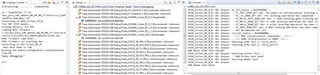
Thank you so much for your support and guidance :-)
--
Thanks & Regards,
Divyesh Patel
Hi James,
In schematic only, that coupling voltage and clock signal voltage. It was coupled with 3.3V instead of VDDS_DDR(1.2V)
--
Thanks & Regards,
Divyesh Patel


