This thread has been locked.

If you have a related question, please click the "Ask a related question" button in the top right corner. The newly created question will be automatically linked to this question.

EVM430-F6779: GUI output results differ from theoretical values

Genius 5485 points
Part Number: EVM430-F6779

Hi experts,

My customer is performing an evaluation using the EVM430-F6779 (TI EVM) and Energy Measurement Design Center (EMDC).
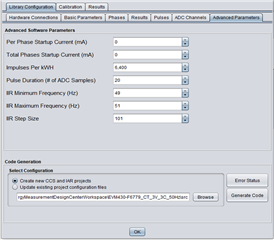
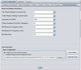
Sample Project:EVM430-F6779_RC_3V_3C_60Hz

As a result of measuring with three types of equipment: a power meter, a watt meter from another manufacturer, and TI EVM, only the TI EVM gave different results.

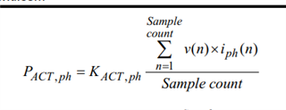
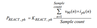
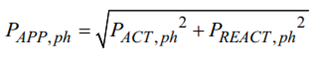
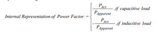
Q1:Are the calculation methods used in the GUI correct? The values of power factor, reactive power, and apparent power seem to be different from the theoretical values.
Q2: Is there a way to correct the calculation method if it is incorrect?
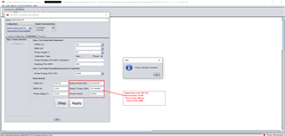
Q3: Is it correct that the GUI results are calculated within the CPU? (The GUI only communicates via UART and displays the results)

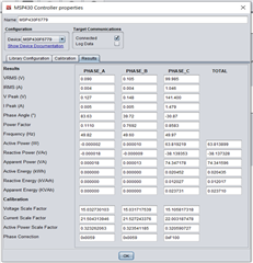
The result is as follows.
Power meters and watt meters from other manufacturers display measured values, while TI EVM displays results on the GUI.

      Digital Power meter   Watt meter from another manufacturer   TI EVM
AC(V) load current(mA)   Voltage(V) Current(A) Power(W) Frequency(Hz) Power Factor(PF) Reactive power(var) Apparent power(VA)   Voltage(V) Current(A) Power(W) Frequency(Hz) Power Factor(PF) Reactive power(var) Apparent power(VA)   Voltage(V) Current(A) Power(W) Frequency(Hz) Power Factor(PF) Reactive power(var) Apparent power(VA)
AC
100
100   100.1 0.081 2.98 50 0.375 7.73 8.33   100.1 0.062 2 50 0.35 6 -   99.9 0.057 2.19 49.97 0.93 0.86 2.37
200   100.1 0.128 5.21 50 0.403 11.9 12.95   100.1 0.108 4 50 0.39 10 -   99.9 0.102 4.3 49.97 0.96 1.24 4.5
300   100.1 0.167 7.3 50 0.434 15 16.82   100.1 0.149 6 50 0.42 14 -   99.9 0.142 6.36 49.97 0.97 1.728 6.61
400   100.1 0.203 9.33 50 0.459 18.1 20.4   100.1 0.187 8 50 0.45 17 -   99.9 0.18 8.4 49.97 0.96 2.3 8.73
500   100.1 0.238 11.43 50 0.478 21.03 23.96   100.1 0.224 11 50 0.47 20 -   99.9 0.216 10.5 49.97 0.96 2.99 10.93
600   100.1 0.272 13..5 50 0.494 23.76 27.39   100.1 0.259 13 50 0.48 23 -   99.8 0.251 12.58 49.97 0.96 3.74 13.13
700   100.1 0.304 15.5 50 0.508 26.38 30.65   100 0.292 15 50 0.5 25 -   99.8 0.284 14.61 49.97 0.95 4.54 15.29
800   100.1 0.337 17.6 50 0.52 28.95 33.94   100 0.326 17 50 0.51 28 -   99.8 0.317 16.67 49.97 0.95 5.4 17.54
900   100.1 0.369 19.7 50 0.53 31.45 37.17   100 0.358 19 50 0.52 31 -   99.8 0.35 18.75 49.97 0.94 6.4 19.82
1000   100.1 0.401 21.8 50 0.541 33.9 40.4   100 0.391 21 50 0.53 33 -   99.8 0.382 20.86 49.97 0.94 7.42 22.13
1250   100.1 0.481 27.1 50 0.561 39.98 48.3   100 0.471 26 50 0.55 39 -   99.8 0.462 26.15 49.97 0.93 10.2 28
1500   100.1 0.558 32.3 50 0.577 45.7 56.1   100 0.549 31 50 0.57 45 -   99.8 0.539 31.28 49.97 0.92 13.3 34
1750   100.1 0.636 37.6 50 0.59 51.5 63.8   99.9 0.627 37 50 0.58 51 -   99.7 0.617 36.61 49.97 0.91 16.85 40.3
2000   100.1 0.714 42.9 50 0.6 57.3 71.6   99.9 0.705 42 50 0.59 57 -   99.7 0.694 41.87 49.97 0.89 20.7 46.7
2250   100.1 0.794 48.3 50 0.606 63.1 79.5   99.9 0.785 47 50 0.6 63 -   99.6 0.774 47.23 49.97 0.88 24.95 53.4
2500   100.1 0.874 53.6 50 0.613 69.2 87.6   99.9 0.865 53 50 0.61 68 -   99.6 0.854 52.59 49.97 0.87 29.5 60.3
2750   100 0.957 59.2 50 0.617 75.4 95.9   99.9 0.948 58 50 0.61 75 -   99.6 0.937 58.07 49.97 0.86 34.62 67.6
3000   100 1.043 64.8 50 0.621 81.9 104.5   99.9 1.034 64 50 0.62 81 -   99.6 1.022 63.65 49.97 0.84 40.18 75.2

Best regards,
O.H

  • Hi O.H,

    1. The calculations should be correct and have been used in many designs and validated previously. My main thought would be on calibration of the device, here's a thread that may assist you. How are calibration values calculated
    2. You would need to adjust the code/calculations if you feel the need to, I do recommend checking the calibration first.
    3. The GUI is only used to display results and send manual calibration factors, calculations are done on the MSP side.'

    Regards,

    Luke

  • Hi Luke,

    Thank you for the reply.

    We will confirm the calibration with the customer.
    I think that at least the "apparent power = V*I", so could you please tell me your opinion?

    Best regards,
    O.H

  • Hi O.H,

    The formulas can be found in the Implementation of a Three Phase Electronic Watt-Hour Meter Using MSP430F677x(A) Section 4.2.1.2

    Apparent power is related to the active (true) power and reactive power and is the hypotenuse in the "power triangle"

    Here's an article to help explain the different types of power and their relations.

    https://www.allaboutcircuits.com/textbook/alternating-current/chpt-11/true-reactive-and-apparent-power/

    Regards,

    Luke

  • Hi Luke,

    The customer performed a calibration and then measured again, but there appears to be a problem with the power factor calculation.

    Q4:Could you please tell me how to display the power factor correctly?
    Q5:Please let us know if you have any comments or suggestions regarding the results below.

    The results of comparing the digital power meter's displayed value and theoretical value with the TI EVM GUI's displayed value and theoretical value are listed below.
    Please refer to the Excel file for details of the calculation formula used.

      Digital Power meter (WT110)
      Voltage(V) Current(A) Power(W) Frequency(Hz) Power Factor(PF) Reactive power(var) Apparent power(VA)
    Display value 100 1.043 64.8 50 0.621 81.9 104.5
    Theoretical value(PF base) 100 1.043 64.7703 50 0.620095694 81.75144181 104.434908
      TI-EVM GUI (EVM430-F6779)
      Voltage(V) Current(A) Power(W) Frequency(Hz) Power Factor(PF) Reactive power(var) Apparent power(VA)
    Display value 99.985 1.046 63.81922 50 0.8583 38.139353 74.347178
    Theoretical value(PF base) 99.985 1.046 89.76471 50 0.858394678 53.66725397 74.34718106
    Theoretical value2(Power base) 99.985 1.046 63.81922 50 0.610217937 82.85520391 104.58431

    [About theoretical formulas]

    • Active power = voltage x current x power factor (Cosθ)
    • Reactive power = voltage x current x inefficiency (Sinθ) = voltage x current x (root (1-power factor^2))
    • Apparent power = root((active power^2)+(reactive power^2))

    Best regards,
    O.H

    Comparison of measurement results between EVM430-F6779 and Power meter (WT110).xlsx

  • Hi OH,

    Let me look into this further, I will get back to you tomorrow.

    Regards,

    Luke

  • Hi OH,

    Can you show the IIR minimum and maximum frequency as well as the IIR step size? These are located in the advanced parameters section. The filters are applied to the power calculations but are not applied to the Vrms and Irms values.

    Regards,

    Luke

  • Hi Luke,

    Can you show the IIR minimum and maximum frequency as well as the IIR step size? These are located in the advanced parameters section. The filters are applied to the power calculations but are not applied to the Vrms and Irms values.

    Attached is the content for 50Hz(left) and 60Hz(right).


    [Additional]

    My customer did an additional comparison experiment at 60Hz.
    The comparison results showed that only the EVM showed different values in power factor, reactive power, and apparent power values compared to the results of the digital power meter and watt meter made by other companies.
    Also, we found that the difference in the frequency setting value on the GUI has no effect.
    *We have rewritten the EVM FW, switched the GUI Prpject file to 50Hz and 60Hz, and performed calibration.

    Based on understanding of "4.2.1 Computation Formulas" in the  Implementation of a Three Phase Electronic Watt-Hour Meter Using MSP430F677x(A) , we think that the cause is the method of calculating reactive power.

    • 4.2.1.1 Voltage and Current
      • No problem
    • 4.2.1.2 Power and Energy
      • In the comparison results, the active power values are all the same, but the reactive power values are clearly different.
        It seems that the TI calculation formula does not use power factor or inefficiency. Reactive power is sampled at a point where the voltage is shifted by 90 degrees, and we believe that this may be the cause.
        Since the value of reactive power is different, the apparent power derived from reactive power is also different from the product of voltage and current.
    • 4.2.1.2 Power Factor calculation formula
      • There is no problem with the calculation formula, but the apparent power is different because the reactive power value is different.
        Furthermore, the power factor also differs as a result.

    Best regards,
    O.H

  • Hi OH,

    I'm going to take sometime to investigate this, they are correct in how the calculations are being done with reactive being a function of active power and a 90 degree shift.

    It seems they are testing the effects of a phase change on the actual input vs their calibration. Would they be interested in changing the formula on their end?

    Regards,
    Luke

  • Hi Luke,

    Would they be interested in changing the formula on their end?

    Yes, they are interested in changing the formula.

    Since they originally used "other company's power meter" to promote their business, it is necessary to define the results of "other company's power meter" as correct.

    Best regards,
    O.H

  • Hi O.H.

    I looked through the variables they should have access to, there are 2 functions related to reactive power that they may want to adjust which is the EM_calcReactivePowerMultAcc and the EM_calcReactivePowerDiv.

    The EM_calcReactivePowerDiv will adjust your scaling factor and multiply by the current phase reactive power, this is a foreground process and called from the EM_processForegroundData. If you're adjusting the function the parameters included should be a clue to what information may be required, with the gEmSWResult containing the results of all calculations done and the gEmSWConfig containing the configuration data.

    The EM_calcReactivePowerMultAcc is a background function which is called in the function EM_perSampleProc (EM_userConfig.c). The phase configuration will contain your voltage and current for the most recent sample. If they want to change how the phase is handled and change from our default 90 degree phase shift this is the function that they would adjust. The resultant will be placed in the gEmSWResult.phaseBGResults 

    I hope this helps, if they want to continue moving forward I may need to get into direct contact with them.

    Regards,
    Luke

  • Hi Luke,

    Thank you for your support.

    Could you please let me know if there is any other way to adjust and check reactive power, apparent power, and power factor other than what you provided (modifying the FW)?
    For example, changing settings on the GUI (EnergyMeasurementDesignCenter), etc.

    Best regards,
    O.H

  • Hi O.H.

    I believe the customer is already suspicious of the power factor being the cause but I'll explain further below.

    Looking back at the original post the GUI is reading a phase of -30.87 which would give you the power factor of 0.8583 (which is what the GUI shows). When you apply this power factor the calculations are correct. But looking at the theoretical power factor of 0.61 your phase would be at 50°. Either the calibration was not done or the phase calibration was done to the wrong degree. Looking at their Excel file they seem to also understand this, so this defines the importance of proper calibration if they want correct readings.

    If you calibrate through the GUI you can calibrate at the 50° phase shift, though typically we calibrate at a 60° phase shift. Here's a video on a full development using the EMDC, at the 10 minute mark is where calibration is done.

    related e2e post: Power Factor, Reactive Power and Apparent Power reading incorrectly

    Regards,
    Luke

  • Hi Luke,

    Sorry, for late the reply. We have not been able to resolve our issue based on the information you provided, so we have left the thread in an unresolved state.
    Let me ask you a few additional questions.

    If you calibrate through the GUI you can calibrate at the 50° phase shift, though typically we calibrate at a 60° phase shift. Here's a video on a full development using the EMDC, at the 10 minute mark is where calibration is done.

    Q1:Regarding phase calibration, if I calibrate with a setting other than 60°, will the correct value not be obtained?
    They performed phase calibration(referenced video at 10 minute) with a different value (52° phase value at actual load and single phase) instead of 60°, but the reactive power, apparent power, and power factor were not the same as the measuring Digital Power meter (WT110).
    ※See the diagram below. Please note that the they does not used equipment used by certification bodies for phase calibration.

    Q2:It have a similar problem in the thread above, but do you know the result? Was it resolved by calibration?

    Q3:Could you please tell me the measurement environment (measuring instrument name, etc.) that TI has confirmed?

    Q4:Is it correct to understand that the active power calculation results are not affected by the reactive power, apparent power, and power factor calculations in question?
    We can confirm that the EVM application note and other calculations are performed separately on the internal calculation block.
    But it would be helpful if you could provide proof that it does not affect the calculation of active power.

    I looked through the variables they should have access to, there are 2 functions related to reactive power that they may want to adjust which is the EM_calcReactivePowerMultAcc and the EM_calcReactivePowerDiv.
    I hope this helps, if they want to continue moving forward I may need to get into direct contact with them.

    Please note that it is difficult for them to the software modifications. We apologize, this has been put on hold for now.

    Best regards,
    O.H

  • Hi OH,

    I will have to get back to answer the last question.

    1. You can calibrate at other degrees, we typically do 60 degrees though.
    2. I can only assume that the original post was solved with the calibration as they did not comeback with further questions.
    3. We use an MTE machine for 3-phase that has a 0.05 class accuracy

    Regards,
    Luke

  • Hi Luke,

    Sorry for the late reply, thank you for the reply.

    And sorry for rush you, is there any update about Q4?
    It would be helpful if you could just tell me the situation.

    Best regards,
    O.H

  • Hi O.H.

    For the active power calculation it takes the instantaneous voltage and current multiplied then summed and divided by the sample count then multiplied by the scaling factor. 

    Reactive power will take a similar formula, but phase shift the voltage by 90 degrees, so it is correlated to active power by the current and voltage.

    Apparent power is directly related to active and apparent power and is root sum of squares between active and reactive power.

    The power factor is the ratio between the active and apparent power.

    Though not calculated like this in the library, the power factor should also be equal to the cosine of the phase angle. (Looking at your GUI the power factor is correct for the shown phase angle so the relation between apparent power and active power is correct. I would think that their phase angle is erroneous). Active power is not directly effected by the Reactive Power, Apparent Power, or Power factor. But will be impacted by the phase angle, voltage, current, and scaling factor.

    Regards,
    Luke

  • Hi Luke,

    Thank you for the reply. Sorry for the additional question.

    Though not calculated like this in the library, the power factor should also be equal to the cosine of the phase angle.

    Q1:What exactly is a library? (Energy Measurement Software Library, ADC Hardware Abstraction Layer)
    By the way, the link to APIGuide at the URL below is broken.
    :https://software-dl.ti.com/msp430/msp430_public_sw/mcu/msp430/EnergyMeasurementDesignCenter/1_40_00_03/release/EnergyMeasurementDesignCenter_1_40_00_03/docs/users_guide/html/Energy_Measurement_Technology_Guide_html/markdown/ch_intro.html#software-api

    (Looking at your GUI the power factor is correct for the shown phase angle so the relation between apparent power and active power is correct. I would think that their phase angle is erroneous).

    Q2:So, could you please tell me what kind of calculation result I would get if I did it at, for example, 52° or -52° instead of 60°?

    Q3:My customer is trying to calibrate at 52° on the GUI, but it doesn't seem to give accurate results.
    Are there any limits to calibration on the phase angle GUI?
    Does it require additional correction in the software?

    Best regards,
    O.H

  • Hi O.H.

    The Library would be in reference to the Energy Metrology Library, a library here is a code base that has functions to fit a specific application and in general are hardware independent. A HAL (Hardware Abstraction Layer) is a file(s) that connects the hardware to the library by abstracting the hardware specific configurations, commands, or peripherals to a general format so the Library can communicate with the hardware.

    Thanks for point me to the broken link, I'll work on getting it fixed. In the .h files all the functions should be defined and have comments that help detail what the function does and requirements on parameters.

    There shouldn't be any issues when using a different angle. What the calibration is doing is calculating the ideal values based on the provided data then getting the actual values from the device. From there the error is calculated as the (Real/Ideal - 1) *100.

    In short,  the error is calculated based on the User Inputs on the calibration GUI and the Ideal vs Real comparison provides a scaling factor or a phase correction based on the provided data. So the angle should not matter as long as the signal input phase angle is the same as your input to the GUI.

    Regards,
    Luke

**Attention** This is a public forum