MSP430FG6626: MSP430FG6626 ADC

Part Number: MSP430FG6626
Other Parts Discussed in Thread: MSP-FET

Tool/software:

Results_06_06.docx

I am using the following eval board MSP-TS430PZ100AUSB along with the microcontoller MSP430FG6626.

I am also suing the program from your website msp430fg662x_cst16_03.c

I managed to get relatively stable results but I still notice fluctuations in the readings like in the document attached. I put the values in question in a red box.

How can I get rid of these fluctuations and increase the accuracy?

Program: msp430fg662x_cst16_03.c

# data points collected = 20

Voltage applied at pins 1 and 2 = 0.2VDC

Thanks,

Yaser

  • Not sure if the noise come from the signal you can short the input pins directly to see the fluctuations. By the way, different gain value of the PGA  also effect it, you can try PGA amplify with 1. 

  • I shorted the differential inputs of CH0 and these are the results I got:

    6540
    6545
    6546
    6548
    6547
    6548
    6548
    6548
    6483
    6549

    There is still some fluctuations. I checked the gain and it is set to 0x000 which corresponds to 1 as per the datasheet.

    I have also tried to measure a sin wave +/- 0.2V I only collected 1000 samples shown in file "AC Results_01.xlsx" attached

    . I have the following questions:

    1- Using the CTSD16, what is the sampling rate? I tried to check the CTSD16 registers and couldn't find a sampling rate defined setting. From the chart measuring 60HZ sine waves, it seems the sampling rate is 4200 per second. How could I increase that.

    2- Why is the signal clipped at the top? How can I get rid of the clipping?AC Results_01.xlsx

    3- I am Running the msp430fg662x_cst16_03.c program from the Resource Explorer, I am no longer able to execute to breakpoints. The run commands totally ignores my breakpoints. I used to be able to stop at breakpoints but for some reason, I am not able to now.

    4- I have been trying to open and write into a file using fopen/frpintf/fclose commands, I could compile fine, but the file I create is always empty.

    Thanks,

    Yaser

  • For your questions:

    1. The sampling rate is depends on when you trigger the ADC to start conversion not configured in register.

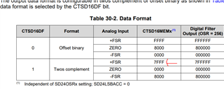
    2. It may be you use the data mode of twos complement that the max value is 32767. 

    By the way please make sure your input voltage are in the valid range below

    3. Dose the break point work at other place? You can also try to close the optimization 

    4. recommend to convert the file into .h or .c file that can be call by the C code directly 

  • 1- What do you mean the sampling rate depends on when we trigger? In case of continuous sampling how is that calculated? 

    2- Even with 7FFF, why do I have 7FFFs when I am measuring a +/-0.2V Sine wave? where is the '0' reference? how is negative values represented if all the data collected as per the file I sent you are less than 7FFF?

    3- if that was the case, why do I get FFFFs when I connect the CH0+ to CH0-, why is zero gives the value close to FFFF (65536)?

    4- The breakpoint doesn't work anywhere else as well.

    5- So, the C program doesn't read or write to a *.dat file?

  • In case of continuous sampling how is that calculated?

    If you are using the continuous sampling mode, the ADC results update frequency is about 34k due the modulator max frequency is about 1.1MHz and it min OSR is 32.

    why do I have 7FFFs when I am measuring a +/-0.2V Sine wave

    What's the data format do you use? What's the CTSD16GAINx value do you set here?

    where is the '0' reference?

    For twos complement,  '0' reference is 0.

    how is negative values represented if all the data collected as per the file I sent you are less than 7FFF?

    Negative values will be 0~0x8000, the highest bit stand set to 0 means negative.

    if that was the case, why do I get FFFFs when I connect the CH0+ to CH0-, why is zero gives the value close to FFFF (65536)?

    You are using the same test code that msp430fg662x_cst16_03.c?

    The breakpoint doesn't work anywhere else as well.

    What's the IDE do you use? And what's the version it is? 

    So, the C program doesn't read or write to a *.dat file?

    I have not try that before, it will more related with what compiler do you use.

  • - In reply to " Whats the data format you use? whats the CTSD16GAINx value you set here?

    I am using the same data format in the example you used in msp430fg662x_ctsd16_03.c

    - If in 2's complement format, '0' reference is '0', then in the excel sheet I shared with you, I am measuring a sine wave of +/-0.2V, why the values are the way they are? In one run, they were all less than 7FFF, and in other runs, they were fluctuating between 0 to FFFF without making any changes in the code.

    - I am using the same code example, the only difference is that I increased the sample size from 8 to 100 and 1000. I increased the array size correctly.

    - I am using Code Composer Studio ver 12.7.0.00007, and the programmer is MSP-FET.4265.AC Results_01.xlsx

  • Hi Yaser,

    I have apply few samples of msp430fg6626 today and will need few days to get it, I also ask our colleague in Dallas to see if any samples there to help do your test. 

    By the way, you can also try to do the test in free run mode and print the ADC results by UART to see if any different there.

  • As per the feedback from yesterday 6/19, I changed the data type of the results[] array from unsigned int to signed int. The results is as shown below. Still only fraction of the signal is recorded.

    I am using internal ref voltage. If it is clipping because of internal voltage, why lots of zero values when it is clearly below ref. voltage?

    I am getting similar results when connecting to ‘0’ as your engineer in Texas.

    Still the sine wave is very distorted, and it is not because of the ref voltage for the following reasons:

    1. I am using the internal voltage ref.
    2. The values that are replaced by zeros are clearly below ref. voltage
    3. I tried to lower the amplitude of the input sine wave to 0.05V but I get the same shape of results.
    4. What are the settings in terms of gain, that you used to get a clean sine wave? (I am using internal ref. voltage and a gain of 1 as per the code msp430fg662x_ctsd16_03.c

    I think the sine wave distortion still needs to be addressed and explained.

  • As we discussed off line it is not shared GND with the signal source.

  • Thank you.. this indeed gave me a sinusoidal wave data collection however it was only the positive half. I needed to offset my signal with enough DC bias to see the full signal. How could I get the ADC for the negative part of the sine wave without  applying a DC offset?

  • You can't, the pin is clamped at about -0.3 V with an ESD diode. If you want a signal that goes below ground, you will need to use something else. In the telemetry system I am familiar with, they used an instrumentation amp with an +/- supply and an offset voltage to move it above ground for the ADC.

  • Yes, in the datasheet we have absolute input range as below that should not lower than AVSS

    For the Keith mentioned is the maximum value 

**Attention** This is a public forum