This thread has been locked.

If you have a related question, please click the "Ask a related question" button in the top right corner. The newly created question will be automatically linked to this question.

TPS65910: TPS65910A3A1 Output will not turn on

Part Number: TPS65910
Other Parts Discussed in Thread: AM3517, AM3505, OMAP-L137,

Hello,

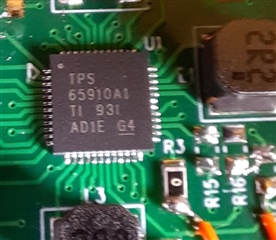
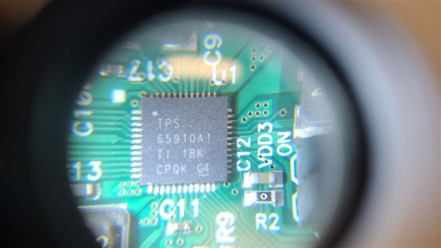
I am working with a TPS65910A3A1, struggling to enable output. When power is applied I get a 1.8V on VRTC but the rest of the output rails will not turn on. I believe it is configured to start when power is applied which is how I intend it to work.

It is configured as follows:
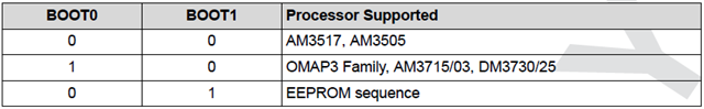
BOOT0 = GND

BOOT1 = VRTC

PWRHOLD = Pull up to VRTC through 10K resistor.  (Tried pulling LOW and leaving floating)

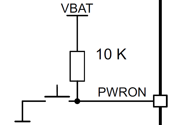
PWRON = Pull up to VRTC through 10K resistor. (Tried pulling LOW and leaving floating)

SLEEP =  GND

BACKUP = +5V Input Voltage (Tried floating)


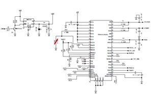
Schematic is attached.

Please note:

  • the 3.3V input source on VDDIO (pin12) is enabled by VAUX33 (pin4) output.
  • R16 is not populated
  • TP1-TP11 are not connected ( floating)
  • I tried grounding pin 31, SW3 per schematic checklist since VDD3 is not used.
  • There are 2.2uF capacitors on VDIG1, VDIG2, VAUX, VAUX33, VDAC18, VRTC (not shown)
  • I am testing without load.

Thank you. 

  • Hello,

      Please set SLEEP = high; the device default setting SLEEPSIG_POL=0 which means SLEEP signal active low.

    Thanks!

    Phil

  • Hi Phil, 

    Thank you for the response. I connected SLEEP to VRTC but got the same results, no power up. I tested with PWRON floating but I can see that it is pulled high internally. I tried PWRHLD in two states, pulled to VRTC and then to ground. 

    I appreciate any additional suggestions you may have. 

  • Hi Bradley
       Please refer to the document "TPS65910Ax User's Guide for AM335x Processors" for more details.

       It looks like PWRON pin needs a falling and rising edge to power on the device. 

    Thanks!

    Phil

  • Hi Phil,

    Thanks for the suggestion. It didn’t resolve the issue.

    My design is based on the TPS65910 Eval board which I was able to get working for my application.

    On the Eval board, the output turns on when power is applied.

    The PWRON signal is floating (internally pulled high).

    The state of the SLEEP signal doesn’t seem to matter.

    The PWRHLD signal enables and disables the output.


    The device I’m using has a different P/N than the device on the Eval board. TPS65910RSL on the Eval board  vs TPS65910A1A3.

    I made the assumption that the two devices were the same except for the voltage levels and start up sequence when set to EEPROM boot mode [1:0].

    It appears there are other differences but I cannot find where they are documented. Can you please let me know where I can find this information?

    I don't see it listed in the  TPS65910x Power Sequencing Configurations document.

    Thank you, 

    Brad

  • Hi Brad,

      Beside of the differences you listed; these devices also have power on/off control difference; like some of them controlled by the PWRHLD signal level to enable and disable the output. I remember the TPS65910A1A3 has been programmed to power on the device by the PWRON pin falling and rising edge. 

      How many boards do you have with the issue? Is it possible the device was damaged? 

    Thanks!

    Phil

  • Hi Phil,

    I made some progress with this issue.

    I found this forum post which indicates that the TPS65910A3A1RSL starts with VRTC in low power mode so any current draw over 0.1mA keeps the device in no supply mode.

    https://e2e.ti.com/support/power-management-group/power-management/f/power-management-forum/874623/tps65910-tps65910a3a1rsl-pmic-is-not-working-vref-0v

    I removed all pull up resistors from the VRTC rail and pulled PWRHLD high to the input voltage. I was able to get the device to turn on and saw good output voltages. I also had to add input capacitance to get it to stay on.

    The current set up is:

    BOOT0 = L

    BOOT1 = L

    PWRON = FLOAT

    SLEEP = FLOAT

    PWRHLD = H (VCC)


    The problem now is that it is in [0:0] boot mode. I need it to be in [1:0] (EEPROM) mode. When I pull BOOT1 high to VRTC or to an external supply(3.3V), it fails to start. I am using a 100K resistor which should be below the 0.1mA threshold. I also tried a 1M resistor but it stayed in [0:0] mode. 

    I tried pulsing PWRHLD and PWRON low but no luck. 

    I don't believe the device is damaged. I see the same results on 5 different boards. 

    Thank you 

    Brad

  • Hi Brad,

      Thanks a lot for telling me the method for the progress! Now, my question is: where did you get these units? I'm wondering if they are programmed properly, since their EEPROM needs to be programmed properly to boot up successfully.   

    Thanks!

    Phil

  • Hi Phil, 

    These were purchased from Mouser in January.  The date code is 931 AD1E. Is there a way to verify the EEPROM program? 

    Thank you, 

    Brad

  • Hi Brad,

      I'll check with our production line and let you know as soon as I get answers. 

    Thanks!

    Phil

  • Hi Brad,

      Can you try this boot mode: BOOT1 = 0, BOOT0 = 1 and check against its "Table 8-3. Fixed Boot Mode: 01". If both 00 and 01 modes working well, then EEPROM programming issue will be investigated ASAP. 

    Thanks!

    Phil

  • Hi Phil,

    I tried the boot mode you suggested: BOOT0 = H, BOOT1 = L and got the same results, no output. VRTC = 1.8V, all other rails off including VREF.

    I used a new board that had never been powered on before to eliminate the chance of a damaged device.

    I confirmed that it would power on in BOOT[0:0] mode, then installed a pullup resistor (10K) from BOOT0 to VRTC.

    I also tried:

    • Transitioning PWRHLD from low to high (VCC) after power applied.
    • Pulling PWRON momentarily low after power applied.
    • SLEEP pin disconnected (internal PD)
    • SLEEP pin pulled high to VRTC with 10K resistor.


    Thanks for your help.

    Brad

  • Hi Brad,

      I got answer now. The devices with PN "TPS65910A3A1" have been programmed for TI AM3517 and AM3505 processors only; they're not able to work in other 2 modes.

    Thanks!

    Phil

  • Hi Phil, 

    Thanks for your help with this. Your explanation corresponds with what I am seeing but doesn't help my situation. Can you please point out where this is documented? The table in your message doesn't really show that it only works in [0:0] mode. 

    Thank you, 

    Brad

  • Hi Phil, 

    I am missing something here. The document TPS65910Ax User's Guide for AM335x Processors makes several references to using the TPS65910A3A1 in EEPROM mode with an AM335x processor. Can you please provide an explanation? 

    Thank you, 

    Brad

  • Hi Brad,

      My bad! I was assigned to this device a few months ago; the case you're dealing with is the first one. I'll work onsite tomorrow; will try to find an EVM to do some test and then update you if I find out a cause. 

    Thanks!

    Phil 

  • Thank you Phil.

  • Hi Brad,

      PFA; they're EVM schematics, user guide and pictures from the EVM I found and used for the following tests:

    1. The EVM has its DUT PN TPS65910A1RSL which is the same PN on your board.
    2. VIN working range is from 3V to 5V. 
    3. The EVM can boot up properly in 3 modes: Boot1:0=00; Boot1:0=01 and Boot1:0=10; no output in Boot1:0=11.
    4. Only PWRHOLD=1 is necessary; all others inputs: PWRON; SLEEP; EN1 and EN2 don't matter.

      Would you please check followings:

    1. All other settings with your board against the EVM schematics settings.
    2. FYI; TPS65910A1RSL is not same as the device you're working with ( TPS65910A3A1). TPS65910A1RSL is compatible with OMAP-L137/138 and TMS320C674x Family processors, using EEPROM config boot1boot0=10 (User guide for OMAPL-137/138 and TMS320C674x family processor: SWCU071A is attached).

      Please let me know if you have further questions. 

    TPS65910 User Guide for OMAPL137, OMAPL138 and C674x_swcu071a.pdfTPS65910 EVM User's Guide (Rev. F)_swcu065f.pdf

    Thanks!

    Phil

  • Hi Phil,

    I was able to get the device to turn on in EEPROM mode. It ended up being the lack of an external crystal in my design. I had intended to use the internal RC oscillator since I am not concerned with the RTC feature of the device.

    I noticed that the data sheet indicates boot mode BOOT[1:0] =0,1 sets the DEVCTRL_REG register to external clock source. I installed a crystal and was able to use BOOT[1:0] =0,1 mode. I then tried BOOT[1:0] =1,0 (EEPROM mode) and found that it turned on.

    There is a bit of a documentation issue here. In theTPS65910Ax User's Guide for AM335x Processors document, the EEPROM setting for the TPS65910A3A1 device doesn’t match what is indicated in Table 2: EEPROM Configuration for TPS65910Ax, even though the TPS65910A3A1 device is listed. Several of the voltage rails such as VDD1, VDD2,and VIO do not match the voltage value documented. The DEVCTRL_REG register is set to external clock source rather than RC which is noted in this table. This table matches what I observed with the eval board which is why I didn’t populate the external crystal, but it doesn’t match the TPS65910A3A1 device. I haven’t checked to see if the sequencing matches yet.

    I think this resolves my issue. I appreciate your help with this. 

    Thanks,  

    Brad

  • Hi Brad,

      Thanks a lot for making the issue resolved and greatly appreciated for pointing out the documentation issue here.

      Would you please list those mismatches you've found and sequencing mismatches well if you find any; so, I'll verify those mismatch later and make connections with the document. 

    Thanks a lot!

    Phil

  • Hi Phil,

    Sorry for the delay in getting back to you on this.

    Originally,  I thought I was using TPS65910A3A1. I double checked this and found that I actually have TPS65910A1RSL. This corresponds with the markings on my device and the EVM board you tested.

    I observed that the power on sequence is:

    SLOT 1: VDIG1 @ 1.8V

    SLOT 2: VDD1 @ 1.2V

    SLOT 3: VDD2 @ 1.2V

    SLOT 4: VDIG2 @ 1.2V ; VIO @ 1.8V

    SLOT 5: VAUX33 @ 3.3V ; VPLL @ 3.3V ; VMMC @ 3.3V

    SLOT 6: VAUX2 @ 3.3V ; VAUX1 @ 1.8V

    SLOT 7: VDAC @ 1.8V


    Most of these voltages correspond with the “TPS65910 User Guide For OMAP3 Family of Processor” document you provided but there are discrepancies especially with the timing. However, nowhere in this document is the TPS65910A1 device specifically referenced. I would think that this document is referring to the TPS65910 device rather than the TPS65910A1.

    My interpretation was that when documents reference TPS65910Ax,  TPS65910A1 is included, specifically the TPS65910Ax User's Guide for AM335x Processors (Rev. F) document.  This is what my design is based on. 

    I’d like to know where I can find accurate documentation about the TPS65910A1 device.

    Thanks, 

    Brad

  • Hi Brad,

      Thanks a lot for the information! You're right! We need an accurate documentation about the TPS65910A1 device. 

      I think this User Guide should be the closest one according to the table (screenshot below) from generic TPS65910 datasheet; although some mismatches still be seen. 


    Please keep us updated for what you find so we can have the document revised later for other users. 


    Thanks a lot!

    Phil