This thread has been locked.

If you have a related question, please click the "Ask a related question" button in the top right corner. The newly created question will be automatically linked to this question.

AM4378: Linux randomly hanging at start-up and DDR fails memorytester

Part Number: AM4378
Other Parts Discussed in Thread: AM3358, , TPS65218D0, TPS65218

Hi, 

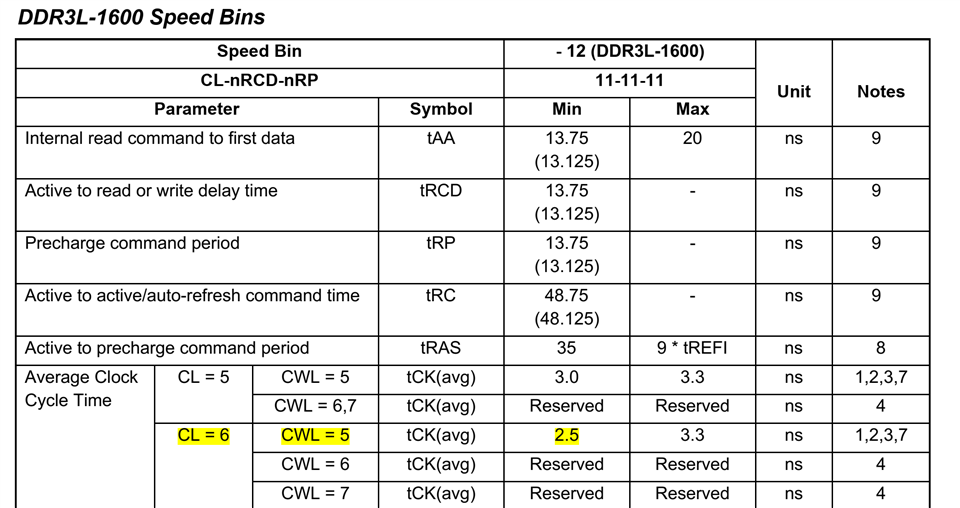
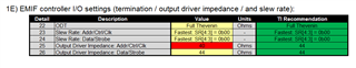
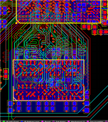
We have a custom board with AM4378 processor and a single AS4C256M16D3LB-12BIN as our DDR. We use single DDR without VTT termination. We have made all the EMIF configurations using EMIF tool. We are running our own Linux image on the board which have been tested in some other design using TI's AM3358. We modified the device tree and kernel settings for the new board and used AM4378EVM as reference too. Attached you can find our DDR schematics and EMIF settings. 

The problem we are seeing is that Linux kernel is starting but hangs randomly or stops due to kernel panic during startup at different places but mostly when trying to copy from rootfs. It sometimes goes through and reaches the command line. However 50% of the time it hangs or stops with kernel panic. 

We have done memtest at u-boot and did not find any issues however, at times when we can reach command line, we run memorytester and it gives Stuck Address error; FAILURE: possible bad address line at offset XXXXX. (The XXX address changes each time). All other tests of memorytester is OK...When we run the memorytester in a small section (like 256K or 512K) we usually do not see any error but when we do at more than 1MB, we always have the stuck address error.

We need your expertise in this problem. Do you think that this is a memory hardware problem, (ie memory is gone bad) or does it have anything to do with our EMIF or kernel settings?

What do you suggest that we do, to find where the problem is? 

Also, please note that in the EMIF tool, we have entered Byte 2 and Byte 3 trace lengths as zero because we are using a single DDR. Can you please confirm this and rest of the EMIF settings please for our setup? 

Time is of the essence in this project so you prompt response would be very much appreciated. Thank you!

 1108.DDR_Schematic.pdf 8171.SPRAC70A_AM437x_EMIF_Configuration_Tool_V21.xlsx

  • Hi Berkay, 

    -i checked your config and the one thing that doesn't look right is your setting for CAS Latency, which should be 6 based on below.  Can you try with that setting

    If you still see an issue, can you answer the following:

    -do you see a similar issues across multiple boards?  

    -does the issue occur at lower frequency (eg, 303MHz)

    -can you dump the EMIF registers to ensure the values from the spreadsheet match what is written to the registers

    Regards,

    James

  • Hi James, 

    Thanks for your response. We only had a handful of these prototypes made but we see it in all of them. However, we also had some PMIC voltage issues in the beginning, (asked about it too here:https://e2e.ti.com/support/processors-group/processors/f/processors-forum/1134646/am4378-vdd_mpu_mon-not-working-as-pmic-feedback) Even though the DDR voltage was never wrong, we still have the suspicion if these voltage issues in the beginning caused any damage to hardware. 

    We have changed the CAS latency to 6 per your recommendation and also tried it with 303mhz. The results are the same, kernel panic occurs most of the time during start-up at different times. We get "Unable to handle kernel NULL pointer dereference at virtual address........." error. 

    We have checked EMIF registers and they seem correct. I have copied them below. The only thing we noticed was that the value for EMIF4D_EXT_PHY_CTRL_36 and SHADOW at 0x4C000318 & 0x4C00031C is read as 00000177 instead of 00000077 but this could be a status assignment, still wanted to point it out to you. 

    => md 0x4c000000 c8
    4c000000: 50440500 40000004 61a05332 00000000 ..DP...@2S.a....
    4c000010: 00000c30 00000c30 eaaad4db eaaad4db 0...0...........
    4c000020: 266b7fda 266b7fda 5f7f867f 5f7f867f ..k&..k&......
    4c000030: 00000000 00000000 000000a0 000000a0 ................
    4c000040: 00000000 00000000 00000000 00000000 ................
    4c000050: 00000000 07770000 9000190a 00042727 ......w.....''..
    4c000060: 00002011 00000000 00000000 00000000 . ..............
    4c000070: 00000000 00000000 00000000 00000000 ................
    4c000080: 004186ff 000307dd 00010000 00000000 ..A.............
    4c000090: 00c7576e 00000000 00090000 00090000 nW..............
    4c0000a0: 00000000 00000000 00000000 00000000 ................
    4c0000b0: 00000000 00000000 00000000 00000000 ................
    4c0000c0: 00000000 00000000 50074894 00000000 .........H.P....
    4c0000d0: 00000000 00000000 80000000 00000000 ................
    4c0000e0: 00000000 00048009 00048009 00000000 ................
    4c0000f0: 00000000 00000000 00000000 00000000 ................
    4c000100: 80000001 80000094 00000000 00000000 ................
    4c000110: 00000000 00000000 00000000 00000000 ................
    4c000120: 80000405 000fffff 00000000 00000000 ................
    4c000130: 00000000 00000000 00000000 00000000 ................
    4c000140: 00000000 000931f3 00012a93 00000000 .....1...*......
    4c000150: 00020000 00000099 00000924 00000042 ........$...B...
    4c000160: 00000044 00000000 00000000 00000000 D...............
    4c000170: 070000a0 0700009f 07000700 07000700 ................
    4c000180: 00000000 007c00c4 00b800c7 02df030f ......|.........
    4c000190: 03e1030f 00000000 003c0084 00780087 ..........<...x.
    4c0001a0: 02df030f 03e1030f 00000000 10300021 ............!.0.
    4c0001b0: 00000000 00000000 00000000 00000000 ................
    4c0001c0: 00000000 00000000 00000000 00000000 ................
    4c0001d0: 00000000 00000000 00000000 00000000 ................
    4c0001e0: 00000000 00000000 00000000 00000000 ................
    4c0001f0: 00000000 00000000 00000000 00000000 ................
    4c000200: 00040100 00040100 00000000 00000000 ................
    4c000210: 00000000 00000000 00000000 00000000 ................
    4c000220: 00000000 00000000 00000000 00000000 ................
    4c000230: 00400040 00400040 00400040 00400040 @.@.@.@.@.@.@.@.
    4c000240: 00400040 00400040 00400040 00400040 @.@.@.@.@.@.@.@.
    4c000250: 00400040 00400040 00400040 00400040 @.@.@.@.@.@.@.@.
    4c000260: 00400040 00400040 00400040 00400040 @.@.@.@.@.@.@.@.
    4c000270: 00400040 00400040 00400040 00400040 @.@.@.@.@.@.@.@.
    4c000280: 00000000 00000000 00000000 00000000 ................
    4c000290: 00000000 00000000 00000000 00000000 ................
    4c0002a0: 00000000 00000000 00000000 00000000 ................
    4c0002b0: 00600020 00600020 40010080 40010080 .`. .`....@...@
    4c0002c0: 08102040 08102040 00200020 00200020 @ ..@ .. . . . .
    4c0002d0: 00200020 00200020 00200020 00200020 . . . . . . . .
    4c0002e0: 00200020 00200020 00200020 00200020 . . . . . . . .
    4c0002f0: 00000000 00000000 00000000 00000000 ................
    4c000300: 00000000 00000000 00000000 00000000 ................
    4c000310: 00000000 00000000 00000177 00000177 ........w...w...

  • Ok, your configuration looks good.

    Can you monitor VDDS_DDR and VDD_CORE, especially during times of high activity (eg, during rootfs copy)?  Looking for droops or other noise on these supplies

    How did you arrive at the IO settings on the first page of the spreadsheet?  Did you perform signal integrity sims on the board, or did you just go with the default?  Can you try decreasing Output driver impedance of Addr/Ctrl/Clk?

    Does memtest in u-boot always pass, even if you test over a large memory region (like you do in the kernel when it fails)

    Do you have JTAG access to your board?

    Were all of the DDR layout guidelines in the datasheet followed?  Especially trace length and skew matching for addr/ctrl signals.

    It is tough to say if the issue stems from your earlier power issues.  I'd say if you are seeing the same behavior on all of your boards, then probably not.  

    Regards,

    James

  • Hi James, 

    Can you monitor VDDS_DDR and VDD_CORE, especially during times of high activity (eg, during rootfs copy)?  Looking for droops or other noise on these supplies

    We will look into this. 

    How did you arrive at the IO settings on the first page of the spreadsheet?  Did you perform signal integrity sims on the board, or did you just go with the default?  

    We went with the default values and did not perform any signal integrity sims. 

    Can you try decreasing Output driver impedance of Addr/Ctrl/Clk?

    Do you mean adjusting the values of line 1E-25) on the EMIF tool? If, so should we try with 33, 36 and 40 ohms? (Anything we choose out of the recommended values turns red.) 

    Does memtest in u-boot always pass, even if you test over a large memory region (like you do in the kernel when it fails)

    Yes. Our ram is 512M and we can test between 0-480M (0x80000000 - 0x9d000000). After that memtest cannot continue, probably due to uboot itself being in that area. 

    Do you have JTAG access to your board?

    Yes and we do have a XDS110 probe but we are not experienced in using the JTAG, so we could not really run any scripts there yet.  

    Were all of the DDR layout guidelines in the datasheet followed?  Especially trace length and skew matching for addr/ctrl signals.

    Yes, all the rules of thumbs were applied. This is an 8 layer board. Below picture shows routing layers (GND/PWR layers hidden) 

  • One other thing that I wanted to ask it regarding PLL parameters. For the get_dpll_ddr_params function, we used the gp_evm_dpll_ddr params for our board as below:

    const struct dpll_params dpll_per[NUM_CRYSTAL_FREQ] = {
    {400, 7, 5, -1, -1, -1, -1}, /* 19.2 MHz */
    {400, 9, 5, -1, -1, -1, -1}, /* 24 MHz */
    {384, 9, 5, -1, -1, -1, -1}, /* 25 MHz */
    {480, 12, 5, -1, -1, -1, -1} /* 26 MHz */
    };

    const struct dpll_params epos_evm_dpll_ddr[NUM_CRYSTAL_FREQ] = {
    {665, 47, 1, -1, 4, -1, -1}, /* 19.2*/
    {133, 11, 1, -1, 4, -1, -1}, /* 24 MHz */
    {266, 24, 1, -1, 4, -1, -1}, /* 25 MHz */
    {133, 12, 1, -1, 4, -1, -1} /* 26 MHz */
    };

    const struct dpll_params gp_evm_dpll_ddr = {
    50, 2, 1, -1, 2, -1, -1};

    Based on our setup (24MHz main clock, 400MHz DDR Clock, etc.) are we using the correct parameters? 

    Thanks again for your help. 

  • For the addr driver impedance, yes choose each of those even though the spreadsheet turns red and note any change in behavior

    For the PLL, yes, you should be using dpll_params_gp_evm_dpll_ddr.  This will give you (24MHz * 50)/(2+1) = 400MHz.  You may want to probe the DDR clock to ensure you are outputting 400MHz.  

    When you perform each test, are you doing a full power cycle on the board, or just resetting the processor?  Can you try one or the other and note any change in behavior.

    If you are using a PMIC, do you have the ability to adjust VDD_CORE voltage?

    Regards,

    James

  • Hi James, 

    We are using the TPS65218D0 PMIC but we can only adjust VDD_CORE voltage from I2C. The current core voltage of VDD_CORE and VDD_MPU is at 1.1V as recommended. However, in the beginning due to VDD_MPU_MON not working correctly, we had seen voltage peak to 3V at VDD_MPU momentarily. So we are trying to understand if this might have caused any damage to the MPU but if it had caused damage, would we still be able to boot all the way sometimes? 

    We have done boot test after changing the impedance of Addr/Ctrl/Clk. Attached you can find a table of our boot attempts and resulting errors. We tried to do at least 10 attempts with PMIC reset. We did try full power down of the board, but it takes too long due to our supercap backup setup, so we did not do it for all attempts. The times we did, there was no correlation and PMIC reset also does full power cycle, so it should not matter I think.

    I also attached our PMIC and power schematics for reference. I have previously shared our DDR schematics. 

    Can you please look at the boot results and schematics and let us know what you think? Thank you. 

    AM437x_power_sch.pdf     

     AM437x Linux Bootup Trials.xlsx 

  • Berkay, it's hard to say whether or not the high voltage damaged anything.  i think since you are having some success, it should be fine, but may want to look into getting a fresh device on a board if possible.

    If you can adjust VDD_CORE via i2c, then one experiment would be to adjust VDD_CORE closer to its max voltage (1.1V +5%).  This will help determine if you are getting any voltage droops on that rail or other effects of noise on the power supply.  

    Nothing really jumped out on the results you sent.  Still not sure why you are only seeing this when booting kernel.  What is your boot media?  Is there any verification you are doing to verify the contents of the image in DDR after kernel is copied into DDR?

    You said you weren't experienced with JTAG, but can you connect to the A9 core and view DDR memory in a memory window?

    Regards,

    James  

  • Hi James, 

    We are using SD Card (mmc0) to boot. We have connected the JTAG connector and verified that the uImage is copied correctly. We also have seen that the EMIF registers in the DDR memory window are correct. 

    We were not able to change the VDD_CORE yet. Is there anyway we can do this at boot? By the way we have monitored VDDS_DDR and VDD_CORE during boot but could not notice anything unexpected.

    Question: We have copied AM4378EVM SDK and modified the EMIF settings from the tool. Is this enough to correctly setup our DDR? We are using a single DDR device vs. EVM's dual DDR device, is there anywhere this is defined? 

    With JTAG setup, is there anything we can do to further deep-dive into our memory and find out why we keep getting different memory errors? 

    Thanks. 


  • Hi James, 

    One more thing we did today. We have downloaded the dss files from https://git.ti.com/cgit/sitara-dss-files/am43xx-dss-files/ and ran the am43xx-ddr-analysis.dss with Code Composer Studio. Below you can find the output files.

    Are you able to see anything wrong here?

    am43xx-ddr-analysis_2022-09-20_220128.txt
    CONTROL: device_id = 0x2b98c02f
      * AM43xx family
      * Silicon Revision 1.2
    
    CONTROL: control_status = 0x00400301
      * Bit 26 (SYSBOOT18=0): Do not route EXTCLK to CLKOUT2
      * Bits 23:22 (SYSBOOT15:14=1): 24 MHz
    
    CM_CLKSEL_DPLL_DDR = 0x00003202
      * DPLL_MULT = 50 (x50)
      * DPLL_DIV = 2 (/3)
    
    CM_DIV_M2_DPLL_DDR = 0x00000221
      * CLKST = 1: M2 output clock enabled
      * DIVHS = 1 (/1)
    
    CM_DIV_M4_DPLL_DDR = 0x00000222
      * CLKST = 1: M4 output clock enabled
      * DIVHS = 2 (/2)
    
    DPLL_DDR Summary
     -> F_input = 24 MHz
     -> CLKOUT_M2 = DDR_PLL_CLKOUT = 400 MHz
     -> CLKOUT_M4 = DLL_CLKOUT = 400 MHz
    
    EMIF: SDRAM_CONFIG = 0x61a05332
      * SDRAM_TYPE = DDR3
      * Bits 26:24 (reg_ddr_term) set for RZQ/4 (001b)
      * Bits 19:18 (reg_sdram_drive) set for RZQ/6 (00b)
      * Bits 17:16 (cwl) set for 5 (00b)
      * NARROW_MODE=1 (16-bit wide)
      * Bits 13:10 (CL) set for 6
      * Bits 9:7 (ROWSIZE) set for 15 row bits
      * Bits 6:4 (IBANK) set for 8 banks
      * Bit 3 (EBANK) set for 1 chip select (CS0)
      * Bits 3:0 (PAGESIZE) set for 10 column bits
    
    EMIF: PWR_MGMT_CTRL = 0x000000a0
    
    DDR PHY: DDR_PHY_CTRL_1 = 0x00048009
      * PHY_INVERT_CLKOUT=1.
      * READ_LAT=9, (corresponds correctly with CL and PHY_INVERT_CLKOUT)
    
    DDR PHY: EXT_PHY_CTRL_1 = 0x00040100
    
    DDR PHY: EXT_PHY_CTRL_36 = 0x00000177
      * Configured as recommended.
    
    CTRL_DDR_ADDRCTRL_IOCTRL = 0x00000084
      * Bits 9:5 control ddr_ck and ddr_ckn
        - Slew fastest
        - Drive Strength 9 mA
      * Bits 4:0 control all other address/control pins
        - Slew fastest
        - Drive Strength 9 mA
    
    CTRL_DDR_ADDRCTRL_WD0_IOCTRL = 0x00000000
    CTRL_DDR_ADDRCTRL_WD1_IOCTRL = 0x00000000
      * [ddr_a0    ] Pullup/Pulldown disabled
      * [ddr_a1    ] Pullup/Pulldown disabled
      * [ddr_a2    ] Pullup/Pulldown disabled
      * [ddr_a3    ] Pullup/Pulldown disabled
      * [ddr_a4    ] Pullup/Pulldown disabled
      * [ddr_a5    ] Pullup/Pulldown disabled
      * [ddr_a6    ] Pullup/Pulldown disabled
      * [ddr_a7    ] Pullup/Pulldown disabled
      * [ddr_a8    ] Pullup/Pulldown disabled
      * [ddr_a9    ] Pullup/Pulldown disabled
      * [ddr_a10   ] Pullup/Pulldown disabled
      * [ddr_a11   ] Pullup/Pulldown disabled
      * [ddr_a12   ] Pullup/Pulldown disabled
      * [ddr_a13   ] Pullup/Pulldown disabled
      * [ddr_a14   ] Pullup/Pulldown disabled
      * [ddr_a15   ] Pullup/Pulldown disabled
      * [ddr_ba2   ] Pullup/Pulldown disabled
      * [ddr_ba1   ] Pullup/Pulldown disabled
      * [ddr_ba0   ] Pullup/Pulldown disabled
      * [ddr_wen   ] Pullup/Pulldown disabled
      * [ddr_rasn  ] Pullup/Pulldown disabled
      * [ddr_casn  ] Pullup/Pulldown disabled
      * [ddr_nck   ] Pullup/Pulldown disabled
      * [ddr_ck    ] Pullup/Pulldown disabled
      * [ddr_cke   ] Pullup/Pulldown disabled
      * [ddr_csn1  ] Pullup/Pulldown disabled
      * [ddr_csn0  ] Pullup/Pulldown disabled
      * [ddr_resetn] Pullup/Pulldown disabled
      * [ddr_odt1  ] Pullup/Pulldown disabled
      * [ddr_odt0  ] Pullup/Pulldown disabled
    
    CTRL_DDR_DATA0_IOCTRL = 0x00000084
      * ddr_d0 Pullup/Pulldown disabled
      * ddr_d1 Pullup/Pulldown disabled
      * ddr_d2 Pullup/Pulldown disabled
      * ddr_d3 Pullup/Pulldown disabled
      * ddr_d4 Pullup/Pulldown disabled
      * ddr_d5 Pullup/Pulldown disabled
      * ddr_d6 Pullup/Pulldown disabled
      * ddr_d7 Pullup/Pulldown disabled
      * ddr_dqm0 Pullup/Pulldown disabled
      * ddr_dqs0 and ddr_dqsn0 Pullup/Pulldown disabled
      * Bits 9:5 control ddr_dqs0, ddr_dqsn0
        - Slew fastest
        - Drive Strength 9 mA
      * Bits 4:0 control ddr_d[7:0], dqm0
        - Slew fastest
        - Drive Strength 9 mA
    
    CTRL_DDR_DATA1_IOCTRL = 0x00000084
      * ddr_d8 Pullup/Pulldown disabled
      * ddr_d9 Pullup/Pulldown disabled
      * ddr_d10 Pullup/Pulldown disabled
      * ddr_d11 Pullup/Pulldown disabled
      * ddr_d12 Pullup/Pulldown disabled
      * ddr_d13 Pullup/Pulldown disabled
      * ddr_d14 Pullup/Pulldown disabled
      * ddr_d15 Pullup/Pulldown disabled
      * ddr_dqm1 Pullup/Pulldown disabled
      * ddr_dqs1 and ddr_dqsn1 Pullup/Pulldown disabled
      * Bits 9:5 control ddr_dqs1, ddr_dqsn1
        - Slew fastest
        - Drive Strength 9 mA
      * Bits 4:0 control ddr_d[15:8], ddr_dqm1
        - Slew fastest
        - Drive Strength 9 mA
    
    CTRL_DDR_DATA2_IOCTRL = 0x00000084
      * ddr_d16 Pullup/Pulldown disabled
      * ddr_d17 Pullup/Pulldown disabled
      * ddr_d18 Pullup/Pulldown disabled
      * ddr_d19 Pullup/Pulldown disabled
      * ddr_d20 Pullup/Pulldown disabled
      * ddr_d21 Pullup/Pulldown disabled
      * ddr_d22 Pullup/Pulldown disabled
      * ddr_d23 Pullup/Pulldown disabled
      * ddr_dqm2 Pullup/Pulldown disabled
      * ddr_dqs2 and ddr_dqsn2 Pullup/Pulldown disabled
      * Bits 9:5 control ddr_dqs2, ddr_dqsn2
        - Slew fastest
        - Drive Strength 9 mA
      * Bits 4:0 control ddr_d[23:16], ddr_dqm2
        - Slew fastest
        - Drive Strength 9 mA
    
    CTRL_DDR_DATA3_IOCTRL = 0x00000084
      * ddr_d24 Pullup/Pulldown disabled
      * ddr_d25 Pullup/Pulldown disabled
      * ddr_d26 Pullup/Pulldown disabled
      * ddr_d27 Pullup/Pulldown disabled
      * ddr_d28 Pullup/Pulldown disabled
      * ddr_d29 Pullup/Pulldown disabled
      * ddr_d30 Pullup/Pulldown disabled
      * ddr_d31 Pullup/Pulldown disabled
      * ddr_dqm3 Pullup/Pulldown disabled
      * ddr_dqs3 and ddr_dqsn3 Pullup/Pulldown disabled
      * Bits 9:5 control ddr_dqs3, ddr_dqsn3
        - Slew fastest
        - Drive Strength 9 mA
      * Bits 4:0 control ddr_d[31:24], ddr_dqm3
        - Slew fastest
        - Drive Strength 9 mA
    
    CONTROL: CTRL_DDR_IO = 0x00000000
      * Bit 31: DDR_RESETn controlled by EMIF.
    
    CONTROL: CTRL_VTP = 0x00010167
      * VTP not disabled (expected in normal operation, but not DS0).
    
    CONTROL: CTRL_VREF = 0x00000000
      * VREF supplied externally (typical).
    
    CONTROL: CTRL_DDR_CKE = 0x0000000f
      * CKE0 controlled by EMIF (normal/ungated operation).
      * CKE1 controlled by EMIF (normal/ungated operation).
    
    CONTROL: CTRL_EMIF_SDRAM_CONFIG_EXT = 0x0002c163
      * Bit  17:    NARROW_ONLY = 1
      * Bits 15:14: phy_num_of_samples = 3 -> 128 samples, full leveling
      * Bit  13:    phy_sel_logic = 0 (Recommended)
      * Bit  12:    phy_all_dq_mpr_rd_resp = 0
      * Bits 11:09: phy_output_sts_select = 0
      * Bit   8:    dynamic_pwrdn_en = 1
      * Bits 06:05: phy_rd_local_odt = 3, Half Thevenin load
      * Bit   3:    dfi_clock_phase_ctrl = 0
      * Bit   1:    en_slice_1 = 1 (CMD PHY1)
      * Bit   0:    en_slice_0 = 1 (CMD PHY0)
    

    am43xx-ddr-config_2022-09-20_220128.csv

  • Berkay, you can use I2C commands in uboot to change the VDD_CORE voltage.  Here's an example of changing DCDC3 on the TPS65218

    => i2c dev 0 # Setting bus to 0

    => i2c mw 0x24 0x10 0x65  #set password protection reg with addr XOR 0x7d = 0x65

    => i2c mw 0x24 0x18 0x08  #set DCDC3 to desired voltage (bits [5:0] from the table).  The 0x08 is 1.1V

    => i2c mw 0x24 0x1a 0x46  #set the GO Disable bit (GODSBL)

    You can readback using i2c md 0x24 0x18 to ensure the change sticks

    You would want to bump it up from 1.1V.  I would experiment with trying these commands out by adjusting it down in voltage first, just to make sure you have the right sequence.  

    The 2 devices on the EVM is just allowing the AM43x device to use the full 32-bit data bus.  By choosing x16 in the tool, the controller is setting up for 'narrow' mode (ie, 16-bit data bus).  If this wasn't right, you'd be having more catastrophic problems because you 'd be missing half of the data bus.

    The DSS script dump doesn't show anything unusual.  It appears you configuration is pretty typical.

    What you can do in CCS is connect after a failure (ensure no GEL files are run automatically), open up a memory window in the DDR region (0x80000000 and higher), and see if you can peek/poke values successfully.  You can also put it in continuous refresh mode to check for stability, and there are memory fill functions in the menu you can also try.  All of this is at slow transfer speeds, so if it is just a problem at high bandwidth, you probably won't see a failure.  This is mainly just checking to see if the configuration got corrupted after boot.

    You can also take register dumps of the EMIF after each boot.  I'd be interested in the seeing the comparison between a register dump after a successful boot and a failed boot.  We might be able to detect some differences in the training results, or maybe if the registers are corrupted.

    Is there anything during kernel boot that could be causing a high noise environment?  Something that is enabled in the kernel (and not in uboot)?  Maybe one experiment would be to start stripping out drivers or modules that are initialized during kernel boot.  Try to make the boot a simple as possible, maybe a certain peripheral or other device on the board is causing an issue with the DDR address/data bus.

    Are you using a crystal for your 24MHz input?  Is it possible to temporarily change that to an LVCMOS oscillator?  I've seen several instances over the years of noise coupling into the crystal circuit and causing random issues like you describe.  The external square wave will eliminate the effects of this.

    Regards,

    James