This thread has been locked.

If you have a related question, please click the "Ask a related question" button in the top right corner. The newly created question will be automatically linked to this question.

6416 PCI Issue

Other Parts Discussed in Thread: TMS320C6416T

Hi Champs:

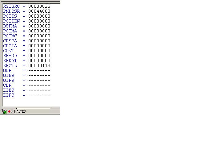
My customer is having an intermittent PCI issue on 6416. Please see the attached doc file for more information on data being captured..  This is an intermittent problem, and out test (software and hardware) seem to work correctly most of the time.

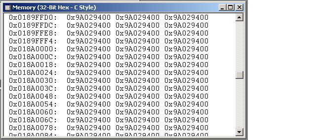
This attached doc  describes a failure condition we see while trying to write to the DSP Internal RAM memory across the PCI bus.  We have only the processor and DSP on the PCI bus.

Thanks for your help.

Pradhyum

FailureDuringRamWriteRead.doc
  • Hi Pradhyum,


    is this 6416 or 6416T? Which silicon revision?

    Have a look at the respective erratas. There are some related to PCI that might fit your case ...

    Kind regards,

    one and zero

  • 6416T, Revision 2.0.

    Don't see anything in the errata that applies to this design.  Problem occurs during all writes, or write/read combinations.

    Any thoughts?

    Thanks,


  • ... here some ideas to check:

    1. What's the power sequencing? IO before core?

    2. The PCI_EN pin must be driven valid at all times and the user must not switch values throughout device operation. Is that fulfilled?

    Kind regards,

    one and zero

  • ... one more thing ...

    Are you able to connect to the DSP via JTAG?

    Can you read out the PCI registers using CCS?

    Did the last write via PCI arrive in the DSPs memory?


    Kind regards,

    one and zero


    • We have modifed the hardware so that the Core comes up before the IO, and still see the issue
    • the PCI_EN pin is pulled high with 1k at all times.  There is nothing else driving this signal.
    • We are able to connect via JTAG and read the PCI registers.
    • The LAST sucessful write DID make it fine, but the current write hanging up did NOT arrive in the DSP memory.  In fact, in cases where the "hang" occurs, there are several writes scattered throughout memory that did not make it either.
    • While connected via JTAG, resetting the DSP (via code composer) will release the DSP from it's hang state, and the PCI bus transactions continue on.

    -Dano

    • We are not able to implement the IO before CORE errata on this design.  The pad is completely burried.
    • We have modified our hardware so that the Core voltage comes up before the IO.  No change.

    -D

    • Here is a dump of the PCI registers from Code Composer via the JTAG while the PCI bus is in "target retry"
    • PCI_EN is not being "driven" but is pulled high with a 1k resistor.

  • On C641x/C671x devices I have traditionally seen 2 main culprits for HPI/PCI lockups:

    1)       Accesses to the 0x40000000 – 0x4FFFFFFF memory range.  READS OR WRITES.  (Look for this using advanced event triggering / Unified Breakpoint Manager.)
    2)       EDMA accesses to a “hung” EMIF (i.e. CE space where it waits forever).  Since PCI also goes through EDMA this would ultimately cause PCI to hang as well.


  • Interesting thoughts.

    The failure occurs well below the 0x40000000 address range.  We are only testing within the 1st 1MEG of space, and the L2CACHE is configured for ALL SRAM.  I have however tried running smaller ranges in the memory test (eliminating the possibilty of misconfiguring the L2CACHE), and we still see the failures.

    We are in host boot mode however, and haven't yet let the processor go.  The DMA controller is disabled for all channels.

    I've also tried performing the test on the SDRAM (EMIFA), and still see the failures.  The issue seems to be PCI related and not memory related.


  • Sorry, I forgot that you have not yet released the DSP from reset.  The cases I mentioned generally occurred after the DSP core had been released from reset.  If for example they derefenced a corrupted pointer or something like that and accessed the 0x40000000 memory range it would cause the PCI/HPI to hang.  Sounds like that's not the situation for you.

    If you have not yet even released the DSP from reset then I would suspect something much more fundamental:

    • What frequency is your input clock to the processor?
    • How are you configuring the PLL pins?
    • Can you setup an oscilloscope in infinite persistence mode and monitor the ripple on your power rails (as close as possible to the DSP)?

    That last bullet is particularly important.  A huge number of these abnormalities result from power supply issues.

    Brad


  • Thanks Brad,

    We have released the DSP from reset, but it is in its "stalled" condition, because we haven't written to the DSPINT bit to initiate the boot process.

    It is while we are in this stalled state, that we are writing the DSP code image to the internal RAM, that we see the problem.

    • Clock frequency is 50MHz
    • PLL is x20 (11)
    • Looking at power supply ripple was the 1st thing we did.  Good thought, as it seems likely given the symptoms.  We have spent lots of time looking at the rails, and they are well regulated and filtered according to your design recommendations.

    Thanks again,

    -D

  • 0243.GppPullsIframeTooSoon.pdf 

    This attachment shows that the slow DSP requires 2 retries, but at some point, the Gpp asserts IFRAME again.  Not sure why the DSP can cause this?  Comments are inline in the file.  Please advise.

    Note:  The memory test is a 2 pass test, writing addr into addr for the 1st pass, then writing the complimented address into address for the 2nd pass.  This explains why there is address data in the latter part of the memory, not yet overwritten by the 2nd pass (complimented data).

    Thank you,

    -D

  • Dano,

    I think you nailed the issue with your final comment in your pdf you attached:

    "Summary: The Gpp is asserting FRAME_N in the middle of the single-beat transaction when it shouldn’t."

    I agree with you and believe the issue is with your GPP.  The PCI spec states:

    "Once FRAME# has been deasserted, it cannot be reasserted during the same transaction."

    The falling edges of DEVSEL# and TRDY# happen to correspond precisely with this second (illegal) assertion of FRAME#. I think you need to figure out why your GPP is asserting FRAME# a second time.

    Brad


  • Thanks Brad.

    Do you have any thoughts as to why the DSP accesses to internal SRAM are taking so long (i.e. why do we need to retry at 33MHz).  I could see if this were slow memory, but I am a little suprised since it is internal SRAM.

    Thanks,

    D

  • Dano,

    You're using the single word write and read commands.  Internal throughput is greatly reduced using those commands.  If you switch to the "write multiple" and "read multiple" you'll see a huge speedup.

    Brad


  • You are correct, in that write/read multiple are much faster.  Was just curious about the single words.  Thanks.

  • So where do we stand with your issue right now?  Is the issue still there or did switching to read/write multiple cause the issue to disappear from the GPP side?

  • The issue is still there, even in burst mode.  But we are persuing it from the Gpp side at this time.  Until otherwise, I am going to stay focused on the Gpp as the problem.

  • Ok, let us know what you find!  Good luck!

  • If you're still looking for reasons, you might want to have a look at signal integrity on the clock and control lines. I have seen some odd behavior (PCI protocol violations) when non-monotonic clocks short cycled the state machines.

    Since the GPP is responsible for driving FRAME while this happens, you can look there.

  • Can you confirm that asserting IFRAME# in the middle of a transaction will cause the DSP to go into the "eternal retry" state?  I would think that such an error would at least mess up the current transaction, but I don't understand why subsequent retries would not be successful.

    I also wonder if even though we are configured for Host Boot mode, I wonder if it is possible that the DSP is not coming up "stalled" but is in fact trying to run some code.  Perhaps we have some reset timing issues?  Anything I could look at to determine if this is possibly the case? 

    -D

  • > Can you confirm that asserting IFRAME# in the middle of a transaction will cause the DSP to go into the "eternal retry" state?

    Yes. The PCI state machine is not safeguarded from protocol violations like this. The unexpected signal assertion can send it off into the weeds, cause it to go out-of-sync with the back-end memory servicing logic, or other mayhem. Once it is in this broken sate, a reset is needed to return to normal operating condition.


    As long as your bootmode bits are getting latched correctly, there's no chance the DSP is not coming up stalled. THe easiest way to verify the boot mode on this device is to bring it out of reset and then attach an emulator without doing a reset. The program counter should still be at 0. You can also physically probe the bootmode pins and around the time of reset deassertion to verify.


  • Once the DSP is in the "hosed" state from that corrupted PCI transaction, I am not sure I am able to connect correctly.  When I do, the PC seems something other than "0", but when I do a "single step", it jumps immediately to "0".  (see attached screenshots)


    8054.DspConnectionFollowingError.pdf

  •  The connection error could be showing you garbage data. It has been a while since I worked on parts of this generation, and now that I think about it, the emulation logic might not have the hooks to reliably attach to a 641x that is stalled waiting for interrupt.


    Since it seems like you are able to do some PCI transactions before it dies, you could try putting in a short NOP loop at address 0, then hitting the PCI Interrupt to release the processor. When you then attach to the emulator, you should find it running in this loop.

  • I'm wondering if we are pulling the Boot Mode pins hard enough.  Can you recommend a pull-duwn resistor value that we should use if we want to drive them low?

    There is some internal resistance in the DSP, while it is held in reset. What is the value of the internal pull-ups?

    -Dan

  • Anything 1k-10k will be fine.


    Internal PU/PDs are typically quite weak: 50k-100K ohms or so.

  • Hmm.

    I'll need to look into this a little then.  We are using 10k pulldowns, but when I probe the signal, it is at 1/2 Voltage (1.25 or so) at the release of reset, then 20uS later, goes low.  I am pulling the signal low, so I expect it to be pulled low a little harder.  I was thinking, that I would see it at 0V while the DSP is in reset, then start acting as an address line sometime after reset correct?

    I'm thinking I will try a harder (1k) pulldown and remeasure the signal at time of reset release.

    If the BOOT MODE pins are not fully pulled down, this could account for the DSP coming up in a undetermined state.  Which would explain why sometimes when I connect, I see the PC at 0, and other times (like when it hangs), I see the PC somewhere else.

    This could also apply to the CLOCK MODE pins, and any others that I am pulling down wth 10k I think.

    -Dano


  • I'm having a look at the C6416 datasheet again, and it seems those internal resistors are a bit stronger. They're spec'ed for 22-66K Ohms (50-150 uA into 3.3v). So if you have a strong part, a 10K external resistor might not be enough. I agree that a 1K should be good.

  • The 1k seems to be a better pull.  The levels are more better now.  Is there an internal register that I can read that will tell me what the latched values of the BootMode pins are (or what the DSP thinks they were when it powered up)?

    Thanks,

    D

  • > Is there an internal register that I can read that will tell me what the latched values of the BootMode pins are (or what the DSP thinks they were when it powered up)?


    Unfortunately, not in that device.

  • I seem to be seeing that in conditions of my "hang", It is the DSP that is trying to access the PCI bus, and that the DSP is NOT in the "stalled" state as I would expect.  I looked over the BOOT MODE signals, and they seem correct (now that the 1k resistors are there).  Is there anything else that I may be missing that you can think of?

    One of the side-affects that I do notice, is that the DSP seems to be accessing the PCI bus, when is should be in HPI boot mode, stalled.

    There must be a way to determine why the DSP is not "stalled" but is actually trying to execute code in the RAM, prior to it being kicked off.

    Thanks in advance,

    Dan

  • It turned out that it was the DSP that was asserting the additional IFRAME# signal, because the DSP is coming up "running" rather than "stalled", and it is running random code, which on occaision seems to generate PCI traffic.

    My main issue now seems to be focused on getting the DSP to come up in Host Boot mode correctly.

    -Dano

  • How can I read the "HPIC" register?  When viewing it in the CC, it just shows "--------"


  • In CCS there is a "memory map".  Quick solution is to turn it off, but the better solution is to add a line to the gel file to add this address range to the memory map.

  • Thanks Brad,

    That was what I was looking for.

    -Dano

  • Any idea how I can read the "TRCTL" register?  I don't see it in any of the "view registers", and my attempt to read the raw address returns bad data.

  • You should be able to open a memory window to address 0x018A0000.  Configure the memory window for 32-bit access.  What do you see at that location?

  • This is what I am seeing.  It doesn't look right.

  • So, in every case of my failure, I am seeing that the DSP is "running" and that the program counter is not at zero.  I've even tried adding a line of code to manually halt it by setting the HDCR bit, but that doesn't seem to help.

    It appears that my writing to the DSP memory while it is "running" is what is causing the problems.  As long as I write zeros to the memory, there doesn't seem to be any problems (probably because zeros are nops), but writing other RAM test patterns seems to cause the DSP (which is running) to do all sorts of strange things.

  • I can't seem to determine for sure when the PC is valid.  When I 1st connect with Code Composer, The PC is all over the place, but a single step sometimes puts it back to 0x000000.  I am not able to determine if the PC is really non-zero.

    Is there an accurate method of determining if the PC is changing or set at zero?

    Thanks,

    Dano

  • Ok,

    It is very clear to me that we are seeing situations where the DSP is NOT in the stalled state, even though we are expecting it (configured via external pins to be in Host Boot mode).  We connect, and the Program Counter is non-zero, and single-stepping, we are still non-zero.

    The Gpp has not yet kicked off the DSP (by writing the DSPINT bit in the HDCR register), so the DSP shouldn't be running anything.

    Is there anything else that can take the DSP CPU out of the "stalled" state?  What conditions should I look for that would possibly either start the DSP running, or make it start out running, even though we are in Host Boot mode.

    Dan-o

  • Dano:

    I am just wondering if for some reason, the DSP is booting in some other mode. 

    BEA[19:18]:01 = HPI boot and BEA[19:18]:10 = EMIFB boot

    The default mode is EMIFB 8-bit ROM boot and I am wondering if maybe this is causing DSP to run when out of reset. So please check if the pins are not swapped. Maybe one other thing to check is if you did BEA[19:18]: 00 – No boot - Does the PC stay at zero or move around  when you connect using CCS?

    Also check whether you comply with the reset timing requirements in pg 105 of the data sheet. There is a setup time for which boot configuration should be valid.

    I would also try Todd's recommendation of having a NOP loop at memory location 0 to see if your code is trapped there before and after DSPINT.

    Pradhyum


  • Thanks for the response!

    We have double and triple checked the boot mode pins.  They are pulled to 01, HPI boot, and are on the correct pins.  We orginally had a problem where we were not pulling bit 19 hard enough, but fixing that by going to a 1k pulldown hasn't helped.

    Every time we power up and connect the CC, the PC is at a different location.  Sometimes, doing a "single step" will increment the PC to the next address, sometimes it resets back to 0.

    As far as reset timing is concerned, we are seeing everything meet the requirements.  Reset and all mode pins are held low for several secons before release of DSP Reset, and remain in their active state for 16uS (at which time the DSP appears to start driving the bus as an address line).  The clock is valid for several seconds before release of reset,

    We have coded up a small Branch to 0 loop at the beginning of memory.  This has helped, as sometimes we now trap in that branch loop, but we then have trouble when we want to actually load real code into the SRAM, because the DSP is running, and we can't seem to stop it.  It gets trapped there before the DSPINT, and hitting DSPINT doesn't do anything.

    One thing to note, is that most of the time, we have fully successful boots, and in these cases, the PC is at 0 when it should be.  It's those corner cases scenarios that I am trying to troubleshoot.  It appears to be related to power cycling.  Most power-ups, everything runs correctly.  Once in awhile though, the DSP doesn't come up correctly.

    We have checked and double-checked the IO before CORE errata.  The Core is coming up 160mS before the I/O, which is within the 200mS timing requirement for the power supplies.

    Dan


  • As soon as DSP Reset is released, the DSP is already "unstalled" in 5 out of 10 power-up attempts.  Attempts to "re-reset" the DSP after an unsucessful power-up are often unsucessful.

    I believe the root of our problem is related to getting the DSP to come up "stalled" as configured via the Host Boot pins.

    We are looking for anything that may be causing the DSP to come up in the wrong mode.

    Are there any restrictions for the PCI reset signal, with respect to the DSP Reset?

    -Dano


  • Can you confirm all the following:

    • BEA7: Do not oppose internal pulldown at reset
    • BEA8: External 1k pullup
    • BEA9: External 1k pullup
    • TRST: External 10k pulldown
    • EMU0: External 10k pullup
    • EMU1: External 10k pullup
    • RSVD pins connected directly to CVDD
      • G14
      • H7
      • N20
      • P7
      • Y13
    • RSVD R6 connected directly to DVDD
    • RSVD pins as no-connects
      • A3
      • G2
      • H3
      • J4
      • K6
      • N3
      • P3
      • W25

    For the configuration signals such as BEAx you might also verify that any devices connected to EMIFB are not actively driving any of the signals at reset.  For example, even if you had the proper 1k pullup you might get into trouble if an external FPGA etc was driving that pin low at reset.

  • Dan:
    Here are some recommendations from our hardware guy:
     
    1.  Perform a power on reset to the DSP, without power cycling, or clocks being shut off to see if the problem continues.
     
    Assuming that things work then they should check the following:
     
    2.  Reset being released relative to all voltage stability and clock stability.  How long reset is being asserted after power up?
    Thanks,
    Pradhyum
    • BEA7: 1k pulldown
    • BEA8: 1k pullup
    • BEA9: 1k pullup
    • TRST: 1k pulldown
    • EMU0: 1k pullup
    • EMU1: 1k pullup
    • RSVD pins connected directly to 1.25
      • G14
      • H7
      • N20
      • P7
      • Y13
    • RSVD R6 connected directly to 3.3
    • RSVD pins as no-connects
      • A3
      • G2
      • H3
      • J4
      • K6
      • N3
      • P3
      • W25

    Also, we have removed the only other device on the EMIF bus, so that doesn't appear to be affecting it.

    Are there any restrictions/requirements for INT4 and INT5?

    Thanks,

    Dano

  • Hi Pradhyum,

    Power on reset without power cycle has the same behavior.  I can manually hit the reset (with all signals, voltages, and clocks stable), and still see that the PC does not come up at 0x00000000 when I attache with the CC emulator.

    Under normal circumstances, reset is asserted for 10 seconds after power up, because we do all of our memory tests before releasing the DSP from reset.

    Dano

  • I have 2 questions.

    Any requirements for the INT4, and INT5?

    Any requriements for DSP Reset and PCI reset relative to each other

    We've tried messing with these my changing there values, and timing, but to no avail.  Just curious what we should be doing with them.

    Thanks,

    Dano

  • Are you using the auto-initialization feature?

    Can you read back HDCR?  Is PCIBOOT set?

    Dano said:
    Under normal circumstances, reset is asserted for 10 seconds after power up, because we do all of our memory tests before releasing the DSP from reset.

    Hmmm, that's odd.  I didn't even think that was possible!  Here's a quote from the PCI Reference Guide:

    "If the device reset is asserted, the PCI port will disconnect all incoming
    transactions until the device is taken out of reset. The PCI port will not perform
    any master transactions while the device is in reset."

    You should release the device from RESET before you start doing PCI accesses.  Have you tried it that way?  I wonder if performing PCI accesses while the DSP is still held in reset is somehow causing the behavior you're seeing.