Other Parts Discussed in Thread: BEAGLEBOARD-X15
Tool/software: Linux
I'm using am5728 processor sdk linux 5.02 where u-boot is 2018.01
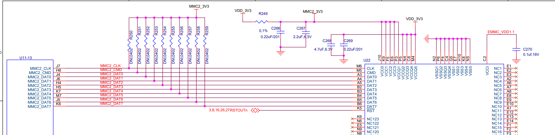
Where sd card is at mmc1 & emmc is at mmc2.
modified config gile & am57xx_evm.h file as per our requirement Here they are
#
# Automatically generated file; DO NOT EDIT.
# U-Boot 2018.01 Configuration
#
CONFIG_CREATE_ARCH_SYMLINK=y
# CONFIG_ARC is not set
CONFIG_ARM=y
# CONFIG_M68K is not set
# CONFIG_MICROBLAZE is not set
# CONFIG_MIPS is not set
# CONFIG_NDS32 is not set
# CONFIG_NIOS2 is not set
# CONFIG_PPC is not set
# CONFIG_SANDBOX is not set
# CONFIG_SH is not set
# CONFIG_X86 is not set
# CONFIG_XTENSA is not set
CONFIG_SYS_ARCH="arm"
CONFIG_SYS_CPU="armv7"
CONFIG_SYS_SOC="omap5"
CONFIG_SYS_VENDOR="ti"
CONFIG_SYS_BOARD="am57xx"
CONFIG_SYS_CONFIG_NAME="am57xx_evm"

#
# ARM architecture
#
CONFIG_HAS_VBAR=y
CONFIG_HAS_THUMB2=y
CONFIG_ARM_ASM_UNIFIED=y
CONFIG_SYS_ARM_CACHE_CP15=y
CONFIG_SYS_ARM_MMU=y
# CONFIG_SYS_ARM_MPU is not set
CONFIG_ARM_ERRATA_798870=y
CONFIG_ARM_CORTEX_A15_CVE_2017_5715=y
CONFIG_CPU_V7A=y
CONFIG_SYS_ARM_ARCH=7
CONFIG_SYS_CACHE_SHIFT_6=y
CONFIG_SYS_CACHELINE_SIZE=64
# CONFIG_ARM_SMCCC is not set
# CONFIG_SEMIHOSTING is not set
CONFIG_SYS_THUMB_BUILD=y
CONFIG_SPL_SYS_THUMB_BUILD=y
# CONFIG_SYS_L2CACHE_OFF is not set
# CONFIG_ENABLE_ARM_SOC_BOOT0_HOOK is not set
# CONFIG_ARM_CORTEX_CPU_IS_UP is not set
CONFIG_USE_ARCH_MEMCPY=y
CONFIG_SPL_USE_ARCH_MEMCPY=y
CONFIG_USE_ARCH_MEMSET=y
CONFIG_SPL_USE_ARCH_MEMSET=y
# CONFIG_ARM64_SUPPORT_AARCH32 is not set
# CONFIG_ARCH_AT91 is not set
# CONFIG_TARGET_EDB93XX is not set
# CONFIG_TARGET_ASPENITE is not set
# CONFIG_TARGET_GPLUGD is not set
# CONFIG_ARCH_DAVINCI is not set
# CONFIG_KIRKWOOD is not set
# CONFIG_ARCH_MVEBU is not set
# CONFIG_TARGET_DEVKIT3250 is not set
# CONFIG_TARGET_WORK_92105 is not set
# CONFIG_TARGET_APF27 is not set
# CONFIG_TARGET_APX4DEVKIT is not set
# CONFIG_TARGET_XFI3 is not set
# CONFIG_TARGET_M28EVK is not set
# CONFIG_TARGET_MX23EVK is not set
# CONFIG_TARGET_MX28EVK is not set
# CONFIG_TARGET_MX23_OLINUXINO is not set
# CONFIG_TARGET_BG0900 is not set
# CONFIG_TARGET_SANSA_FUZE_PLUS is not set
# CONFIG_TARGET_SC_SPS_1 is not set
# CONFIG_ORION5X is not set
# CONFIG_TARGET_SPEAR300 is not set
# CONFIG_TARGET_SPEAR310 is not set
# CONFIG_TARGET_SPEAR320 is not set
# CONFIG_TARGET_SPEAR600 is not set
# CONFIG_TARGET_STV0991 is not set
# CONFIG_TARGET_X600 is not set
# CONFIG_TARGET_IMX31_PHYCORE is not set
# CONFIG_TARGET_IMX31_PHYCORE_EET is not set
# CONFIG_TARGET_MX31ADS is not set
# CONFIG_TARGET_MX31PDK is not set
# CONFIG_TARGET_WOODBURN is not set
# CONFIG_TARGET_WOODBURN_SD is not set
# CONFIG_TARGET_FLEA3 is not set
# CONFIG_TARGET_MX35PDK is not set
# CONFIG_ARCH_BCM283X is not set
# CONFIG_TARGET_VEXPRESS_CA15_TC2 is not set
# CONFIG_TARGET_VEXPRESS_CA5X2 is not set
# CONFIG_TARGET_VEXPRESS_CA9X4 is not set
# CONFIG_TARGET_BCM23550_W1D is not set
# CONFIG_TARGET_BCM28155_AP is not set
# CONFIG_TARGET_BCMCYGNUS is not set
# CONFIG_TARGET_BCMNSP is not set
# CONFIG_TARGET_BCMNS2 is not set
# CONFIG_ARCH_EXYNOS is not set
# CONFIG_ARCH_S5PC1XX is not set
# CONFIG_ARCH_HIGHBANK is not set
# CONFIG_ARCH_INTEGRATOR is not set
# CONFIG_ARCH_KEYSTONE is not set
# CONFIG_ARCH_K3 is not set
CONFIG_ARCH_OMAP2PLUS=y
# CONFIG_ARCH_MESON is not set
# CONFIG_ARCH_MX25 is not set
# CONFIG_ARCH_MX7ULP is not set
# CONFIG_ARCH_MX7 is not set
# CONFIG_ARCH_MX6 is not set
CONFIG_SPL_LDSCRIPT="arch/arm/mach-omap2/u-boot-spl.lds"
# CONFIG_ARCH_MX5 is not set
# CONFIG_ARCH_QEMU is not set
# CONFIG_ARCH_RMOBILE is not set
# CONFIG_TARGET_S32V234EVB is not set
# CONFIG_ARCH_SNAPDRAGON is not set
# CONFIG_ARCH_SOCFPGA is not set
# CONFIG_ARCH_SUNXI is not set
# CONFIG_TARGET_TS4600 is not set
# CONFIG_ARCH_VF610 is not set
# CONFIG_ARCH_ZYNQ is not set
# CONFIG_ARCH_ZYNQMP is not set
# CONFIG_TEGRA is not set
# CONFIG_TARGET_VEXPRESS64_AEMV8A is not set
# CONFIG_TARGET_VEXPRESS64_BASE_FVP is not set
# CONFIG_TARGET_VEXPRESS64_BASE_FVP_DRAM is not set
# CONFIG_TARGET_VEXPRESS64_JUNO is not set
# CONFIG_TARGET_LS2080A_EMU is not set
# CONFIG_TARGET_LS2080A_SIMU is not set
# CONFIG_TARGET_LS1088AQDS is not set
# CONFIG_TARGET_LS2080AQDS is not set
# CONFIG_TARGET_LS2080ARDB is not set
# CONFIG_TARGET_LS2081ARDB is not set
# CONFIG_TARGET_HIKEY is not set
# CONFIG_TARGET_POPLAR is not set
# CONFIG_TARGET_LS1012AQDS is not set
# CONFIG_TARGET_LS1012ARDB is not set
# CONFIG_TARGET_LS1012AFRDM is not set
# CONFIG_TARGET_LS1088ARDB is not set
# CONFIG_TARGET_LS1021AQDS is not set
# CONFIG_TARGET_LS1021ATWR is not set
# CONFIG_TARGET_LS1021AIOT is not set
# CONFIG_TARGET_LS1043AQDS is not set
# CONFIG_TARGET_LS1043ARDB is not set
# CONFIG_TARGET_LS1046AQDS is not set
# CONFIG_TARGET_LS1046ARDB is not set
# CONFIG_TARGET_H2200 is not set
# CONFIG_TARGET_ZIPITZ2 is not set
# CONFIG_TARGET_COLIBRI_PXA270 is not set
# CONFIG_ARCH_UNIPHIER is not set
# CONFIG_STM32 is not set
# CONFIG_ARCH_STI is not set
# CONFIG_ARCH_ROCKCHIP is not set
# CONFIG_TARGET_THUNDERX_88XX is not set
# CONFIG_ARCH_ASPEED is not set
# CONFIG_TI_SECURE_DEVICE is not set
CONFIG_SYS_TEXT_BASE=0x80800000
CONFIG_TI_I2C_BOARD_DETECT=y
CONFIG_EEPROM_BUS_ADDRESS=0
CONFIG_EEPROM_CHIP_ADDRESS=0x50
CONFIG_TI_COMMON_CMD_OPTIONS=y
CONFIG_SPL_GPIO_SUPPORT=y
CONFIG_SPL_LIBCOMMON_SUPPORT=y
CONFIG_SPL_LIBGENERIC_SUPPORT=y
CONFIG_SYS_MALLOC_F_LEN=0x2000
# CONFIG_OMAP34XX is not set
# CONFIG_OMAP44XX is not set
CONFIG_OMAP54XX=y
# CONFIG_TI814X is not set
# CONFIG_TI816X is not set
# CONFIG_AM43XX is not set
# CONFIG_AM33XX is not set
CONFIG_SYS_MPUCLK=500
CONFIG_DRA7XX=y
# CONFIG_TARGET_CL_SOM_AM57X is not set
# CONFIG_TARGET_CM_T54 is not set
# CONFIG_TARGET_OMAP5_UEVM is not set
# CONFIG_TARGET_DRA7XX_EVM is not set
CONFIG_TARGET_AM57XX_EVM=y
CONFIG_OMAP_PLATFORM_RESET_TIME_MAX_USEC=31219

#
# Voltage Domain OPP selections
#
CONFIG_DRA7_MPU_OPP_NOM=y
# CONFIG_DRA7_DSPEVE_OPP_NOM is not set
# CONFIG_DRA7_DSPEVE_OPP_OD is not set
CONFIG_DRA7_DSPEVE_OPP_HIGH=y
# CONFIG_DRA7_IVA_OPP_NOM is not set
# CONFIG_DRA7_IVA_OPP_OD is not set
CONFIG_DRA7_IVA_OPP_HIGH=y
# CONFIG_DRA7_GPU_OPP_NOM is not set
# CONFIG_DRA7_GPU_OPP_OD is not set
CONFIG_DRA7_GPU_OPP_HIGH=y
CONFIG_CONS_INDEX=3
CONFIG_SPL_MMC_SUPPORT=y
CONFIG_SPL_SERIAL_SUPPORT=y
# CONFIG_SPL_DRIVERS_MISC_SUPPORT is not set
CONFIG_SPL_LIBDISK_SUPPORT=y
# CONFIG_SPL_NAND_SUPPORT is not set
# CONFIG_SPL_SPI_FLASH_SUPPORT is not set
# CONFIG_SPL_SPI_SUPPORT is not set
# CONFIG_SPL_WATCHDOG_SUPPORT is not set
CONFIG_IDENT_STRING=""
CONFIG_SPL_STACK_R_ADDR=0x82000000
CONFIG_SPL_FAT_SUPPORT=y
CONFIG_ARMV7_LPAE=y
# CONFIG_CMD_DEKBLOB is not set
# CONFIG_CMD_HDMIDETECT is not set

#
# ARM debug
#
# CONFIG_DEBUG_LL is not set
CONFIG_DEFAULT_DEVICE_TREE="am57xx-beagle-x15-revc"
CONFIG_SMBIOS_PRODUCT_NAME="am57xx"
# CONFIG_DEBUG_UART is not set
# CONFIG_AHCI is not set

#
# General setup
#
CONFIG_LOCALVERSION=""
CONFIG_LOCALVERSION_AUTO=y
CONFIG_CC_OPTIMIZE_FOR_SIZE=y
# CONFIG_DISTRO_DEFAULTS is not set
CONFIG_SYS_MALLOC_F=y
CONFIG_SPL_SYS_MALLOC_F_LEN=0x2000
CONFIG_TPL_SYS_MALLOC_F_LEN=0x2000
CONFIG_EXPERT=y
CONFIG_SYS_MALLOC_CLEAR_ON_INIT=y
# CONFIG_TOOLS_DEBUG is not set
# CONFIG_PHYS_64BIT is not set

#
# Boot images
#
# CONFIG_ANDROID_BOOT_IMAGE is not set
CONFIG_FIT=y
CONFIG_FIT_ENABLE_SHA256_SUPPORT=y
# CONFIG_FIT_SIGNATURE is not set
# CONFIG_FIT_VERBOSE is not set
# CONFIG_FIT_BEST_MATCH is not set
CONFIG_SPL_FIT=y
# CONFIG_SPL_FIT_SIGNATURE is not set
CONFIG_SPL_LOAD_FIT=y
# CONFIG_SPL_FIT_IMAGE_POST_PROCESS is not set
CONFIG_SPL_FIT_SOURCE=""
CONFIG_SPL_FIT_GENERATOR=""
CONFIG_OF_BOARD_SETUP=y
# CONFIG_OF_SYSTEM_SETUP is not set
# CONFIG_OF_STDOUT_VIA_ALIAS is not set
CONFIG_SYS_EXTRA_OPTIONS=""
CONFIG_ARCH_FIXUP_FDT_MEMORY=y

#
# API
#
# CONFIG_API is not set

#
# Boot timing
#
# CONFIG_BOOTSTAGE is not set
CONFIG_BOOTSTAGE_RECORD_COUNT=30
CONFIG_SPL_BOOTSTAGE_RECORD_COUNT=5
CONFIG_BOOTSTAGE_STASH_ADDR=0
CONFIG_BOOTSTAGE_STASH_SIZE=0x1000

#
# Boot media
#
# CONFIG_NAND_BOOT is not set
# CONFIG_ONENAND_BOOT is not set
# CONFIG_QSPI_BOOT is not set
# CONFIG_SATA_BOOT is not set
CONFIG_SD_BOOT=y
# CONFIG_SPI_BOOT is not set
CONFIG_BOOTDELAY=2
# CONFIG_USE_BOOTARGS is not set
# CONFIG_USE_BOOTCOMMAND is not set

#
# Console
#
# CONFIG_CONSOLE_RECORD is not set
CONFIG_LOGLEVEL=4
CONFIG_SPL_LOGLEVEL=4
# CONFIG_SILENT_CONSOLE is not set
# CONFIG_PRE_CONSOLE_BUFFER is not set
# CONFIG_CONSOLE_MUX is not set
# CONFIG_SYS_CONSOLE_IS_IN_ENV is not set
# CONFIG_SYS_CONSOLE_OVERWRITE_ROUTINE is not set
# CONFIG_SYS_CONSOLE_ENV_OVERWRITE is not set
CONFIG_SYS_CONSOLE_INFO_QUIET=y
# CONFIG_SYS_STDIO_DEREGISTER is not set

#
# Logging
#
# CONFIG_LOG is not set
# CONFIG_SPL_LOG is not set
CONFIG_DEFAULT_FDT_FILE=""
CONFIG_VERSION_VARIABLE=y
CONFIG_BOARD_LATE_INIT=y
CONFIG_DISPLAY_CPUINFO=y
CONFIG_DISPLAY_BOARDINFO=y

#
# Start-up hooks
#
# CONFIG_ARCH_EARLY_INIT_R is not set
# CONFIG_ARCH_MISC_INIT is not set
CONFIG_BOARD_EARLY_INIT_F=y

#
# Security support
#
CONFIG_HASH=y

#
# SPL / TPL
#
CONFIG_SUPPORT_SPL=y
CONFIG_SPL=y
CONFIG_SPL_BOARD_INIT=y
# CONFIG_SPL_BOOTROM_SUPPORT is not set
CONFIG_SPL_RAW_IMAGE_SUPPORT=y
CONFIG_SPL_LEGACY_IMAGE_SUPPORT=y
CONFIG_SPL_SYS_MALLOC_SIMPLE=y
# CONFIG_TPL_SYS_MALLOC_SIMPLE is not set
CONFIG_SPL_STACK_R=y
CONFIG_SPL_STACK_R_MALLOC_SIMPLE_LEN=0x100000
CONFIG_SPL_SEPARATE_BSS=y
# CONFIG_SPL_SKIP_CLEAR_BSS is not set
CONFIG_SPL_DISPLAY_PRINT=y
CONFIG_SYS_MMCSD_RAW_MODE_U_BOOT_USE_SECTOR=y
CONFIG_SYS_MMCSD_RAW_MODE_U_BOOT_SECTOR=0x300
# CONFIG_SYS_MMCSD_RAW_MODE_U_BOOT_USE_PARTITION is not set
# CONFIG_SPL_CRC32_SUPPORT is not set
# CONFIG_SPL_MD5_SUPPORT is not set
# CONFIG_SPL_SHA1_SUPPORT is not set
# CONFIG_SPL_SHA256_SUPPORT is not set
# CONFIG_SPL_FIT_IMAGE_TINY is not set
# CONFIG_SPL_CPU_SUPPORT is not set
# CONFIG_SPL_CRYPTO_SUPPORT is not set
# CONFIG_SPL_HASH_SUPPORT is not set
CONFIG_SPL_DMA_SUPPORT=y
CONFIG_SPL_ENV_SUPPORT=y
# CONFIG_SPL_SAVEENV is not set
# CONFIG_SPL_ETH_SUPPORT is not set
CONFIG_SPL_EXT_SUPPORT=y
# CONFIG_SPL_FPGA_SUPPORT is not set
CONFIG_SPL_I2C_SUPPORT=y
# CONFIG_SPL_MAILBOX_SUPPORT is not set
# CONFIG_SPL_MMC_WRITE is not set
# CONFIG_SPL_MPC8XXX_INIT_DDR_SUPPORT is not set
# CONFIG_SPL_MTD_SUPPORT is not set
# CONFIG_SPL_MUSB_NEW_SUPPORT is not set
# CONFIG_SPL_NET_SUPPORT is not set
# CONFIG_SPL_NO_CPU_SUPPORT is not set
# CONFIG_SPL_NOR_SUPPORT is not set
# CONFIG_SPL_XIP_SUPPORT is not set
# CONFIG_SPL_ONENAND_SUPPORT is not set
CONFIG_SPL_OS_BOOT=y
# CONFIG_SPL_PCI_SUPPORT is not set
# CONFIG_SPL_PCH_SUPPORT is not set
# CONFIG_SPL_POST_MEM_SUPPORT is not set
CONFIG_SPL_POWER_SUPPORT=y
# CONFIG_SPL_RAM_SUPPORT is not set
# CONFIG_SPL_REMOTEPROC_SUPPORT is not set
# CONFIG_SPL_RTC_SUPPORT is not set
# CONFIG_SPL_SATA_SUPPORT is not set
CONFIG_SPL_THERMAL=y
# CONFIG_SPL_USB_HOST_SUPPORT is not set
# CONFIG_SPL_USB_GADGET_SUPPORT is not set
# CONFIG_SPL_YMODEM_SUPPORT is not set

#
# Command line interface
#
CONFIG_CMDLINE=y
CONFIG_HUSH_PARSER=y
CONFIG_SYS_PROMPT="=> "

#
# Autoboot options
#
CONFIG_AUTOBOOT=y
# CONFIG_AUTOBOOT_KEYED is not set

#
# FASTBOOT
#

#
# Commands
#

#
# Info commands
#
CONFIG_CMD_BDI=y
# CONFIG_CMD_CONFIG is not set
CONFIG_CMD_CONSOLE=y
# CONFIG_CMD_CPU is not set
# CONFIG_CMD_LICENSE is not set

#
# Boot commands
#
CONFIG_CMD_BOOTD=y
CONFIG_CMD_BOOTM=y
CONFIG_CMD_BOOTZ=y
CONFIG_CMD_BOOTEFI=y
CONFIG_CMD_BOOTEFI_HELLO_COMPILE=y
# CONFIG_CMD_BOOTEFI_HELLO is not set
# CONFIG_CMD_BOOTEFI_SELFTEST is not set
# CONFIG_CMD_BOOTMENU is not set
CONFIG_CMD_ELF=y
CONFIG_CMD_FDT=y
CONFIG_CMD_GO=y
CONFIG_CMD_RUN=y
CONFIG_CMD_IMI=y
# CONFIG_CMD_IMLS is not set
CONFIG_CMD_XIMG=y
# CONFIG_CMD_POWEROFF is not set
CONFIG_CMD_SPL=y
CONFIG_CMD_SPL_NAND_OFS=0
CONFIG_CMD_SPL_WRITE_SIZE=0x2000
# CONFIG_CMD_THOR_DOWNLOAD is not set
# CONFIG_CMD_ZBOOT is not set

#
# Environment commands
#
CONFIG_CMD_ASKENV=y
CONFIG_CMD_EXPORTENV=y
CONFIG_CMD_IMPORTENV=y
CONFIG_CMD_EDITENV=y
# CONFIG_CMD_GREPENV is not set
CONFIG_CMD_SAVEENV=y
CONFIG_CMD_ENV_EXISTS=y
# CONFIG_CMD_ENV_CALLBACK is not set
# CONFIG_CMD_ENV_FLAGS is not set

#
# Memory commands
#
CONFIG_CMD_CRC32=y
# CONFIG_CRC32_VERIFY is not set
CONFIG_CMD_EEPROM=y
# CONFIG_CMD_EEPROM_LAYOUT is not set
# CONFIG_LOOPW is not set
# CONFIG_CMD_MD5SUM is not set
# CONFIG_CMD_MEMINFO is not set
CONFIG_CMD_MEMORY=y
# CONFIG_CMD_MEMTEST is not set
# CONFIG_CMD_MX_CYCLIC is not set
# CONFIG_CMD_SHA1SUM is not set
# CONFIG_CMD_STRINGS is not set

#
# Compression commands
#
# CONFIG_CMD_LZMADEC is not set
# CONFIG_CMD_UNZIP is not set
# CONFIG_CMD_ZIP is not set

#
# Device access commands
#
# CONFIG_CMD_ARMFLASH is not set
# CONFIG_CMD_CLK is not set
# CONFIG_CMD_DEMO is not set
# CONFIG_CMD_DFU is not set
CONFIG_CMD_DM=y
# CONFIG_CMD_FDC is not set
# CONFIG_CMD_FLASH is not set
CONFIG_CMD_FPGA=y
# CONFIG_CMD_FPGA_LOADBP is not set
# CONFIG_CMD_FPGA_LOADFS is not set
# CONFIG_CMD_FPGA_LOADMK is not set
# CONFIG_CMD_FPGA_LOADP is not set
# CONFIG_CMD_FPGAD is not set
# CONFIG_CMD_FUSE is not set
CONFIG_CMD_GPIO=y
CONFIG_CMD_GPT=y
CONFIG_RANDOM_UUID=y
# CONFIG_CMD_GPT_RENAME is not set
# CONFIG_CMD_IDE is not set
# CONFIG_CMD_IO is not set
# CONFIG_CMD_IOTRACE is not set
CONFIG_CMD_I2C=y
CONFIG_CMD_LOADB=y
CONFIG_CMD_LOADS=y
CONFIG_CMD_MMC=y
# CONFIG_CMD_NAND is not set
# CONFIG_CMD_MMC_SPI is not set
# CONFIG_CMD_ONENAND is not set
CONFIG_CMD_PART=y
# CONFIG_CMD_PCI is not set
# CONFIG_CMD_PCMCIA is not set
# CONFIG_CMD_READ is not set
# CONFIG_CMD_SATA is not set
# CONFIG_CMD_SAVES is not set
# CONFIG_CMD_SDRAM is not set
# CONFIG_CMD_SF is not set
# CONFIG_CMD_SF_TEST is not set
# CONFIG_CMD_SPI is not set
# CONFIG_CMD_TSI148 is not set
# CONFIG_CMD_UNIVERSE is not set
# CONFIG_CMD_USB is not set
# CONFIG_CMD_USB_SDP is not set
# CONFIG_CMD_USB_MASS_STORAGE is not set

#
# Shell scripting commands
#
CONFIG_CMD_ECHO=y
CONFIG_CMD_ITEST=y
CONFIG_CMD_SOURCE=y
# CONFIG_CMD_SETEXPR is not set

#
# Network commands
#
CONFIG_CMD_NET=y
# CONFIG_CMD_TFTPPUT is not set
# CONFIG_CMD_TFTPSRV is not set
# CONFIG_CMD_RARP is not set
CONFIG_CMD_DHCP=y
# CONFIG_CMD_PXE is not set
CONFIG_CMD_NFS=y
CONFIG_CMD_MII=y
CONFIG_CMD_PING=y
# CONFIG_CMD_CDP is not set
# CONFIG_CMD_SNTP is not set
# CONFIG_CMD_DNS is not set
# CONFIG_CMD_LINK_LOCAL is not set
# CONFIG_CMD_ETHSW is not set

#
# Misc commands
#
# CONFIG_CMD_BSP is not set
# CONFIG_CMD_BKOPS_ENABLE is not set
# CONFIG_CMD_CACHE is not set
# CONFIG_CMD_DISPLAY is not set
# CONFIG_CMD_LED is not set
# CONFIG_CMD_DATE is not set
CONFIG_CMD_TIME=y
# CONFIG_CMD_GETTIME is not set
CONFIG_CMD_MISC=y
# CONFIG_CMD_TIMER is not set
# CONFIG_CMD_QFW is not set
# CONFIG_CMD_TERMINAL is not set
# CONFIG_CMD_UUID is not set

#
# TI specific command line interface
#
CONFIG_CMD_DDR3=y

#
# Power commands
#
# CONFIG_CMD_PMIC is not set
CONFIG_CMD_REGULATOR=y

#
# Security commands
#
# CONFIG_CMD_AES is not set
# CONFIG_CMD_BLOB is not set
# CONFIG_CMD_HASH is not set

#
# Firmware commands
#

#
# Filesystem commands
#
# CONFIG_CMD_BTRFS is not set
CONFIG_CMD_EXT2=y
CONFIG_CMD_EXT4=y
CONFIG_CMD_EXT4_WRITE=y
CONFIG_CMD_FAT=y
CONFIG_CMD_FS_GENERIC=y
# CONFIG_CMD_FS_UUID is not set
# CONFIG_CMD_JFFS2 is not set
# CONFIG_CMD_MTDPARTS is not set
# CONFIG_CMD_REISER is not set
# CONFIG_CMD_SCSI is not set
# CONFIG_CMD_ZFS is not set

#
# Debug commands
#
# CONFIG_CMD_BEDBUG is not set
# CONFIG_CMD_DIAG is not set
# CONFIG_CMD_KGDB is not set
# CONFIG_CMD_LOG is not set
# CONFIG_CMD_TRACE is not set
# CONFIG_CMD_UBI is not set

#
# Partition Types
#
CONFIG_PARTITIONS=y
# CONFIG_MAC_PARTITION is not set
# CONFIG_SPL_MAC_PARTITION is not set
CONFIG_DOS_PARTITION=y
CONFIG_SPL_DOS_PARTITION=y
CONFIG_ISO_PARTITION=y
CONFIG_SPL_ISO_PARTITION=y
# CONFIG_AMIGA_PARTITION is not set
# CONFIG_SPL_AMIGA_PARTITION is not set
CONFIG_EFI_PARTITION=y
CONFIG_EFI_PARTITION_ENTRIES_NUMBERS=128
CONFIG_EFI_PARTITION_ENTRIES_OFF=0
CONFIG_SPL_EFI_PARTITION=y
CONFIG_PARTITION_UUIDS=y
CONFIG_SPL_PARTITION_UUIDS=y
# CONFIG_PARTITION_TYPE_GUID is not set
CONFIG_SUPPORT_OF_CONTROL=y
CONFIG_DTC=y

#
# Device Tree Control
#
CONFIG_OF_CONTROL=y
# CONFIG_OF_BOARD_FIXUP is not set
CONFIG_SPL_OF_CONTROL=y
# CONFIG_OF_LIVE is not set
CONFIG_OF_SEPARATE=y
# CONFIG_OF_EMBED is not set
# CONFIG_OF_BOARD is not set
CONFIG_OF_LIST="am57xx-beagle-x15-revc"
# CONFIG_MULTI_DTB_FIT is not set
# CONFIG_SPL_MULTI_DTB_FIT is not set
CONFIG_OF_SPL_REMOVE_PROPS="pinctrl-0 pinctrl-names clocks clock-names interrupt-parent"
# CONFIG_SPL_OF_PLATDATA is not set
CONFIG_MKIMAGE_DTC_PATH="dtc"

#
# Environment
#
# CONFIG_ENV_IS_NOWHERE is not set
# CONFIG_ENV_IS_IN_EEPROM is not set
# CONFIG_ENV_IS_IN_FAT is not set
# CONFIG_ENV_IS_IN_FLASH is not set
CONFIG_ENV_IS_IN_MMC=y
# CONFIG_ENV_IS_IN_NAND is not set
# CONFIG_ENV_IS_IN_NVRAM is not set
# CONFIG_ENV_IS_IN_ONENAND is not set
# CONFIG_ENV_IS_IN_REMOTE is not set
# CONFIG_ENV_IS_IN_SPI_FLASH is not set
# CONFIG_ENV_IS_IN_UBI is not set
CONFIG_NET=y
# CONFIG_NET_RANDOM_ETHADDR is not set
# CONFIG_NETCONSOLE is not set
CONFIG_NET_TFTP_VARS=y
CONFIG_BOOTP_PXE_CLIENTARCH=0x15
CONFIG_BOOTP_VCI_STRING="U-Boot.armv7"

#
# Device Drivers
#

#
# Generic Driver Options
#
CONFIG_DM=y
CONFIG_SPL_DM=y
CONFIG_DM_WARN=y
# CONFIG_DM_DEBUG is not set
CONFIG_DM_DEVICE_REMOVE=y
CONFIG_DM_STDIO=y
CONFIG_DM_SEQ_ALIAS=y
# CONFIG_SPL_DM_SEQ_ALIAS is not set
CONFIG_REGMAP=y
# CONFIG_SPL_REGMAP is not set
CONFIG_SYSCON=y
# CONFIG_DEVRES is not set
CONFIG_SIMPLE_BUS=y
CONFIG_SPL_SIMPLE_BUS=y
CONFIG_OF_TRANSLATE=y
# CONFIG_SPL_OF_TRANSLATE is not set
CONFIG_DM_DEV_READ_INLINE=y
# CONFIG_ADC is not set
# CONFIG_ADC_EXYNOS is not set
# CONFIG_ADC_SANDBOX is not set
# CONFIG_SARADC_ROCKCHIP is not set
# CONFIG_SATA is not set
# CONFIG_SCSI_AHCI is not set

#
# SATA/SCSI device support
#
# CONFIG_DWC_AHSATA is not set
# CONFIG_FSL_SATA is not set
# CONFIG_MVSATA_IDE is not set
# CONFIG_SATA_MV is not set
# CONFIG_SATA_SIL is not set
# CONFIG_SATA_SIL3114 is not set
# CONFIG_BLK is not set
# CONFIG_IDE is not set

#
# Boot count support
#
# CONFIG_BOOTCOUNT is not set

#
# Clock
#
# CONFIG_CLK is not set
# CONFIG_CPU is not set

#
# Hardware crypto devices
#
# CONFIG_FSL_CAAM is not set
# CONFIG_SYS_FSL_SEC_BE is not set
# CONFIG_SYS_FSL_SEC_LE is not set

#
# Demo for driver model
#
# CONFIG_DM_DEMO is not set

#
# DFU support
#

#
# DMA Support
#
# CONFIG_DMA is not set
# CONFIG_TI_EDMA3 is not set

#
# FPGA support
#
# CONFIG_FPGA_ALTERA is not set
# CONFIG_FPGA_SOCFPGA is not set
# CONFIG_FPGA_XILINX is not set

#
# GPIO Support
#
CONFIG_DM_GPIO=y
# CONFIG_ALTERA_PIO is not set
# CONFIG_DWAPB_GPIO is not set
# CONFIG_AT91_GPIO is not set
# CONFIG_ATMEL_PIO4 is not set
# CONFIG_DA8XX_GPIO is not set
# CONFIG_INTEL_BROADWELL_GPIO is not set
# CONFIG_INTEL_ICH6_GPIO is not set
# CONFIG_IMX_RGPIO2P is not set
# CONFIG_HSDK_CREG_GPIO is not set
# CONFIG_LPC32XX_GPIO is not set
# CONFIG_MSM_GPIO is not set
CONFIG_OMAP_GPIO=y
# CONFIG_CMD_PCA953X is not set
# CONFIG_PCF8575_GPIO is not set
# CONFIG_ROCKCHIP_GPIO is not set
# CONFIG_CMD_TCA642X is not set
# CONFIG_TEGRA_GPIO is not set
# CONFIG_TEGRA186_GPIO is not set
# CONFIG_VYBRID_GPIO is not set
# CONFIG_DM_74X164 is not set
# CONFIG_DM_PCA953X is not set
# CONFIG_MPC85XX_GPIO is not set

#
# I2C support
#
CONFIG_DM_I2C=y
# CONFIG_DM_I2C_COMPAT is not set
# CONFIG_I2C_SET_DEFAULT_BUS_NUM is not set
# CONFIG_DM_I2C_GPIO is not set
# CONFIG_SYS_I2C_FSL is not set
# CONFIG_SYS_I2C_DW is not set
# CONFIG_SYS_I2C_INTEL is not set
# CONFIG_SYS_I2C_IMX_LPI2C is not set
CONFIG_SYS_I2C_OMAP24XX=y
# CONFIG_SYS_I2C_ROCKCHIP is not set
# CONFIG_SYS_I2C_MVTWSI is not set
CONFIG_SYS_I2C_BUS_MAX=5
# CONFIG_I2C_MUX is not set
# CONFIG_DM_KEYBOARD is not set
# CONFIG_CROS_EC_KEYB is not set

#
# LED Support
#
# CONFIG_LED is not set
# CONFIG_SPL_LED is not set
# CONFIG_LED_STATUS is not set

#
# Mailbox Controller Support
#
# CONFIG_DM_MAILBOX is not set

#
# Memory Controller drivers
#

#
# Multifunction device drivers
#
CONFIG_MISC=y
# CONFIG_ALTERA_SYSID is not set
# CONFIG_ATSHA204A is not set
# CONFIG_ROCKCHIP_EFUSE is not set
# CONFIG_CROS_EC is not set
# CONFIG_DS4510 is not set
# CONFIG_FSL_SEC_MON is not set
# CONFIG_MXC_OCOTP is not set
# CONFIG_NUVOTON_NCT6102D is not set
# CONFIG_PWRSEQ is not set
# CONFIG_PCA9551_LED is not set
# CONFIG_WINBOND_W83627 is not set
# CONFIG_I2C_EEPROM is not set
# CONFIG_SPL_I2C_EEPROM is not set

#
# MMC Host controller Support
#
CONFIG_MMC=y
CONFIG_MMC_WRITE=y
# CONFIG_MMC_BROKEN_CD is not set
CONFIG_DM_MMC=y
CONFIG_SPL_DM_MMC=y
# CONFIG_ARM_PL180_MMCI is not set
CONFIG_MMC_QUIRKS=y
CONFIG_MMC_HW_PARTITIONING=y
CONFIG_MMC_IO_VOLTAGE=y
# CONFIG_SPL_MMC_IO_VOLTAGE is not set
CONFIG_MMC_UHS_SUPPORT=y
# CONFIG_MMC_HS400_SUPPORT is not set
# CONFIG_SPL_MMC_HS400_SUPPORT is not set
# CONFIG_MMC_HS200_SUPPORT is not set
# CONFIG_SPL_MMC_HS200_SUPPORT is not set
CONFIG_MMC_VERBOSE=y
# CONFIG_SPL_MMC_TINY is not set
# CONFIG_MMC_DW is not set
# CONFIG_MMC_MXC is not set
# CONFIG_MMC_MXS is not set
# CONFIG_MMC_PCI is not set
CONFIG_MMC_OMAP_HS=y
# CONFIG_MMC_SDHCI is not set
# CONFIG_FTSDC010 is not set

#
# MTD Support
#
# CONFIG_MTD is not set
# CONFIG_MTD_NOR_FLASH is not set
# CONFIG_NAND is not set

#
# SPI Flash Support
#
# CONFIG_SPI_FLASH is not set

#
# UBI support
#
# CONFIG_MTD_UBI is not set
# CONFIG_BITBANGMII is not set
# CONFIG_MV88E6352_SWITCH is not set
CONFIG_PHYLIB=y
# CONFIG_MV88E61XX_SWITCH is not set
# CONFIG_PHYLIB_10G is not set
# CONFIG_PHY_AQUANTIA is not set
# CONFIG_PHY_ATHEROS is not set
# CONFIG_PHY_BROADCOM is not set
# CONFIG_PHY_CORTINA is not set
# CONFIG_PHY_DAVICOM is not set
# CONFIG_PHY_ET1011C is not set
# CONFIG_PHY_LXT is not set
# CONFIG_PHY_MARVELL is not set
# CONFIG_PHY_MESON_GXL is not set
CONFIG_PHY_MICREL=y
CONFIG_PHY_MICREL_KSZ90X1=y
# CONFIG_PHY_MICREL_KSZ8XXX is not set
# CONFIG_PHY_MSCC is not set
# CONFIG_PHY_NATSEMI is not set
# CONFIG_PHY_REALTEK is not set
# CONFIG_PHY_SMSC is not set
# CONFIG_PHY_TERANETICS is not set
# CONFIG_PHY_TI is not set
# CONFIG_PHY_VITESSE is not set
# CONFIG_PHY_XILINX is not set
# CONFIG_PHY_FIXED is not set
CONFIG_DM_ETH=y
CONFIG_NETDEVICES=y
CONFIG_PHY_GIGE=y
# CONFIG_ALTERA_TSE is not set
# CONFIG_BCM_SF2_ETH is not set
# CONFIG_DWC_ETH_QOS is not set
# CONFIG_E1000 is not set
# CONFIG_ETH_DESIGNWARE is not set
# CONFIG_ETHOC is not set
# CONFIG_FTMAC100 is not set
# CONFIG_MACB is not set
# CONFIG_RGMII is not set
# CONFIG_RTL8139 is not set
# CONFIG_RTL8169 is not set
# CONFIG_SMC911X is not set
# CONFIG_SUN7I_GMAC is not set
# CONFIG_SUN4I_EMAC is not set
# CONFIG_SUN8I_EMAC is not set
# CONFIG_PCI is not set

#
# PHY Subsystem
#
CONFIG_PHY=y
# CONFIG_SPL_PHY is not set
# CONFIG_NOP_PHY is not set
CONFIG_PIPE3_PHY=y
CONFIG_OMAP_USB2_PHY=y
# CONFIG_AM654_MMC_PHY is not set
# CONFIG_MVEBU_COMPHY_SUPPORT is not set

#
# Pin controllers
#
# CONFIG_PINCTRL is not set
# CONFIG_SPL_PINCTRL is not set

#
# Power
#

#
# Power Domain Support
#
# CONFIG_POWER_DOMAIN is not set
CONFIG_DM_PMIC=y
CONFIG_PMIC_CHILDREN=y
CONFIG_SPL_PMIC_CHILDREN=y
# CONFIG_PMIC_ACT8846 is not set
# CONFIG_PMIC_AS3722 is not set
# CONFIG_DM_PMIC_PFUZE100 is not set
# CONFIG_DM_PMIC_MAX77686 is not set
# CONFIG_DM_PMIC_MAX8998 is not set
# CONFIG_PMIC_MAX8997 is not set
# CONFIG_PMIC_PM8916 is not set
# CONFIG_PMIC_RK8XX is not set
# CONFIG_PMIC_S2MPS11 is not set
# CONFIG_DM_PMIC_SANDBOX is not set
# CONFIG_PMIC_S5M8767 is not set
# CONFIG_PMIC_RN5T567 is not set
# CONFIG_PMIC_TPS65090 is not set
CONFIG_PMIC_PALMAS=y
# CONFIG_PMIC_LP873X is not set
# CONFIG_PMIC_LP87565 is not set
# CONFIG_POWER_MC34VR500 is not set
# CONFIG_DM_PMIC_TPS65910 is not set
CONFIG_DM_REGULATOR=y
# CONFIG_SPL_DM_REGULATOR is not set
# CONFIG_REGULATOR_PWM is not set
# CONFIG_DM_REGULATOR_FIXED is not set
# CONFIG_DM_REGULATOR_GPIO is not set
CONFIG_DM_REGULATOR_PALMAS=y
CONFIG_DM_REGULATOR_PBIAS=y
# CONFIG_DM_PWM is not set
# CONFIG_PWM_SANDBOX is not set
# CONFIG_RAM is not set

#
# Remote Processor drivers
#

#
# Reset Controller Support
#
# CONFIG_DM_RESET is not set

#
# Real Time Clock
#
# CONFIG_DM_RTC is not set
# CONFIG_RTC_S35392A is not set
# CONFIG_SCSI is not set

#
# Serial drivers
#
CONFIG_BAUDRATE=115200
CONFIG_REQUIRE_SERIAL_CONSOLE=y
CONFIG_SERIAL_PRESENT=y
CONFIG_SPL_SERIAL_PRESENT=y
CONFIG_DM_SERIAL=y
# CONFIG_SERIAL_RX_BUFFER is not set
CONFIG_SPL_DM_SERIAL=y
# CONFIG_TPL_DM_SERIAL is not set
# CONFIG_DEBUG_UART_SKIP_INIT is not set
# CONFIG_ALTERA_JTAG_UART is not set
# CONFIG_ALTERA_UART is not set
# CONFIG_ATMEL_USART is not set
# CONFIG_FSL_LPUART is not set
# CONFIG_MVEBU_A3700_UART is not set
# CONFIG_NULLDEV_SERIAL is not set
CONFIG_SYS_NS16550=y
# CONFIG_MSM_SERIAL is not set
# CONFIG_PXA_SERIAL is not set

#
# Sound support
#
# CONFIG_SOUND is not set

#
# SOC (System On Chip) specific Drivers
#
# CONFIG_SOC_TI is not set

#
# SPI Support
#
# CONFIG_DM_SPI is not set
# CONFIG_SOFT_SPI is not set
# CONFIG_FSL_ESPI is not set
# CONFIG_FSL_QSPI is not set
# CONFIG_ATCSPI200_SPI is not set
# CONFIG_TI_QSPI is not set
# CONFIG_OMAP3_SPI is not set

#
# SPMI support
#
# CONFIG_SPMI is not set

#
# System reset device drivers
#
# CONFIG_SYSRESET is not set
# CONFIG_SYSRESET_SYSCON is not set
# CONFIG_SYSRESET_WATCHDOG is not set
CONFIG_DM_THERMAL=y
CONFIG_TI_DRA7_THERMAL=y

#
# Timer Support
#
# CONFIG_TIMER is not set

#
# TPM support
#
# CONFIG_USB is not set

#
# Graphics support
#
# CONFIG_DM_VIDEO is not set
# CONFIG_SYS_WHITE_ON_BLACK is not set
# CONFIG_NO_FB_CLEAR is not set

#
# TrueType Fonts
#
# CONFIG_VIDEO_VESA is not set
# CONFIG_VIDEO_LCD_ANX9804 is not set
# CONFIG_VIDEO_LCD_SSD2828 is not set
# CONFIG_VIDEO_MVEBU is not set
# CONFIG_I2C_EDID is not set
# CONFIG_DISPLAY is not set
# CONFIG_VIDEO_TEGRA20 is not set
# CONFIG_VIDEO_BRIDGE is not set
# CONFIG_VIDEO is not set
# CONFIG_LCD is not set
# CONFIG_VIDEO_SIMPLE is not set
# CONFIG_VIDEO_DT_SIMPLEFB is not set

#
# Watchdog Timer Support
#
# CONFIG_BCM2835_WDT is not set
# CONFIG_OMAP_WATCHDOG is not set
# CONFIG_ULP_WATCHDOG is not set
# CONFIG_WDT is not set
# CONFIG_PHYS_TO_BUS is not set

#
# File systems
#
# CONFIG_FS_BTRFS is not set
# CONFIG_FS_CBFS is not set
CONFIG_FS_FAT=y
CONFIG_FAT_WRITE=y
CONFIG_FS_FAT_MAX_CLUSTSIZE=65536
# CONFIG_FS_JFFS2 is not set
# CONFIG_FS_CRAMFS is not set
# CONFIG_YAFFS2 is not set

#
# Library routines
#
# CONFIG_BCH is not set
# CONFIG_CC_OPTIMIZE_LIBS_FOR_SPEED is not set
# CONFIG_DYNAMIC_CRC_TABLE is not set
CONFIG_HAVE_PRIVATE_LIBGCC=y
CONFIG_USE_PRIVATE_LIBGCC=y
CONFIG_SYS_HZ=1000
# CONFIG_USE_TINY_PRINTF is not set
# CONFIG_PANIC_HANG is not set
CONFIG_REGEX=y
# CONFIG_LIB_RAND is not set
# CONFIG_SPL_TINY_MEMSET is not set
# CONFIG_TPL_TINY_MEMSET is not set
# CONFIG_BITREVERSE is not set
# CONFIG_CMD_DHRYSTONE is not set

#
# Security support
#
# CONFIG_AES is not set
# CONFIG_RSA is not set
# CONFIG_TPM is not set

#
# Hashing Support
#
CONFIG_SHA1=y
CONFIG_SHA256=y
# CONFIG_SHA_HW_ACCEL is not set
CONFIG_MD5=y

#
# Compression Support
#
# CONFIG_LZ4 is not set
# CONFIG_LZMA is not set
# CONFIG_LZO is not set
# CONFIG_SPL_LZO is not set
# CONFIG_SPL_GZIP is not set
# CONFIG_ERRNO_STR is not set
CONFIG_OF_LIBFDT=y
CONFIG_OF_LIBFDT_OVERLAY=y
CONFIG_SPL_OF_LIBFDT=y
# CONFIG_FDT_FIXUP_PARTITIONS is not set

#
# System tables
#
CONFIG_GENERATE_SMBIOS_TABLE=y
CONFIG_SMBIOS_MANUFACTURER="ti"
CONFIG_EFI_LOADER=y
# CONFIG_UNIT_TEST is not set
sd boot works as expected
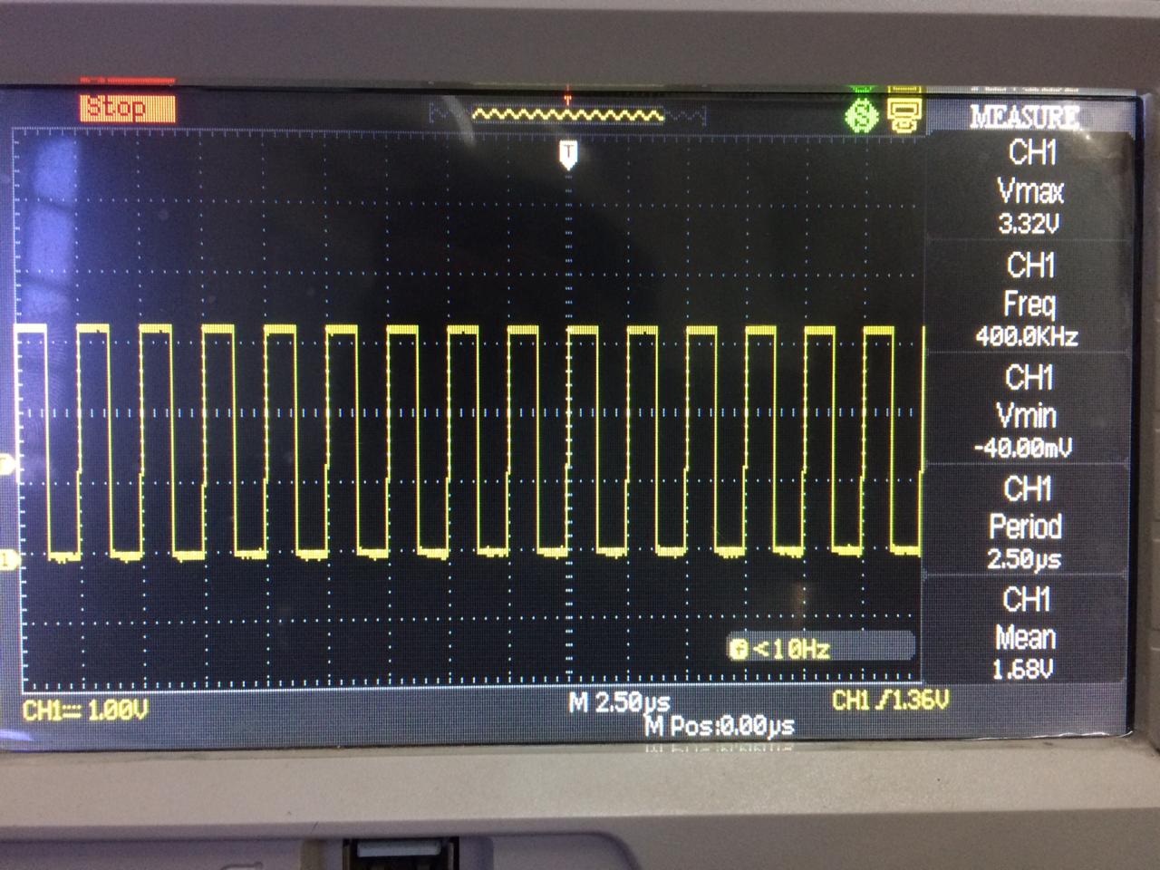
but emmc interface showing only 1-bit bus mode.
command output at uboot prompt are
=> mmc dev 1
switch to partitions #0, OK
mmc1(part 0) is current device
=> mmcinfo
Device: OMAP SD/MMC
Manufacturer ID: 9d
OEM: 101
Name: IS004
Bus Speed: 48000000
Mode : MMC High Speed (52MHz)
Rd Block Len: 512
MMC version 5.0
High Capacity: Yes
Capacity: 3.6 GiB
Bus Width: 1-bit
Erase Group Size: 512 KiB
HC WP Group Size: 8 MiB
User Capacity: 3.6 GiB WRREL
Boot Capacity: 2 MiB ENH
RPMB Capacity: 512 KiB ENH
Here is full boot log
U-Boot SPL 2018.01 (May 27 2019 - 17:18:07)
DRA752-GP ES2.0
Trying to boot from MMC1
omap_hsmmc_get_pinctrl_by_mode() --> mode : default node : 0xc38 mmc->dev:mmc@4809c000
fail to find default mode FDT_ERR_NOTFOUND
no pinctrl state for default mode
omap_hsmmc_get_pinctrl_by_mode() --> mode : default node : 0xe24 mmc->dev:mmc@480b4000
fail to find default mode FDT_ERR_NOTFOUND
no pinctrl state for default mode
*** Warning - bad CRC, using default environment


U-Boot 2018.01 (May 27 2019 - 17:18:07 +0530)

CPU  : DRA752-GP ES2.0
Model: TI AM5728 BeagleBoard-X15 rev C
Board: BeagleBoard X15 REV
DRAM:  1 GiB
MMC:   omap_hsmmc_get_pinctrl_by_mode() --> mode : default node : 0x1001c mmc->dev:mmc@4809c000
omap_hsmmc_get_pinctrl_by_mode() --> prop_name :pinctrl-0
omap_hsmmc_get_pinctrl_by_mode() <--
omap_hsmmc_get_pinctrl_by_mode() --> mode : sdr104 node : 0x1001c mmc->dev:mmc@4809c000
omap_hsmmc_get_pinctrl_by_mode() --> prop_name :pinctrl-6
omap_hsmmc_get_pinctrl_by_mode() <--
omap_hsmmc_get_pinctrl_by_mode() --> mode : sdr50 node : 0x1001c mmc->dev:mmc@4809c000
omap_hsmmc_get_pinctrl_by_mode() --> prop_name :pinctrl-4
omap_hsmmc_get_pinctrl_by_mode() <--
omap_hsmmc_get_pinctrl_by_mode() --> mode : ddr50 node : 0x1001c mmc->dev:mmc@4809c000
omap_hsmmc_get_pinctrl_by_mode() --> prop_name :pinctrl-5
omap_hsmmc_get_pinctrl_by_mode() <--
omap_hsmmc_get_pinctrl_by_mode() --> mode : sdr25 node : 0x1001c mmc->dev:mmc@4809c000
omap_hsmmc_get_pinctrl_by_mode() --> prop_name :pinctrl-3
omap_hsmmc_get_pinctrl_by_mode() <--
omap_hsmmc_get_pinctrl_by_mode() --> mode : sdr12 node : 0x1001c mmc->dev:mmc@4809c000
omap_hsmmc_get_pinctrl_by_mode() --> prop_name :pinctrl-2
omap_hsmmc_get_pinctrl_by_mode() <--
omap_hsmmc_get_pinctrl_by_mode() --> mode : hs node : 0x1001c mmc->dev:mmc@4809c000
omap_hsmmc_get_pinctrl_by_mode() --> prop_name :pinctrl-1
omap_hsmmc_get_pinctrl_by_mode() <--
omap_hsmmc_get_pinctrl_by_mode() --> mode : default node : 0x10250 mmc->dev:mmc@480b4000
omap_hsmmc_get_pinctrl_by_mode() --> prop_name :pinctrl-0
omap_hsmmc_get_pinctrl_by_mode() <--
omap_hsmmc_get_pinctrl_by_mode() --> mode : hs node : 0x10250 mmc->dev:mmc@480b4000
omap_hsmmc_get_pinctrl_by_mode() --> prop_name :pinctrl-1
omap_hsmmc_get_pinctrl_by_mode() <--
OMAP SD/MMC: 0, OMAP SD/MMC: 1
*** Warning - bad CRC, using default environment

Net:
Warning: ethernet@48484000 using MAC address from ROM
eth0: ethernet@48484000
Hit any key to stop autoboot:  0
=> mmc dev 1
switch to partitions #0, OK
mmc1(part 0) is current device
=> mmcinfo
Device: OMAP SD/MMC
Manufacturer ID: 9d
OEM: 101
Name: IS004
Bus Speed: 48000000
Mode : MMC High Speed (52MHz)
Rd Block Len: 512
MMC version 5.0
High Capacity: Yes
Capacity: 3.6 GiB
Bus Width: 1-bit
Erase Group Size: 512 KiB
HC WP Group Size: 8 MiB
User Capacity: 3.6 GiB WRREL
Boot Capacity: 2 MiB ENH
RPMB Capacity: 512 KiB ENH
=>
=> boot
switch to partitions #0, OK
mmc0 is current device
SD/MMC found on device 0
** Unable to read file boot.scr **
698 bytes read in 6 ms (113.3 KiB/s)
Loaded env from uEnv.txt
Importing environment from mmc0 ...
switch to partitions #0, OK
mmc0 is current device
SD/MMC found on device 0
3650048 bytes read in 190 ms (18.3 MiB/s)
98385 bytes read in 37 ms (2.5 MiB/s)
## Flattened Device Tree blob at 88000000
   Booting using the fdt blob at 0x88000000
   Loading Device Tree to 8ffe4000, end 8ffff050 ... OK

Starting kernel ...

[    0.000000] Booting Linux on physical CPU 0x0
[    0.000000] Linux version 4.14.79-gbde58ab01e (jigar@jigar) (gcc version 7.2.1 20171011 (Linaro GCC 7.2-2017.
11)) #3 SMP PREEMPT Fri May 24 12:16:06 IST 2019
[    0.000000] CPU: ARMv7 Processor [412fc0f2] revision 2 (ARMv7), cr=30c5387d
[    0.000000] CPU: div instructions available: patching division code
[    0.000000] CPU: PIPT / VIPT nonaliasing data cache, PIPT instruction cache
[    0.000000] OF: fdt: Machine model: TI AM5728 BeagleBoard-X15 rev C
[    0.000000] Memory policy: Data cache writealloc
[    0.000000] efi: Getting EFI parameters from FDT:
[    0.000000] efi: UEFI not found.
[    0.000000] Reserved memory: created CMA memory pool at 0x0000000095800000, size 56 MiB
[    0.000000] OF: reserved mem: initialized node ipu2-memory@95800000, compatible id shared-dma-pool
[    0.000000] Reserved memory: created CMA memory pool at 0x0000000099000000, size 64 MiB
[    0.000000] OF: reserved mem: initialized node dsp1-memory@99000000, compatible id shared-dma-pool
[    0.000000] Reserved memory: created CMA memory pool at 0x000000009d000000, size 32 MiB
[    0.000000] OF: reserved mem: initialized node ipu1-memory@9d000000, compatible id shared-dma-pool
[    0.000000] Reserved memory: created CMA memory pool at 0x000000009f000000, size 8 MiB
[    0.000000] OF: reserved mem: initialized node dsp2-memory@9f000000, compatible id shared-dma-pool
[    0.000000] cma: Reserved 24 MiB at 0x00000000be400000
[    0.000000] OMAP4: Map 0x00000000bfd00000 to fe600000 for dram barrier
[    0.000000] DRA752 ES2.0
[    0.000000] percpu: Embedded 15 pages/cpu @ef636000 s31308 r8192 d21940 u61440
[    0.000000] Built 1 zonelists, mobility grouping on.  Total pages: 259648
[    0.000000] Kernel command line: console=ttyO2,115200n8 root=PARTUUID=15c254dc-02 rw rootfstype=ext4 rootwait
[    0.000000] PID hash table entries: 4096 (order: 2, 16384 bytes)
[    0.000000] Dentry cache hash table entries: 131072 (order: 7, 524288 bytes)
[    0.000000] Inode-cache hash table entries: 65536 (order: 6, 262144 bytes)
[    0.000000] Memory: 831200K/1045504K available (8192K kernel code, 339K rwdata, 2320K rodata, 2048K init, 280
K bss, 25888K reserved, 188416K cma-reserved, 234496K highmem)
[    0.000000] Virtual kernel memory layout:
[    0.000000]     vector  : 0xffff0000 - 0xffff1000   (   4 kB)
[    0.000000]     fixmap  : 0xffc00000 - 0xfff00000   (3072 kB)
[    0.000000]     vmalloc : 0xf0800000 - 0xff800000   ( 240 MB)
[    0.000000]     lowmem  : 0xc0000000 - 0xf0000000   ( 768 MB)
[    0.000000]     pkmap   : 0xbfe00000 - 0xc0000000   (   2 MB)
[    0.000000]     modules : 0xbf000000 - 0xbfe00000   (  14 MB)
[    0.000000]       .text : 0xc0008000 - 0xc0a00000   (10208 kB)
[    0.000000]       .init : 0xc0e00000 - 0xc1000000   (2048 kB)
[    0.000000]       .data : 0xc1000000 - 0xc1054fd8   ( 340 kB)
[    0.000000]        .bss : 0xc1056000 - 0xc109c2e0   ( 281 kB)
[    0.000000] SLUB: HWalign=64, Order=0-3, MinObjects=0, CPUs=2, Nodes=1
[    0.000000] Preemptible hierarchical RCU implementation.
[    0.000000]  Tasks RCU enabled.
[    0.000000] NR_IRQS: 16, nr_irqs: 16, preallocated irqs: 16
[    0.000000] GIC: Using split EOI/Deactivate mode
[    0.000000] OMAP clockevent source: timer1 at 32786 Hz
[    0.000000] arch_timer: cp15 timer(s) running at 6.14MHz (phys).
[    0.000000] clocksource: arch_sys_counter: mask: 0xffffffffffffff max_cycles: 0x16af5adb9, max_idle_ns: 44079
5202250 ns
[    0.000005] sched_clock: 56 bits at 6MHz, resolution 162ns, wraps every 4398046511023ns
[    0.000017] Switching to timer-based delay loop, resolution 162ns
[    0.000351] clocksource: 32k_counter: mask: 0xffffffff max_cycles: 0xffffffff, max_idle_ns: 58327039986419 ns
[    0.000360] OMAP clocksource: 32k_counter at 32768 Hz
[    0.000804] Console: colour dummy device 80x30
[    0.000823] WARNING: Your 'console=ttyO2' has been replaced by 'ttyS2'
[    0.000831] This ensures that you still see kernel messages. Please
[    0.000838] update your kernel commandline.
[    0.000860] Calibrating delay loop (skipped), value calculated using timer frequency.. 12.29 BogoMIPS (lpj=61
475)
[    0.000876] pid_max: default: 32768 minimum: 301
[    0.000994] Mount-cache hash table entries: 2048 (order: 1, 8192 bytes)
[    0.001010] Mountpoint-cache hash table entries: 2048 (order: 1, 8192 bytes)
[    0.001567] CPU: Testing write buffer coherency: ok
[    0.001607] CPU0: Spectre v2: using ICIALLU workaround
[    0.001820] /cpus/cpu@0 missing clock-frequency property
[    0.001837] /cpus/cpu@1 missing clock-frequency property
[    0.001849] CPU0: thread -1, cpu 0, socket 0, mpidr 80000000
[    0.039877] Setting up static identity map for 0x80200000 - 0x80200060
[    0.059882] Hierarchical SRCU implementation.
[    0.080072] EFI services will not be available.
[    0.099938] smp: Bringing up secondary CPUs ...
[    0.170224] CPU1: thread -1, cpu 1, socket 0, mpidr 80000001
[    0.170229] CPU1: Spectre v2: using ICIALLU workaround
[    0.170329] smp: Brought up 1 node, 2 CPUs
[    0.170341] SMP: Total of 2 processors activated (24.59 BogoMIPS).
[    0.170349] CPU: All CPU(s) started in HYP mode.
[    0.170356] CPU: Virtualization extensions available.
[    0.170845] devtmpfs: initialized
[    0.188235] random: get_random_u32 called from bucket_table_alloc+0x108/0x230 with crng_init=0
[    0.188498] VFP support v0.3: implementor 41 architecture 4 part 30 variant f rev 0
[    0.188701] clocksource: jiffies: mask: 0xffffffff max_cycles: 0xffffffff, max_idle_ns: 19112604462750000 ns
[    0.188719] futex hash table entries: 512 (order: 3, 32768 bytes)
[    0.192793] pinctrl core: initialized pinctrl subsystem
[    0.193259] DMI not present or invalid.
[    0.193526] NET: Registered protocol family 16
[    0.194597] DMA: preallocated 256 KiB pool for atomic coherent allocations
[    0.195516] omap_hwmod: l3_main_2 using broken dt data from ocp
[    0.392905] cpuidle: using governor ladder
[    0.392939] cpuidle: using governor menu
[    0.400455] OMAP GPIO hardware version 0.1
[    0.427010] No ATAGs?
[    0.427085] hw-breakpoint: found 5 (+1 reserved) breakpoint and 4 watchpoint registers.
[    0.427099] hw-breakpoint: maximum watchpoint size is 8 bytes.
[    0.427448] omap4_sram_init:Unable to allocate sram needed to handle errata I688
[    0.427459] omap4_sram_init:Unable to get sram pool needed to handle errata I688
[    0.427989] OMAP DMA hardware revision 0.0
[    0.437353] edma 43300000.edma: memcpy is disabled
[    0.440691] edma 43300000.edma: TI EDMA DMA engine driver
[    0.447550] omap-dma-engine 4a056000.dma-controller: OMAP DMA engine driver (LinkedList1/2/3 supported)
[    0.448292] evm_5v0: supplied by main_12v0
[    0.451536] omap-iommu 40d01000.mmu: 40d01000.mmu registered
[    0.451738] omap-iommu 40d02000.mmu: 40d02000.mmu registered
[    0.451988] omap-iommu 58882000.mmu: 58882000.mmu registered
[    0.452244] omap-iommu 55082000.mmu: 55082000.mmu registered
[    0.452586] omap-iommu 41501000.mmu: 41501000.mmu registered
[    0.452787] omap-iommu 41502000.mmu: 41502000.mmu registered
[    0.453027] iommu: Adding device 58820000.ipu to group 1
[    0.453110] iommu: Adding device 55020000.ipu to group 2
[    0.453263] iommu: Adding device 40800000.dsp to group 0
[    0.453515] iommu: Adding device 41000000.dsp to group 3
[    0.455696] palmas 0-0058: Irq flag is 0x00000008
[    0.482952] palmas 0-0058: Muxing GPIO 2b, PWM 0, LED 0
[    0.484582] SMPS12: supplied by regulator-dummy
[    0.486422] SMPS3: supplied by regulator-dummy
[    0.488293] SMPS45: supplied by regulator-dummy
[    0.490320] SMPS6: supplied by regulator-dummy
[    0.491889] SMPS7: supplied by regulator-dummy
[    0.493440] SMPS8: supplied by regulator-dummy
[    0.494829] SMPS9: supplied by regulator-dummy
[    0.495597] LDO1: supplied by regulator-dummy
[    0.501338] LDO2: supplied by regulator-dummy
[    0.501456] random: fast init done
[    0.511186] LDO3: supplied by regulator-dummy
[    0.521221] LDO4: supplied by regulator-dummy
[    0.531233] LDO5: supplied by regulator-dummy
[    0.532003] LDO6: supplied by regulator-dummy
[    0.532781] LDO7: supplied by regulator-dummy
[    0.533564] LDO8: supplied by regulator-dummy
[    0.534333] LDO9: supplied by regulator-dummy
[    0.541271] LDOLN: supplied by regulator-dummy
[    0.551272] LDOUSB: supplied by regulator-dummy
[    0.563876] omap_i2c 48070000.i2c: bus 0 rev0.12 at 400 kHz
[    0.564126] pps_core: LinuxPPS API ver. 1 registered
[    0.564135] pps_core: Software ver. 5.3.6 - Copyright 2005-2007 Rodolfo Giometti <giometti@linux.it>
[    0.564155] PTP clock support registered
[    0.564184] EDAC MC: Ver: 3.0.0
[    0.570674] dmi: Firmware registration failed.
[    0.571065] omap-mailbox 48840000.mailbox: omap mailbox rev 0x400
[    0.571350] omap-mailbox 48842000.mailbox: omap mailbox rev 0x400
[    0.571683] Advanced Linux Sound Architecture Driver Initialized.
[    0.572365] clocksource: Switched to clocksource arch_sys_counter
[    0.579725] NET: Registered protocol family 2
[    0.580257] TCP established hash table entries: 8192 (order: 3, 32768 bytes)
[    0.580322] TCP bind hash table entries: 8192 (order: 4, 65536 bytes)
[    0.580449] TCP: Hash tables configured (established 8192 bind 8192)
[    0.580538] UDP hash table entries: 512 (order: 2, 16384 bytes)
[    0.580571] UDP-Lite hash table entries: 512 (order: 2, 16384 bytes)
[    0.580719] NET: Registered protocol family 1
[    0.581058] RPC: Registered named UNIX socket transport module.
[    0.581068] RPC: Registered udp transport module.
[    0.581076] RPC: Registered tcp transport module.
[    0.581083] RPC: Registered tcp NFSv4.1 backchannel transport module.
[    0.581782] hw perfevents: no interrupt-affinity property for /pmu, guessing.
[    0.581959] hw perfevents: enabled with armv7_cortex_a15 PMU driver, 7 counters available
[    0.583034] workingset: timestamp_bits=14 max_order=18 bucket_order=4
[    0.587191] squashfs: version 4.0 (2009/01/31) Phillip Lougher
[    0.587698] NFS: Registering the id_resolver key type
[    0.587723] Key type id_resolver registered
[    0.587731] Key type id_legacy registered
[    0.587769] ntfs: driver 2.1.32 [Flags: R/O].
[    0.589090] bounce: pool size: 64 pages
[    0.589133] Block layer SCSI generic (bsg) driver version 0.4 loaded (major 246)
[    0.589144] io scheduler noop registered
[    0.589153] io scheduler deadline registered
[    0.589247] io scheduler cfq registered (default)
[    0.589257] io scheduler mq-deadline registered
[    0.589265] io scheduler kyber registered
[    0.593579] pinctrl-single 4a003400.pinmux: 282 pins at pa fc003400 size 1128
[    0.598555] vdd_3v3: supplied by regen1
[    0.598823] aic_dvdd_fixed: supplied by vdd_3v3
[    0.598910] vtt_fixed: supplied by smps3
[    0.601240] Serial: 8250/16550 driver, 10 ports, IRQ sharing disabled
[    0.603398] 48020000.serial: ttyS2 at MMIO 0x48020000 (irq = 43, base_baud = 3000000) is a 8250
[    1.581946] console [ttyS2] enabled
[    1.587224] omap_rng 48090000.rng: Random Number Generator ver. 20
[    1.594314] DSS: OMAP DSS rev 6.1
[    1.599217] omapdss_dss 58000000.dss: bound 58001000.dispc (ops dispc_component_ops)
[    1.607625] omapdss_dss 58000000.dss: bound 58040000.encoder (ops hdmi5_component_ops)
[    1.616707] tpd12s015: probe of encoder failed with error -2
[    1.623089] connector-hdmi connector: failed to find video source
[    1.639130] brd: module loaded
[    1.647832] loop: module loaded
[    1.652220] libphy: Fixed MDIO Bus: probed
[    1.712394] davinci_mdio 48485000.mdio: davinci mdio revision 1.6, bus freq 1000000
[    1.720088] libphy: 48485000.mdio: probed
[    1.726384] davinci_mdio 48485000.mdio: phy[1]: device 48485000.mdio:01, driver Micrel KSZ9031 Gigabit PHY
[    1.736630] cpsw 48484000.ethernet: Detected MACID = 10:ce:a9:bc:1b:e2
[    1.743270] cpsw 48484000.ethernet: initialized cpsw ale version 1.4
[    1.749654] cpsw 48484000.ethernet: ALE Table size 1024
[    1.754932] cpsw 48484000.ethernet: device node lookup for pps timer failed
[    1.761959] cpsw 48484000.ethernet: cpts: overflow check period 500 (jiffies)
[    1.770812] rtc-pcf85263 0-0051: Oscillator stop detected, date/time is not reliable.
[    1.779055] rtc-pcf85263 0-0051: No century in NVRAM - assume 2000
[    1.786551] rtc-pcf85263 0-0051: Oscillator stop detected, date/time is not reliable.
[    1.794593] rtc-pcf85263 0-0051: rtc core: registered rtc-pcf85263 as rtc0
[    1.801501] rtc-pcf85263 0-0051: PCF85263 RTC (irqpin=INTB irq=168)
[    1.807883] i2c /dev entries driver
[    1.812052] IR NEC protocol handler initialized
[    1.816624] IR RC5(x/sz) protocol handler initialized
[    1.821696] IR RC6 protocol handler initialized
[    1.826753] IR JVC protocol handler initialized
[    1.831301] IR Sony protocol handler initialized
[    1.835953] IR SANYO protocol handler initialized
[    1.840675] IR Sharp protocol handler initialized
[    1.845415] IR MCE Keyboard/mouse protocol handler initialized
[    1.851271] IR XMP protocol handler initialized
[    1.858268] gpio-fan gpio_fan: GPIO fan initialized
[    1.864361] tmp102 0-0048: initialized
[    1.873212] sdhci: Secure Digital Host Controller Interface driver
[    1.879415] sdhci: Copyright(c) Pierre Ossman
[    1.884141] sdhci-pltfm: SDHCI platform and OF driver helper
[    1.891351] sdhci-omap 4809c000.mmc: no pinctrl state for ddr_1_8v mode
[    1.898015] sdhci-omap 4809c000.mmc: no pinctrl state for hs200_1_8v mode
[    1.962402] mmc0: SDHCI controller on 4809c000.mmc [4809c000.mmc] using ADMA
[    2.010014] mmc0: host does not support reading read-only switch, assuming write-enable
[    2.020142] mmc0: new high speed SDHC card at address 0001
[    2.025863] mmcblk0: mmc0:0001 SD 3.72 GiB
[    2.031203]  mmcblk0: p1 p2
[    2.032382] mmc1: SDHCI controller on 480b4000.mmc [480b4000.mmc] using ADMA
[    2.034057] ledtrig-cpu: registered to indicate activity on CPUs
[    2.045104] NET: Registered protocol family 10
[    2.055620] Segment Routing with IPv6
[    2.059329] sit: IPv6, IPv4 and MPLS over IPv4 tunneling driver
[    2.067661] NET: Registered protocol family 17
[    2.072262] Key type dns_resolver registered
[    2.076652] omap_voltage_late_init: Voltage driver support not added
[    2.083041] Power Management for TI OMAP4+ devices.
[    2.088133] Registering SWP/SWPB emulation handler
[    2.101333] dmm 4e000000.dmm: workaround for errata i878 in use
[    2.108679] dmm 4e000000.dmm: initialized all PAT entries
[    2.114748] connector-hdmi connector: failed to find video source
[    2.122163] asoc-simple-card sound0: tlv320aic3x-hifi <-> 48468000.mcasp mapping ok
[    2.129935] asoc-simple-card sound0: ASoC: no DMI vendor name!
[    2.137028] mmc1: switch to bus width 8 failed
[    2.141545] connector-hdmi connector: failed to find video source
[    2.148295] rtc-pcf85263 0-0051: Oscillator stop detected, date/time is not reliable.
[    2.156186] mmc1: switch to bus width 4 failed
[    2.160686] rtc-pcf85263 0-0051: hctosys: unable to read the hardware clock
[    2.167897] mmc1: new high speed MMC card at address 0001
[    2.173626] mmcblk1: mmc1:0001 IS004G 3.64 GiB
[    2.173705] aic_dvdd_fixed: disabling
[    2.181961] ldousb: disabling
[    2.185007] mmcblk1boot0: mmc1:0001 IS004G partition 1 2.00 MiB
[    2.191090] mmcblk1boot1: mmc1:0001 IS004G partition 2 2.00 MiB
[    2.197072] ALSA device list:
[    2.197170] mmcblk1rpmb: mmc1:0001 IS004G partition 3 512 KiB
[    2.205866]   #0: BeagleBoard-X15
[    2.209273] mmcblk1: error -84 transferring data, sector 0, nr 8, cmd response 0x900, card status 0xb00
[    2.317556] mmc1: switch to bus width 8 failed
[    2.323509] mmc1: switch to bus width 4 failed
[    2.329025] mmcblk1: error -84 transferring data, sector 0, nr 8, cmd response 0x900, card status 0xb00
[    2.338469] mmcblk1: retrying using single block read
[    2.343693] mmcblk1: error -84 transferring data, sector 0, nr 8, cmd response 0x900, card status 0x0
[    2.352962] print_req_error: I/O error, dev mmcblk1, sector 0
[    2.358876] mmcblk1: error -84 transferring data, sector 1, nr 7, cmd response 0x900, card status 0x0
[    2.368143] print_req_error: I/O error, dev mmcblk1, sector 1
[    2.374821] mmcblk1: error -84 transferring data, sector 2, nr 6, cmd response 0x900, card status 0x0
[    2.384310] print_req_error: I/O error, dev mmcblk1, sector 2
[    2.390223] mmcblk1: error -84 transferring data, sector 3, nr 5, cmd response 0x900, card status 0x0
[    2.399491] print_req_error: I/O error, dev mmcblk1, sector 3
[    2.405413] mmcblk1: error -84 transferring data, sector 4, nr 4, cmd response 0x900, card status 0x0
[    2.414682] print_req_error: I/O error, dev mmcblk1, sector 4
[    2.420593] mmcblk1: error -84 transferring data, sector 5, nr 3, cmd response 0x900, card status 0x0
[    2.429861] print_req_error: I/O error, dev mmcblk1, sector 5
[    2.435782] mmcblk1: error -84 transferring data, sector 6, nr 2, cmd response 0x900, card status 0x0
[    2.445047] print_req_error: I/O error, dev mmcblk1, sector 6
[    2.450959] mmcblk1: error -84 transferring data, sector 7, nr 1, cmd response 0x900, card status 0x0
[    2.460228] print_req_error: I/O error, dev mmcblk1, sector 7
[    2.466005] Buffer I/O error on dev mmcblk1, logical block 0, async page read
[    2.473392] mmcblk1: error -84 transferring data, sector 0, nr 8, cmd response 0x900, card status 0xb00
[    2.482834] mmcblk1: retrying using single block read
[    2.488047] mmcblk1: error -84 transferring data, sector 0, nr 8, cmd response 0x900, card status 0x0
[    2.497317] print_req_error: I/O error, dev mmcblk1, sector 0
[    2.503239] mmcblk1: error -84 transferring data, sector 1, nr 7, cmd response 0x900, card status 0x0
[    2.512510] print_req_error: I/O error, dev mmcblk1, sector 1
[    2.518422] mmcblk1: error -84 transferring data, sector 2, nr 6, cmd response 0x900, card status 0x0
[    2.527839] mmcblk1: error -84 transferring data, sector 3, nr 5, cmd response 0x900, card status 0x0
[    2.537257] mmcblk1: error -84 transferring data, sector 4, nr 4, cmd response 0x900, card status 0x0
[    2.546670] mmcblk1: error -84 transferring data, sector 5, nr 3, cmd response 0x900, card status 0x0
[    2.556084] mmcblk1: error -84 transferring data, sector 6, nr 2, cmd response 0x900, card status 0x0
[    2.565497] mmcblk1: error -84 transferring data, sector 7, nr 1, cmd response 0x900, card status 0x0
[    2.574767] Buffer I/O error on dev mmcblk1, logical block 0, async page read
[    2.581942]  mmcblk1: unable to read partition table
[    2.588175] connector-hdmi connector: failed to find video source
[    2.603337] EXT4-fs (mmcblk0p2): mounted filesystem with ordered data mode. Opts: (null)
[    2.611483] VFS: Mounted root (ext4 filesystem) on device 179:2.
[    2.623190] devtmpfs: mounted
[    2.627078] Freeing unused kernel memory: 2048K
[    3.065051] systemd[1]: System time before build time, advancing clock.
[    3.123226] systemd[1]: systemd 234 running in system mode. (+PAM -AUDIT -SELINUX +IMA -APPARMOR +SMACK +SYSV
INIT +UTMP -LIBCRYPTSETUP -GCRYPT -GNUTLS +ACL +XZ -LZ4 -SECCOMP +BLKID -ELFUTILS +KMOD -IDN2 -IDN default-hiera
rchy=hybrid)
[    3.144296] systemd[1]: Detected architecture arm.

Welcome to Arago 2018.10!

[    3.183799] systemd[1]: Set hostname to <am57xx-evm>.
[    3.633218] random: systemd: uninitialized urandom read (16 bytes read)
[    3.639934] systemd[1]: Listening on udev Kernel Socket.
[  OK  ] Listening on udev Kernel Socket.
[    3.672464] random: systemd: uninitialized urandom read (16 bytes read)
[    3.679243] systemd[1]: Started Forward Password Requests to Wall Directory Watch.
[  OK  ] Started Forward Password Requests to Wall Directory Watch.
[    3.767911] random: systemd: uninitialized urandom read (16 bytes read)
[    3.774681] systemd[1]: Listening on udev Control Socket.
[  OK  ] Listening on udev Control Socket.
[    3.802608] systemd[1]: Listening on Journal Socket.
[  OK  ] Listening on Journal Socket.
[    3.832506] systemd[1]: Listening on Syslog Socket.
[  OK  ] Listening on Syslog Socket.
[    3.862453] systemd[1]: Reached target Remote File Systems.
[  OK  ] Reached target Remote File Systems.
[    3.893615] systemd[1]: Created slice User and Session Slice.
[  OK  ] Created slice User and Session Slice.
[  OK  ] Listening on Network Service Netlink Socket.
[  OK  ] Listening on Journal Socket (/dev/log).
[  OK  ] Reached target Swap.
[  OK  ] Started Dispatch Password Requests to Console Directory Watch.
[  OK  ] Reached target Paths.
[  OK  ] Listening on /dev/initctl Compatibility Named Pipe.
[  OK  ] Listening on Process Core Dump Socket.
[  OK  ] Created slice System Slice.
         Starting Load Kernel Modules...
[    4.189688] cryptodev: loading out-of-tree module taints kernel.
[  OK  ] Created slice system-getty.slice.
[    4.197002] cryptodev: driver 1.9 loaded.
         Starting Create list of required st…ce nodes for the current kernel...
         Mounting Temporary Directory (/tmp)...
[  OK  ] Created slice system-serial\x2dgetty.slice.
         Starting Journal Service...
[  OK  ] Started Boot Process Profiler.
         Starting Remount Root and Kernel File Systems...
         Mounting Kernel Debug File System...
[    4.422037] EXT4-fs (mmcblk0p2): re-mounted. Opts: (null)
[  OK  ] Reached target Slices.
         Mounting POSIX Message Queue File System...
[  OK  ] Mounted Kernel Debug File System.
[  OK  ] Mounted POSIX Message Queue File System.
[  OK  ] Mounted Temporary Directory (/tmp).
[  OK  ] Started Journal Service.
[  OK  ] Started Load Kernel Modules.
[  OK  ] Started Create list of required sta…vice nodes for the current kernel.
[  OK  ] Started Remount Root and Kernel File Systems.
         Starting udev Coldplug all Devices...
         Starting Create Static Device Nodes in /dev...
         Mounting Kernel Configuration File System...
         Starting Apply Kernel Variables...
         Starting Flush Journal to Persistent Storage...
[  OK  ] Mounted Kernel Configuration File System.
[  OK  ] Started Create Static Device Nodes in /dev.
[  OK  ] Started Apply Kernel Variables.
[    4.969449] systemd-journald[84]: Received request to flush runtime journal from PID 1
         Starting udev Kernel Device Manager...
[  OK  ] Reached target Local File Systems (Pre).
         Mounting /var/volatile...
         Mounting /media/ram...
[  OK  ] Mounted /var/volatile.
[  OK  ] Mounted /media/ram.
[  OK  ] Started udev Kernel Device Manager.
[  OK  ] Started Flush Journal to Persistent Storage.
[  OK  ] Started udev Coldplug all Devices.
         Starting Load/Save Random Seed...
[    5.306313] omap-rproc 58820000.ipu: assigned reserved memory node ipu1-memory@9d000000
[  OK  ] Reached target Local File Systems.
[    5.317939] remoteproc remoteproc0: 58820000.ipu is available
         Starting Create Volatile Files and Directories...
[    5.347574] connector-hdmi connector: failed to find video source
[    5.359551] remoteproc remoteproc0: Direct firmware load for dra7-ipu1-fw.xem4 failed with error -2
[    5.359560] remoteproc remoteproc0: powering up 58820000.ipu
[    5.359583] remoteproc remoteproc0: Direct firmware load for dra7-ipu1-fw.xem4 failed with error -2
[    5.359588] remoteproc remoteproc0: request_firmware failed: -2
[    5.362150] omap-rproc 55020000.ipu: assigned reserved memory node ipu2-memory@95800000
[    5.362210] remoteproc remoteproc1: 55020000.ipu is available
[    5.362466] omap-rproc 40800000.dsp: assigned reserved memory node dsp1-memory@99000000
[    5.362518] remoteproc remoteproc2: 40800000.dsp is available
[    5.362806] omap-rproc 41000000.dsp: assigned reserved memory node dsp2-memory@9f000000
[    5.362858] remoteproc remoteproc3: 41000000.dsp is available
[    5.478846] at24 0-0050: 4096 byte 24c32 EEPROM, writable, 1 bytes/write
[    5.518897] palmas-rtc 48070000.i2c:tps659038@58:tps659038_rtc: rtc core: registered 48070000.i2c:tps659038@5
8:tps659038_rtc as rtc1
[    5.583488] omap-des 480a5000.des: OMAP DES hw accel rev: 2.2
[    5.594441] omap-des 480a5000.des: will run requests pump with realtime priority
[    5.645851] mmcblk1: error -84 transferring data, sector 7634816, nr 8, cmd response 0x900, card status 0xb00
[    5.645858] mmcblk1: retrying using single block read
[    5.646548] mmcblk1: error -84 transferring data, sector 7634816, nr 8, cmd response 0x900, card status 0x0
[    5.646736] mmcblk1: error -84 transferring data, sector 7634817, nr 7, cmd response 0x900, card status 0x0
[    5.646902] mmcblk1: error -84 transferring data, sector 7634818, nr 6, cmd response 0x900, card status 0x0
[    5.647082] mmcblk1: error -84 transferring data, sector 7634819, nr 5, cmd response 0x900, card status 0x0
[    5.647266] mmcblk1: error -84 transferring data, sector 7634820, nr 4, cmd response 0x900, card status 0x0
[    5.647434] mmcblk1: error -84 transferring data, sector 7634821, nr 3, cmd response 0x900, card status 0x0
[    5.647599] mmcblk1: error -84 transferring data, sector 7634822, nr 2, cmd response 0x900, card status 0x0
[    5.647787] mmcblk1: error -84 transferring data, sector 7634823, nr 1, cmd response 0x900, card status 0x0
[    5.654571] mmcblk1: error -84 transferring data, sector 7634816, nr 8, cmd response 0x900, card status 0xb00
[    5.654578] mmcblk1: retrying using single block read
[    5.654739] mmcblk1: error -84 transferring data, sector 7634816, nr 8, cmd response 0x900, card status 0x0
[    5.655026] mmcblk1: error -84 transferring data, sector 7634817, nr 7, cmd response 0x900, card status 0x0
[    5.655827] mmcblk1: error -84 transferring data, sector 7634818, nr 6, cmd response 0x900, card status 0x0
[    5.656014] mmcblk1: error -84 transferring data, sector 7634819, nr 5, cmd response 0x900, card status 0x0
[    5.656167] mmcblk1: error -84 transferring data, sector 7634820, nr 4, cmd response 0x900, card status 0x0
[    5.656322] mmcblk1: error -84 transferring data, sector 7634821, nr 3, cmd response 0x900, card status 0x0
[    5.656529] mmcblk1: error -84 transferring data, sector 7634822, nr 2, cmd response 0x900, card status 0x0
[    5.657391] mmcblk1: error -84 transferring data, sector 7634823, nr 1, cmd response 0x900, card status 0x0
[    5.657402] Buffer I/O error on dev mmcblk1, logical block 954352, async page read
[    5.663046] omap_rtc 48838000.rtc: registered as rtc2
[    5.900326] omap_wdt: OMAP Watchdog Timer Rev 0x01: initial timeout 60 sec
[    5.936526] omap-sham 4b101000.sham: hw accel on OMAP rev 4.3
[    5.986004] mmcblk1boot0: error -84 transferring data, sector 3968, nr 8, cmd response 0x900, card status 0xb
00
[    6.068410] omap-aes 4b500000.aes: OMAP AES hw accel rev: 3.3
[    6.078105] omap-aes 4b500000.aes: will run requests pump with realtime priority
[    6.083080] mmc1: switch to bus width 8 failed
[    6.084632] mmc1: switch to bus width 4 failed
[    6.087843] mmcblk1boot0: error -84 transferring data, sector 3968, nr 8, cmd response 0x900, card status 0xb
00
[    6.087849] mmcblk1boot0: retrying using single block read
[    6.088037] mmcblk1boot0: error -84 transferring data, sector 3968, nr 8, cmd response 0x900, card status 0x0
[    6.088218] mmcblk1boot0: error -84 transferring data, sector 3969, nr 7, cmd response 0x900, card status 0x0
[    6.088424] mmcblk1boot0: error -84 transferring data, sector 3970, nr 6, cmd response 0x900, card status 0x0
[    6.088601] mmcblk1boot0: error -84 transferring data, sector 3971, nr 5, cmd response 0x900, card status 0x0
[    6.088807] mmcblk1boot0: error -84 transferring data, sector 3972, nr 4, cmd response 0x900, card status 0x0
[    6.088980] mmcblk1boot0: error -84 transferring data, sector 3973, nr 3, cmd response 0x900, card status 0x0
[    6.089185] mmcblk1boot0: error -84 transferring data, sector 3974, nr 2, cmd response 0x900, card status 0x0
[    6.092538] mmcblk1boot0: error -84 transferring data, sector 3975, nr 1, cmd response 0x900, card status 0x0
[    6.094665] mmcblk1boot1: error -84 transferring data, sector 3968, nr 8, cmd response 0x900, card status 0xb
00
[    6.155079] omap-aes 4b700000.aes: OMAP AES hw accel rev: 3.3
[    6.158669] omap-aes 4b700000.aes: will run requests pump with realtime priority
[    6.176675] [drm] Initialized pvr 1.14.3699939 20110701 for 56000000.gpu on minor 0
[    6.190102] mmc1: switch to bus width 8 failed
[    6.192890] mmc1: switch to bus width 4 failed
[    6.194987] mmcblk1boot1: error -84 transferring data, sector 3968, nr 8, cmd response 0x900, card status 0xb
00
[    6.194992] mmcblk1boot1: retrying using single block read
[    6.195179] mmcblk1boot1: error -84 transferring data, sector 3968, nr 8, cmd response 0x900, card status 0x0
[    6.195390] mmcblk1boot1: error -84 transferring data, sector 3969, nr 7, cmd response 0x900, card status 0x0
[    6.196773] mmcblk1boot1: error -84 transferring data, sector 3970, nr 6, cmd response 0x900, card status 0x0
[    6.197006] mmcblk1boot1: error -84 transferring data, sector 3971, nr 5, cmd response 0x900, card status 0x0
[    6.197932] mmcblk1boot1: error -84 transferring data, sector 3972, nr 4, cmd response 0x900, card status 0x0
[    6.198129] mmcblk1boot1: error -84 transferring data, sector 3973, nr 3, cmd response 0x900, card status 0x0
[    6.198315] mmcblk1boot1: error -84 transferring data, sector 3974, nr 2, cmd response 0x900, card status 0x0
[    6.198510] mmcblk1boot1: error -84 transferring data, sector 3975, nr 1, cmd response 0x900, card status 0x0
[    6.200067] mmcblk1boot0: error -84 transferring data, sector 3968, nr 8, cmd response 0x900, card status 0xb
00
[    6.200072] mmcblk1boot0: retrying using single block read
[    6.200283] mmcblk1boot0: error -84 transferring data, sector 3968, nr 8, cmd response 0x900, card status 0x0
[    6.200462] mmcblk1boot0: error -84 transferring data, sector 3969, nr 7, cmd response 0x900, card status 0x0
[    6.200638] mmcblk1boot0: error -84 transferring data, sector 3970, nr 6, cmd response 0x900, card status 0x0
[    6.200855] mmcblk1boot0: error -84 transferring data, sector 3971, nr 5, cmd response 0x900, card status 0x0
[    6.201030] mmcblk1boot0: error -84 transferring data, sector 3972, nr 4, cmd response 0x900, card status 0x0
[    6.201202] mmcblk1boot0: error -84 transferring data, sector 3973, nr 3, cmd response 0x900, card status 0x0
[    6.201376] mmcblk1boot0: error -84 transferring data, sector 3974, nr 2, cmd response 0x900, card status 0x0
[    6.201557] mmcblk1boot0: error -84 transferring data, sector 3975, nr 1, cmd response 0x900, card status 0x0
[    6.201565] Buffer I/O error on dev mmcblk1boot0, logical block 496, async page read
[    6.214143] mmcblk1boot1: error -84 transferring data, sector 3968, nr 8, cmd response 0x900, card status 0xb
00
[    6.214151] mmcblk1boot1: retrying using single block read
[    6.214356] mmcblk1boot1: error -84 transferring data, sector 3968, nr 8, cmd response 0x900, card status 0x0
[    6.214543] mmcblk1boot1: error -84 transferring data, sector 3969, nr 7, cmd response 0x900, card status 0x0
[    6.214733] mmcblk1boot1: error -84 transferring data, sector 3970, nr 6, cmd response 0x900, card status 0x0
[    6.214939] mmcblk1boot1: error -84 transferring data, sector 3971, nr 5, cmd response 0x900, card status 0x0
[    6.215141] mmcblk1boot1: error -84 transferring data, sector 3972, nr 4, cmd response 0x900, card status 0x0
[    6.215344] mmcblk1boot1: error -84 transferring data, sector 3973, nr 3, cmd response 0x900, card status 0x0
[    6.215541] mmcblk1boot1: error -84 transferring data, sector 3974, nr 2, cmd response 0x900, card status 0x0
[    6.215731] mmcblk1boot1: error -84 transferring data, sector 3975, nr 1, cmd response 0x900, card status 0x0
[    6.215740] Buffer I/O error on dev mmcblk1boot1, logical block 496, async page read
[    6.801229] FAT-fs (mmcblk0p1): Volume was not properly unmounted. Some data may be corrupt. Please run fsck.
[    6.948043] pruss 4b200000.pruss: creating PRU cores and other child platform devices
[    6.950108] pruss 4b280000.pruss: creating PRU cores and other child platform devices
[    6.993015] remoteproc remoteproc4: 4b234000.pru is available
[    6.993079] pru-rproc 4b234000.pru: PRU rproc node /ocp/pruss_soc_bus@4b226004/pruss@0/pru@34000 probed succe
ssfully
[    6.993394] remoteproc remoteproc5: 4b238000.pru is available
[    6.993448] pru-rproc 4b238000.pru: PRU rproc node /ocp/pruss_soc_bus@4b226004/pruss@0/pru@38000 probed succe
ssfully
[    6.993748] remoteproc remoteproc6: 4b2b4000.pru is available
[    6.993786] pru-rproc 4b2b4000.pru: PRU rproc node /ocp/pruss_soc_bus@4b2a6004/pruss@0/pru@34000 probed succe
ssfully
[    6.994018] remoteproc remoteproc7: 4b2b8000.pru is available
[    6.994059] pru-rproc 4b2b8000.pru: PRU rproc node /ocp/pruss_soc_bus@4b2a6004/pruss@0/pru@38000 probed succe
ssfully
[  OK  ] Started Load/Save Random Seed.
[    7.391058] connector-hdmi connector: failed to find video source
[    7.401293] remoteproc remoteproc1: Direct firmware load for dra7-ipu2-fw.xem4 failed with error -2
[    7.410401] remoteproc remoteproc1: powering up 55020000.ipu
[[    7.417783] remoteproc remoteproc1: Direct firmware load for dra7-ipu2-fw.xem4 failed with error -2
  OK  ] Started Create Volatile Files and Directories[    7.426939] remoteproc remoteproc1: request_firmware fai
led: -2
.
[    7.438498] remoteproc remoteproc2: Direct firmware load for dra7-dsp1-fw.xe66 failed with error -2
[    7.447774] remoteproc remoteproc2: powering up 40800000.dsp
[    7.453648] remoteproc remoteproc2: Direct firmware load for dra7-dsp1-fw.xe66 failed with error -2
[    7.469403] remoteproc remoteproc2: request_firmware failed: -2
[    7.469443] remoteproc remoteproc3: Direct firmware load for dra7-dsp2-fw.xe66 failed with error -2
[    7.469449] remoteproc remoteproc3: powering up 41000000.dsp
[    7.469469] remoteproc remoteproc3: Direct firmware load for dra7-dsp2-fw.xe66 failed with error -2
[    7.469474] remoteproc remoteproc3: request_firmware failed: -2
[  OK  ] Found device /dev/ttyS2.
[  OK  ] Listening on Load/Save RF Kill Switch Status /dev/rfkill Watch.
[  OK  ] Reached target Sound Card.
         Starting Network Time Synchronization...
         Starting Update UTMP about System Boot/Shutdown...
[  OK  ] Started Update UTMP about System Boot/Shutdown.
[  OK  ] Started Network Time Synchronization.
[  OK  ] Reached target System Time Synchronized.
[  OK  ] Reached target System Initialization.
         Starting Network Service...
[  OK  ] Started Daily rotation of log files.
         Starting sshd.socket.
[    8.125374] net eth0: initializing cpsw version 1.15 (0)
[  OK  ] Listening on RPCbind Server Activation Socket.
[  OK  ] Listening on D-Bus System Message Bus Socket.
[  OK  ] Started Daily Cleanup of Temporary Directories.
[  OK  ] Reached target Timers.
[    8.253223] Micrel KSZ9031 Gigabit PHY 48485000.mdio:01: attached PHY driver [Micrel KSZ9031 Gigabit PHY] (mi
i_bus:phy_addr=48485000.mdio:01, irq=POLL)
[  OK  ] Started Network Service.
[    8.275766] IPv6: ADDRCONF(NETDEV_UP): eth0: link is not ready
[  OK  ] Listening on sshd.socket.
[  OK  ] Reached target Sockets.
[  OK  ] Reached target Basic System.
[  OK  ] Started Periodic Command Scheduler.
         Starting RPC Bind Service...
         Starting rc.pvr.service...
         Starting Login Service...
[  OK  ] Started Kernel Logging Service.
[  OK  ] Started Hardware RNG Entropy Gatherer Daemon.
[    8.563264] PVR_K: UM DDK-(3699939) and KM DDK-(3699939) match. [ OK ]
[  OK  ] Started Job spooling tools.
[    8.613036] random: crng init done
[[    8.617991] random: 7 urandom warning(s) missed due to ratelimiting
  OK  ] Reached target Containers.
[  OK  ] Started D-Bus System Message Bus.
[  OK  ] Started System Logging Service.
         Starting Print notice about GPLv3 packages...
         Starting Save/Restore Sound Card State...
         Starting TI IPC Daemon...
[  OK  ] Reached target Network.
         Starting Permit User Sessions...
         Starting Network Name Resolution...
[  OK  ] Started RPC Bind Service.
[  OK  ] Started rc.pvr.service.
[  OK  ] Started TI IPC Daemon.
[  OK  ] Started Permit User Sessions.
[  OK  ] Started Login Service.
[  OK  ] Started Getty on tty1.
[  OK  ] Started Serial Getty on ttyS2.
[  OK  ] Reached target Login Prompts.
         Starting Synchronize System and HW clocks...
         Starting telnetd.service...
[  OK  ] Started Save/Restore Sound Card State.
[  OK  ] Started Synchronize System and HW clocks.
[  OK  ] Started telnetd.service.
         Starting thttpd.service...
[  OK  ] Started thttpd.service.
         Starting rng-tools.service...
[  OK  ] Started rng-tools.service.
         Starting thermal-zone-init.service...
[  OK  ] Started thermal-zone-init.service.
[  OK  ] Started Network Name Resolution.
[  OK  ] Reached target Host and Network Name Lookups.
[  OK  ] Started NFS status monitor for NFSv2/3 locking..
***************************************************************
***************************************************************
NOTICE: This file system contains the following GPLv3 packages:
        bash
        binutils
        cifs-utils
        cpio
        dosfstools
[   10.401249] cpsw 48484000.ethernet eth0: Link is Up - 100Mbps/Full - flow control rx/tx

        gawk
        gdbserver
        gzip
        libdw1
        libelf1
        libreadline7
        m4[   10.411465] IPv6: ADDRCONF(NETDEV_CHANGE): eth0: link becomes ready

        which

If you do not wish to distribute GPLv3 components please remove
the above packages prior to distribution.  This can be done using
the opkg remove command.  i.e.:
    opkg remove <package>
Where <package> is the name printed in the list above

NOTE: If the package is a dependency of another package you
      will be notified of the dependent packages.  You should
      use the --force-removal-of-dependent-packages option to
      also remove the dependent packages as well
***************************************************************
***************************************************************
[  OK  ] Started Print notice about GPLv3 packages.
[  OK  ] Reached target Multi-User System.
         Starting Update UTMP about System Runlevel Changes...
[  OK  ] Started Update UTMP about System Runlevel Changes.

 _____                    _____           _         _
|  _  |___ ___ ___ ___   |  _  |___ ___  |_|___ ___| |_
|     |  _| .'| . | . |  |   __|  _| . | | | -_|  _|  _|
|__|__|_| |__,|_  |___|  |__|  |_| |___|_| |___|___|_|
              |___|                    |___|

Arago Project http://arago-project.org am57xx-evm ttyS2

Arago 2018.10 am57xx-evm ttyS2

am57xx-evm login: root
Shows this error
mmcblk1boot1: error -84 transferring data, sector 3968, nr 8, cmd response 0x900, card status 0x0
Here are my device tree files
/*
 * Copyright (C) 2014-2017 Texas Instruments Incorporated - http://www.ti.com/
 *
 * This program is free software; you can redistribute it and/or modify
 * it under the terms of the GNU General Public License version 2 as
 * published by the Free Software Foundation.
 */

#include "am57xx-beagle-x15-common.dtsi"
#include "dra74x-mmc-iodelay.dtsi"

/ {
	model = "TI AM5728 BeagleBoard-X15 rev C";
};

&tpd12s015 {
	gpios = <&gpio7 10 GPIO_ACTIVE_HIGH>,	/* gpio7_10, CT CP HPD */
		<&gpio2 30 GPIO_ACTIVE_HIGH>,	/* gpio2_30, LS OE */
		<&gpio7 12 GPIO_ACTIVE_HIGH>;	/* gpio7_12/sp1_cs2, HPD */
};

&mmc1 {
	pinctrl-names = "default", "hs", "sdr12", "sdr25", "sdr50", "ddr50", "sdr104";
	pinctrl-0 = <&mmc1_pins_default>;
	pinctrl-1 = <&mmc1_pins_hs>;
	pinctrl-2 = <&mmc1_pins_sdr12>;
	pinctrl-3 = <&mmc1_pins_sdr25>;
	pinctrl-4 = <&mmc1_pins_sdr50>;
	pinctrl-5 = <&mmc1_pins_ddr50 &mmc1_iodelay_ddr_rev20_conf>;
	pinctrl-6 = <&mmc1_pins_sdr104 &mmc1_iodelay_sdr104_rev20_conf>;
	vmmc-supply = <&vdd_3v3>;
	vqmmc-supply = <&ldo1_reg>;
/*
	/delete-property/ sd-uhs-sdr104;
	/delete-property/ sd-uhs-sdr50;
	/delete-property/ sd-uhs-ddr50;
	/delete-property/ sd-uhs-sdr25;
	/delete-property/ sd-uhs-sdr12;
*/
};
&dra7_pmx_core {

	mmc2_pins_sdr12: mmc2_pins_sdr12 {
		pinctrl-single,pins = <
			DRA7XX_CORE_IOPAD(0x349c, PIN_INPUT_PULLUP | MUX_MODE1) /* gpmc_a23.mmc2_clk */
			DRA7XX_CORE_IOPAD(0x34b0, PIN_INPUT_PULLUP | MUX_MODE1) /* gpmc_cs1.mmc2_cmd */
			DRA7XX_CORE_IOPAD(0x34a0, PIN_INPUT_PULLUP | MUX_MODE1) /* gpmc_a24.mmc2_dat0 */
			DRA7XX_CORE_IOPAD(0x34a4, PIN_INPUT_PULLUP | MUX_MODE1) /* gpmc_a25.mmc2_dat1 */
			DRA7XX_CORE_IOPAD(0x34a8, PIN_INPUT_PULLUP | MUX_MODE1) /* gpmc_a26.mmc2_dat2 */
			DRA7XX_CORE_IOPAD(0x34ac, PIN_INPUT_PULLUP | MUX_MODE1) /* gpmc_a27.mmc2_dat3 */
			DRA7XX_CORE_IOPAD(0x348c, PIN_INPUT_PULLUP | MUX_MODE1) /* gpmc_a19.mmc2_dat4 */
			DRA7XX_CORE_IOPAD(0x3490, PIN_INPUT_PULLUP | MUX_MODE1) /* gpmc_a20.mmc2_dat5 */
			DRA7XX_CORE_IOPAD(0x3494, PIN_INPUT_PULLUP | MUX_MODE1) /* gpmc_a21.mmc2_dat6 */
			DRA7XX_CORE_IOPAD(0x3498, PIN_INPUT_PULLUP | MUX_MODE1) /* gpmc_a22.mmc2_dat7 */
		>;
	};

	mmc2_pins_sdr25: mmc2_pins_sdr25 {
		pinctrl-single,pins = <
			DRA7XX_CORE_IOPAD(0x349c, PIN_INPUT_PULLUP | MUX_VIRTUAL_MODE11 | MUX_MODE1) /* gpmc_a23.mmc2_clk */
			DRA7XX_CORE_IOPAD(0x34b0, PIN_INPUT_PULLUP | MUX_VIRTUAL_MODE11 | MUX_MODE1) /* gpmc_cs1.mmc2_cmd */
			DRA7XX_CORE_IOPAD(0x34a0, PIN_INPUT_PULLUP | MUX_VIRTUAL_MODE11 | MUX_MODE1) /* gpmc_a24.mmc2_dat0 */
			DRA7XX_CORE_IOPAD(0x34a4, PIN_INPUT_PULLUP | MUX_VIRTUAL_MODE11 | MUX_MODE1) /* gpmc_a25.mmc2_dat1 */
			DRA7XX_CORE_IOPAD(0x34a8, PIN_INPUT_PULLUP | MUX_VIRTUAL_MODE11 | MUX_MODE1) /* gpmc_a26.mmc2_dat2 */
			DRA7XX_CORE_IOPAD(0x34ac, PIN_INPUT_PULLUP | MUX_VIRTUAL_MODE11 | MUX_MODE1) /* gpmc_a27.mmc2_dat3 */
			DRA7XX_CORE_IOPAD(0x348c, PIN_INPUT_PULLUP | MUX_VIRTUAL_MODE11 | MUX_MODE1) /* gpmc_a19.mmc2_dat4 */
			DRA7XX_CORE_IOPAD(0x3490, PIN_INPUT_PULLUP | MUX_VIRTUAL_MODE11 | MUX_MODE1) /* gpmc_a20.mmc2_dat5 */
			DRA7XX_CORE_IOPAD(0x3494, PIN_INPUT_PULLUP | MUX_VIRTUAL_MODE11 | MUX_MODE1) /* gpmc_a21.mmc2_dat6 */
			DRA7XX_CORE_IOPAD(0x3498, PIN_INPUT_PULLUP | MUX_VIRTUAL_MODE11 | MUX_MODE1) /* gpmc_a22.mmc2_dat7 */
		>;
	};
};

&mmc2 {
	pinctrl-names = "default", "hs", "ddr_1_8v", "sdr12", "sdr25";
	pinctrl-0 = <&mmc2_pins_default>;
	pinctrl-1 = <&mmc2_pins_hs>;
	pinctrl-2 = <&mmc2_pins_ddr_rev20>;
	pinctrl-3 = <&mmc2_pins_sdr12>;
	pinctrl-4 = <&mmc2_pins_sdr25>;

	/delete-property/ sd-uhs-sdr25;
	/delete-property/ sd-uhs-sdr12;
	/delete-property/ mmc-hs200-1_8v;
	/delete-property/ mmc-ddr-1_8v;
};
/*
* Copyright (C) 2014-2016 Texas Instruments Incorporated - http://www.ti.com/
*
* This program is free software; you can redistribute it and/or modify
* it under the terms of the GNU General Public License version 2 as
* published by the Free Software Foundation.
*/
/dts-v1/;
#include "dra74x.dtsi"
#include "am57xx-commercial-grade.dtsi"
#include "dra74x-mmc-iodelay.dtsi"
#include <dt-bindings/gpio/gpio.h>
#include <dt-bindings/interrupt-controller/irq.h>
/ {
compatible = "ti,am572x-beagle-x15", "ti,am5728", "ti,dra742", "ti,dra74", "ti,dra7";
aliases {
/* rtc0 = &mcp_rtc;*/
rtc1 = &tps659038_rtc;
rtc2 = &rtc;
display0 = &hdmi0;
};
chosen {
stdout-path = &uart3;
};
memory@0 {
device_type = "memory";
reg = <0x0 0x80000000 0x0 0x40000000>;
};
vdd_3v3: fixedregulator-vdd_3v3 {
compatible = "regulator-fixed";
regulator-name = "vdd_3v3";
vin-supply = <®en1>;
regulator-min-microvolt = <3300000>;
regulator-max-microvolt = <3300000>;
};
aic_dvdd: fixedregulator-aic_dvdd {
compatible = "regulator-fixed";
regulator-name = "aic_dvdd_fixed";
vin-supply = <&vdd_3v3>;
regulator-min-microvolt = <1800000>;
regulator-max-microvolt = <1800000>;
};
vtt_fixed: fixedregulator-vtt {
/* TPS51200 */
compatible = "regulator-fixed";
regulator-name = "vtt_fixed";
vin-supply = <&smps3_reg>;
regulator-min-microvolt = <3300000>;
regulator-max-microvolt = <3300000>;
regulator-always-on;
regulator-boot-on;
enable-active-high;
gpio = <&gpio7 11 GPIO_ACTIVE_HIGH>;
};
leds {
compatible = "gpio-leds";
led0 {
label = "beagle-x15:usr0";
gpios = <&gpio3 14 GPIO_ACTIVE_HIGH>;
linux,default-trigger = "heartbeat";
default-state = "off";
};
led1 {
label = "beagle-x15:usr1";
gpios = <&gpio3 8 GPIO_ACTIVE_HIGH>;
linux,default-trigger = "cpu0";
default-state = "off";
};
led2 {
label = "beagle-x15:usr2";
gpios = <&gpio3 10 GPIO_ACTIVE_HIGH>;
linux,default-trigger = "mmc0";
default-state = "off";
};
led3 {
label = "beagle-x15:usr3";
gpios = <&gpio3 7 GPIO_ACTIVE_HIGH>;
linux,default-trigger = "disk-activity";
default-state = "off";
};
led4 {
label = "beagle-x15:usr4";
gpios = <&gpio7 1 GPIO_ACTIVE_HIGH>;
/* linux,default-trigger = "disk-activity";*/
default-state = "off";
};
};
gpio_fan: gpio_fan {
/* Based on 5v 500mA AFB02505HHB */
compatible = "gpio-fan";
gpios = <&tps659038_gpio 2 GPIO_ACTIVE_HIGH>;
gpio-fan,speed-map = <0 0>,
<13000 1>;
#cooling-cells = <2>;
};
hdmi0: connector {
compatible = "hdmi-connector";
label = "hdmi";
type = "a";
port {
hdmi_connector_in: endpoint {
remote-endpoint = <&tpd12s015_out>;
};
};
};
tpd12s015: encoder {
compatible = "ti,tpd12s015";
ports {
#address-cells = <1>;
#size-cells = <0>;
port@0 {
reg = <0>;
tpd12s015_in: endpoint {
remote-endpoint = <&hdmi_out>;
};
};
port@1 {
reg = <1>;
tpd12s015_out: endpoint {
remote-endpoint = <&hdmi_connector_in>;
};
};
};
};
sound0: sound0 {
compatible = "simple-audio-card";
simple-audio-card,name = "BeagleBoard-X15";
simple-audio-card,widgets =
"Line", "Line Out",
"Line", "Line In";
simple-audio-card,routing =
"Line Out", "LLOUT",
"Line Out", "RLOUT",
"MIC2L", "Line In",
"MIC2R", "Line In";
simple-audio-card,format = "dsp_b";
simple-audio-card,bitclock-master = <&sound0_master>;
simple-audio-card,frame-master = <&sound0_master>;
simple-audio-card,bitclock-inversion;
simple-audio-card,cpu {
sound-dai = <&mcasp3>;
};
sound0_master: simple-audio-card,codec {
sound-dai = <&tlv320aic3104>;
clocks = <&clkout2_clk>;
};
};
};
&i2c1 {
status = "okay";
clock-frequency = <400000>;
tps659038: tps659038@58 {
compatible = "ti,tps659038";
reg = <0x58>;
interrupt-parent = <&gpio1>;
interrupts = <0 IRQ_TYPE_LEVEL_LOW>;
#interrupt-cells = <2>;
interrupt-controller;
ti,system-power-controller;
ti,palmas-override-powerhold;
tps659038_pmic {
compatible = "ti,tps659038-pmic";
regulators {
smps12_reg: smps12 {
/* VDD_MPU */
regulator-name = "smps12";
regulator-min-microvolt = < 850000>;
regulator-max-microvolt = <1250000>;
regulator-always-on;
regulator-boot-on;
};
smps3_reg: smps3 {
/* VDD_DDR */
regulator-name = "smps3";
regulator-min-microvolt = <1350000>;
regulator-max-microvolt = <1350000>;
regulator-always-on;
regulator-boot-on;
};
smps45_reg: smps45 {
/* VDD_DSPEVE, VDD_IVA, VDD_GPU */
regulator-name = "smps45";
regulator-min-microvolt = < 850000>;
regulator-max-microvolt = <1250000>;
regulator-always-on;
regulator-boot-on;
};
smps6_reg: smps6 {
/* VDD_CORE */
regulator-name = "smps6";
regulator-min-microvolt = <850000>;
regulator-max-microvolt = <1150000>;
regulator-always-on;
regulator-boot-on;
};
/* SMPS7 unused */
smps8_reg: smps8 {
/* VDD_1V8 */
regulator-name = "smps8";
regulator-min-microvolt = <1800000>;
regulator-max-microvolt = <1800000>;
regulator-always-on;
regulator-boot-on;
};
/* SMPS9 unused */
ldo1_reg: ldo1 {
/* VDD_SD / VDDSHV8 */
regulator-name = "ldo1";
regulator-min-microvolt = <1800000>;
regulator-max-microvolt = <3300000>;
regulator-boot-on;
regulator-always-on;
};
ldo2_reg: ldo2 {
/* VDD_SHV5 */
regulator-name = "ldo2";
regulator-min-microvolt = <3300000>;
regulator-max-microvolt = <3300000>;
regulator-always-on;
regulator-boot-on;
};
ldo3_reg: ldo3 {
/* VDDA_1V8_PHYA */
regulator-name = "ldo3";
regulator-min-microvolt = <1800000>;
regulator-max-microvolt = <1800000>;
regulator-always-on;
regulator-boot-on;
};
ldo4_reg: ldo4 {
/* VDDA_1V8_PHYB */
regulator-name = "ldo4";
regulator-min-microvolt = <1800000>;
regulator-max-microvolt = <1800000>;
regulator-always-on;
regulator-boot-on;
};
ldo9_reg: ldo9 {
/* VDD_RTC */
regulator-name = "ldo9";
regulator-min-microvolt = <1050000>;
regulator-max-microvolt = <1050000>;
regulator-always-on;
regulator-boot-on;
};
ldoln_reg: ldoln {
/* VDDA_1V8_PLL */
regulator-name = "ldoln";
regulator-min-microvolt = <1800000>;
regulator-max-microvolt = <1800000>;
regulator-always-on;
regulator-boot-on;
};
ldousb_reg: ldousb {
/* VDDA_3V_USB: VDDA_USBHS33 */
regulator-name = "ldousb";
regulator-min-microvolt = <3300000>;
regulator-max-microvolt = <3300000>;
regulator-boot-on;
};
regen1: regen1 {
/* VDD_3V3_ON */
regulator-name = "regen1";
regulator-boot-on;
regulator-always-on;
};
};
};
tps659038_rtc: tps659038_rtc {
compatible = "ti,palmas-rtc";
interrupt-parent = <&tps659038>;
interrupts = <8 IRQ_TYPE_EDGE_FALLING>;
wakeup-source;
};
tps659038_pwr_button: tps659038_pwr_button {
compatible = "ti,palmas-pwrbutton";
interrupt-parent = <&tps659038>;
interrupts = <1 IRQ_TYPE_EDGE_FALLING>;
wakeup-source;
ti,palmas-long-press-seconds = <12>;
};
tps659038_gpio: tps659038_gpio {
compatible = "ti,palmas-gpio";
gpio-controller;
#gpio-cells = <2>;
};
};
tmp102: tmp102@48 {
compatible = "ti,tmp102";
reg = <0x48>;
interrupt-parent = <&gpio7>;
interrupts = <0 IRQ_TYPE_LEVEL_LOW>;
#thermal-sensor-cells = <1>;
};
tlv320aic3104: tlv320aic3104@18 {
#sound-dai-cells = <0>;
compatible = "ti,tlv320aic3104";
reg = <0x18>;
assigned-clocks = <&clkoutmux2_clk_mux>;
assigned-clock-parents = <&sys_clk2_dclk_div>;
status = "okay";
adc-settle-ms = <40>;
AVDD-supply = <&vdd_3v3>;
IOVDD-supply = <&vdd_3v3>;
DRVDD-supply = <&vdd_3v3>;
DVDD-supply = <&aic_dvdd>;
};
eeprom: eeprom@50 {
compatible = "atmel,24c32";
reg = <0x50>;
};
};
&gpio7 {
ti,no-reset-on-init;
ti,no-idle-on-init;
};
&cpu0 {
cpu0-supply = <&smps12_reg>;
voltage-tolerance = <1>;
};
&uart3 {
status = "okay";
interrupts-extended = <&crossbar_mpu GIC_SPI 69 IRQ_TYPE_LEVEL_HIGH>,
<&dra7_pmx_core 0x3f8>;
};
&davinci_mdio {
phy0: ethernet-phy@1 {
reg = <1>;
};
};
&mac {
status = "okay";
slaves = <1>;
};
&cpsw_emac0 {
phy-handle = <&phy0>;
phy-mode = "rgmii";
};
&mmc1 {
status = "okay";
pinctrl-names = "default";
pinctrl-0 = <&mmc1_pins_default>;
bus-width = <4>;
broken-cd;
/*cd-gpios = <&gpio6 27 GPIO_ACTIVE_LOW>;*/ /* gpio 219 */
/* /delete-property/ sd-uhs-sdr104;
/delete-property/ sd-uhs-sdr50;
/delete-property/ sd-uhs-ddr50;
/delete-property/ sd-uhs-sdr25;
/delete-property/ sd-uhs-sdr12;
*/
};
&mmc2 {
status = "okay";
pinctrl-names = "default";
pinctrl-0 = <&mmc2_pins_default>;
vmmc-supply = <&vdd_3v3>;
bus-width = <8>;
ti,non-removable;
cap-mmc-dual-data-rate;
no-1-8-v;
/* /delete-property/ mmc-hs200-1_8v;
/delete-property/ mmc-ddr-1_8v;
/delete-property/ sd-uhs-sdr25;
/delete-property/ sd-uhs-sdr12;
*/
};
&usb1 {
dr_mode = "host";
};
&cpu_trips {
cpu_alert1: cpu_alert1 {
temperature = <50000>; /* millicelsius */
hysteresis = <2000>; /* millicelsius */
type = "active";
};
};
&cpu_cooling_maps {
map1 {
trip = <&cpu_alert1>;
cooling-device = <&gpio_fan THERMAL_NO_LIMIT THERMAL_NO_LIMIT>;
};
};
&thermal_zones {
board_thermal: board_thermal {
polling-delay-passive = <1250>; /* milliseconds */
polling-delay = <1500>; /* milliseconds */
/* sensor ID */
thermal-sensors = <&tmp102 0>;
board_trips: trips {
board_alert0: board_alert {
temperature = <40000>; /* millicelsius */
hysteresis = <2000>; /* millicelsius */
type = "active";
};
board_crit: board_crit {
temperature = <105000>; /* millicelsius */
hysteresis = <0>; /* millicelsius */
type = "critical";
};
};
board_cooling_maps: cooling-maps {
map0 {
trip = <&board_alert0>;
cooling-device =
<&gpio_fan THERMAL_NO_LIMIT THERMAL_NO_LIMIT>;
};
};
};
};
&dss {
status = "ok";
vdda_video-supply = <&ldoln_reg>;
};
&hdmi {
status = "ok";
vdda-supply = <&ldo4_reg>;
port {
hdmi_out: endpoint {
remote-endpoint = <&tpd12s015_in>;
};
};
};
&mcasp3 {
#sound-dai-cells = <0>;
assigned-clocks = <&mcasp3_ahclkx_mux>;
assigned-clock-parents = <&sys_clkin2>;
status = "okay";
op-mode = <0>; /* MCASP_IIS_MODE */
tdm-slots = <2>;
/* 4 serializers */
serial-dir = < /* 0: INACTIVE, 1: TX, 2: RX */
1 2 0 0
>;
tx-num-evt = <32>;
rx-num-evt = <32>;
};
&mailbox5 {
status = "okay";
mbox_ipu1_ipc3x: mbox_ipu1_ipc3x {
status = "okay";
};
mbox_dsp1_ipc3x: mbox_dsp1_ipc3x {
status = "okay";
};
};
&mailbox6 {
status = "okay";
mbox_ipu2_ipc3x: mbox_ipu2_ipc3x {
status = "okay";
};
mbox_dsp2_ipc3x: mbox_dsp2_ipc3x {
status = "okay";
};
};