Part Number: TDA4VH-Q1
Tool/software:
In the SBL bootflow, using BootApp, how to print ATF logs on MCU_UART or WKUP_UART?
Part Number: AM6442
Tool/software:
Each PRU_ICSSG PRU processor implements fast GPO through its R30 register and fast GPI through R31 register. AM64x/AM243x has 20 pinned out PRU GPIO pins and the device multiplexes all GPI signals and their corresponding GPO signals onto the same pin using different multiplexing modes.
How to switch between GPO and GPI operation from PRU firmware code?
Part Number: AM625
Tool/software:
Hello IT Expert
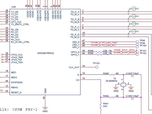
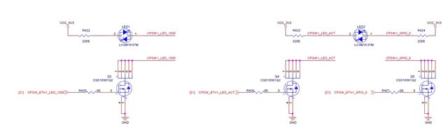
Our custom board uses the same reference design of Ethernet/LED HW as in attached custom board schematic.
1. There is no signal (100%) for CPSW_ETH1_LED_ACT (even we make network traffic by ping xxxx out/int) from the PHY.
2. CPSW_ETH1_LED_1000 is alway ON and blicking for both 100mbps/1000mbps setting (if set Ethernet Speed to 100bmps, it should be OFF as in user mannual).
May you advice to solve this issue? Thanks.
Part Number: AM3352
Tool/software:
Hi TI Experts,
Can you provide a List of E2Es that can be referred when starting a custom board hardware design?
Part Number: AM625
Tool/software:
SOC_UID is a device specific identifier calculated by ROM based on "KEK of the device which is unique to every single device, plus other ROM mata-data structure".
- unique per SoC and persistent
- available on HS-FS and HS-SE
- multiple usages: unique binding to enable JTAG unlock on HS-SE; unique serial number for SoC.
There are several ways to retrieve SOC_UID as listed
https://software-dl.ti.com/tisci/esd/latest/6_topic_user_guides/secure_debug.html#retrieveing-soc-uid
1/. ROM
- Reported by ROM from functional boot flow, i.e. peripheral boot modes like UART, USB-DFU
- JTAG in ROM WIR boot flow
2/. TIFS
- TISCI API
Part Number: AM625
Tool/software:
Hi,
I'm designing a DVH to be laid out by SVT and am working on the layout guidelines for them. I am trying to find the trace length matching requirements for certain components but can't seem to find them on any existing documentation. For reference, these are the components I need the trace length matching for: MIPI-CSI2, LPDDR4, OSPI Flash, Ethernet RGMII. Could you help me find these requirements? Thank you!
Best,
William
Part Number: SK-AM62B-P1
Tool/software:
Hello all,
This is a detailed guide on implementing an encrypted filesystem on an SK-AM62B-P1 using dm-crypt. Please note that similar steps with minimal changes should also work on other targets based on other SItara/Jacinto processors running TI SDK images.
Ready? Here are the steps you need!
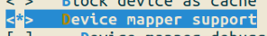
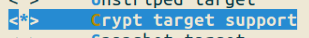
We will configure the device mapper framework and specifically the crypt target as a built-in module. The menuconfig snapshots below show the desired configurations.
These options are located at Menuconfig > Device Drivers > Multiple devices driver support (RAID and LVM)
Save config, exit and re-build the kernel.
We use busybox to generate the initramfs. The simplest way to do this to use the latest release from the downloads page and follow the build instructions with a cross-compiler documented here.
NOTE: Ensure that you use the right cross compiler here - else the image will not boot.
export CROSS_COMPILE=<path to aarch64 bin directory>
make CROSS_COMPILE=“$CROSS_COMPILE” defconfig
make CROSS_COMPILE=“$CROSS_COMPILE”
We will then install the busybox to a destination folder of our choice.
mkdir ../busybox_installdir
make CONFIG_PREFIX=../busybox_installdir install
At the very minimum, we need busybox, cryptsetup, mke2fs and dev nodes for our micro SD card partition. Let us do these one-by-one.
Other than the outputs of busybox (bin, sbin, usr), we need directories in the root of the initramfs like dev,etc,lib,proc,run,sys. We create these in an empty directory and the recursively copy the busybox installation to this folder.
cd <directory containing busybox source and installdir>
mkdir final_initramfs
cd final_initramfs
cp -r ../busybox_installdir .
mkdir etc lib opt proc sys dev home plainroot encroot tmp run
We choose to build cryptsetup dynamically here using bitbake. Once built, we copy the cryptsetup executable and its dependencies into our initramfs folder structure. This is a snapshot of the ldd output for the cryptsetup executable. These files can be copied to the final_initramfs folder from the TI SDK image outputs.

We use the mknod command to create the dev nodes we need.
NOTE: Doing this instead of udev reduces boot-time. You can choose to use udev as well.
sudo mknod urandom c 19
sudo mknod zero c 15
sudo mknod random c 1 8
sudo mknod null c 13
sudo mknod mmcblk1 b 179 96
sudo mknod mmcblk1p1 b 179 97
sudo mknod mmcblk1p2 b 179 98
sudo mknod mmcblk1p3 b 179 99
NOTE: We strictly need just the zero node and the mmcblk* nodes. The other nodes were created only for test purposes during the dev work.
We create a new file named init in the final_initramfs folder and add the following content in it. This is executed when the control passes to our initramfs.
#!/bin/sh

mount -t proc none /proc
mount -t sysfs none /sys
echo "Jumping to rootfs..."
sleep 1
#mount -o ro /dev/mmcblk1p2 /mnt
#umount /proc
#umount /sys
#exec switch_root /mnt /sbin/init
exec /bin/sh
Execute the below from the folder containing the initramfs.
find . -printo | cpio --null-ov --format=newc > initramfs.cpio
We can also compress the initramfs as a CPIO archive to reduce its size.
gzip ./initramfs.cpio
Create a new Yocto layer and then add the below code in a file named tisdk-base-image.bbappend. Place this file in a folder named recipes-core/images of the new Yocto layer.
NOTE: Provide the correct path to the initramfs.cpio.gz in the bbappend.
Navigate to the build folder of the Yocto setup and execute the below.
bitbake-layers create-layer ../sources/meta-<whatever you want>
bit bake-layers add-layer ../sources/meta-<whatever you want>
Navigate to your new layer and create a bbappend for the tisdk-base-image.
cd ../sources/meta-mylayer
mkdir recipes-core
mkdir recipes-core/images
cd recipes-core/images
vim tisdk-base-image.bbappend
Contents of the bbappend file should be as below.
INITRAMFS_IMAGE_NAME = "initramfs"
INITRAMFS_IMAGE_PATH = "/home/shashank/code/git/initramfs_busybox_test"
INITRAMFS_EXTENSION = "cpio.gz"

IMAGE_INSTALL:append = " cryptsetup"
IMAGE_INSTALL:remove = " resize-rootfs"

ROOTFS_POSTPROCESS_COMMAND += "add_initramfs_to_image; "

add_initramfs_to_image () {

    bbnote "Trying to add initramfs to the image now..."

    install -d ${IMAGE_ROOTFS}/boot

    install -m 0755 ${INITRAMFS_IMAGE_PATH}/${INITRAMFS_IMAGE_NAME}.${INITRAMFS_EXTENSION} ${IMAGE_ROOTFS}/boot/${INITRAMFS_IMAGE_NAME}.${INITRAMFS_EXTENSION}

    bbnote "Installed initramfs to the image..."

}

DEPENDS += " tisdk-tiny-initramfs"
MACHINE_FEATURES:remove = "efi"
WKS_FILE = "sdimage-3part.wks"
We also create a new folder called wic and create a new WIC kickstart file named sdimage-3part.wks that tells the build system that we need 3 partitions - boot, rootfs and a clone of rootfs.
mkdir wic
cd wic
vim sdimage-3part.wks
Contents of this file as below.
# short-description: Create SD card image with 3 partitions
# long-description: Creates a partitioned SD card image for TI platforms - one redundant partition for encrypted filesystem.
# Boot files are located in the first vfat partition with extra reserved space.

part /boot --source bootimg-partition --ondisk mmcblk0 --fstype=vfat --label boot --active --align 1024 --fixed-size 128 --use-uuid
part / --source rootfs --ondisk mmcblk1 --fstype=ext4 --label root --align 1024 --use-uuid
part --source rootfs --ondisk mmcblk1 --fstype=ext4 --label rootcopy --align 1024 --use-uuid
Use Balena Etcher or your favourite method to write the WIC image to the micro SD card. Plug in the card, power on the target and stop the execution at the U-Boot prompt.
While at the U-Boot prompt, we set the environment variables, copy the kernel image, device tree blob and the initramfs to designated addresses. Then we boot into the initramfs.
NOTE: Look for the print that we had put into the init script of the initramfs (“Jumping to roofs”) to confirm that we booted into the initramfs correctly.
setenv args_initramfs 'setenv bootargs console=${console} ${optargs}'
run args_all args_initramfs
load mmc 1:2 ${loadaddr} /boot/Image
load mmc 1:2 ${fdtaddr} /boot/dtb/ti/k3-am625-sk.dtb
load mmc 1:2 ${rdaddr} /boot/initramfs.cpio.gz
booti ${loadaddr} ${rdaddr}:0x${filesize} ${fdtaddr}
We will now do the usual crytpsetup stuff to convert the mmcblk1p3 partition into an encrypted partition. NOTE: The act of formatting the mmcblk1p3 as a LUKS volume and creating the EXT4 partition within it is a one-time step. For subsequent boots, it is sufficient to open, mount and then switch root.
cryptsetup luksFormat /dev/mmcblk1p3cryptsetup luksOpen /dev/mmcblk1p3 encrootcryptsetup -v status encrootcryptsetup luksDump /dev/mmcblk1p3dd if=/dev/zero of=/dev/mapper/encroot bs=1M/usr/bin/mke2fs -t ext4 /dev/mapper/encrootmount /dev/mapper/encroot /encrootmount /dev/mmcblk1p2 /plainrootcp -r /plainroot/* /encrootcd encroot/exec switch_root . sbin/initOnce the switch root has executed, you should see prints from your filesystem. Execute df -H to confirm that the filesystem is mounted at /dev/mapper/<xyz>.
Part Number: TMUX1308-Q1
Tool/software:
Hi Team,
TMUX1308 EN and control A0..A2 is being controlled by AM625 Sitara SOC.
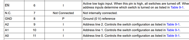
SOC IO buffers are off during power-up. The IOs are in high impedance and expected to take 1..2 seconds to be initialized to a known state.
Do you have any recommendation of connecting the EN and the control inputs during this period.
Are the TMUX EN and address control inputs A0..2 tolerant to being open for some time ( 1..2 sec) during power cycle until the SOC IOs are initialized.
Thank you for the support.
Regards,
Sreenivasa
Part Number: TMS320C6657
Tool/software:
How to re-build the Nor writer code of processor SDK 6.3 ?
Part Number: AM62A7
Tool/software:
Hi Expert,
Could you help to provide Pinmux excel file for AM62A?
SysConfig Tool export csv file does not list MUX Mode.
TDAV4VM provides MUX Mode
Thanks
Daniel
