Part Number: AM625


Hi everybody ,
customer would like to have Jtag connections/capabilities on their production board .
I suggested to copy SK-AM62 but here are questions :
- do you need to implement just page 29 ( so jtag connector ) ? coudl you avoid onboard clock buffer ( to save money ) ?
- is page 28 ( all buffers ) needed at all ?
- do you need if using 5V from PC the do we must pull USB_VBUS pin to 1.8V?
please consider they are going to use XDS110 on their production board
I also suggested schematics as on web here https://dev.ti.com/tirex/explore/node?node=AOi9Jj0vmBMJ0KQKaKITgg__FUz-xrs__LATEST
but not 100% crystla clean what to do
thank you very much
BR
Carlo
PS here you have page 28 & 29 of SK-AM62 schematics I m referring to ( page 28 is the one w the buffers )
Part Number: AM625
We are facing problem when connecting a SPI Nor (W25Q128VEIQ) to OSPI CS0.
Basically it is working but from time to time it comes to errors during SF PROBE command in u.boot.
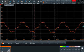
Please find attached the CLK Signal measured during sf probe.
Do you have any advice why the CLK Singal has this strange shape?
The CLK is running at 83.3Mhz
Many thanks and best regards
Stephan
Part Number: SK-AM62
Part Number: AM6412
Hi TI,
I can generate USB compliance test patterns on AM64 SoC by the following command
# devmem2 0x0f410480 w 0xA0
# devmem2 0x0f410080 w 0x4
# devmem2 0x0f410484 w 0x40000000
However, the test pattern stops transferring before the GL852GT USB 2.0 HUB.
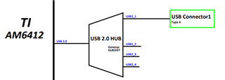
I want to measure the signal at the USB connector behind the USB 2.0 HUB.
They seem to be discarded by USB HUB.
Could I tell the USB 2.0 HUB to forward the signal to port 1 by specifying the destination (downstream port) for the test patterns?
How do I get USB compliance test patterns to pass through the USB 2.0 hub to USB connector 1?
Thanks,
Sean
Part Number: AM6412
Hi TI,
How to generate USB compliance test from CPU In Linux kernel 5.10 on AM64xx.
I followed the instructions below.
TDA4VM: USB 2.0 host test mode
Set dr_mode to host.
# cat /proc/device-tree/bus\@f4000/cdns-usb\@f900000/usb\@f400000/dr_mode
host
# cat /proc/device-tree/bus\@f4000/cdns-usb\@f900000/usb\@f400000/compatible
cdns,usb3
Unbind the usb 2.0 hub befind CPU.
# echo '1-1' > /sys/bus/usb/drivers/usb/unbind
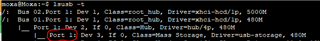
# lsusb -t
/: Bus 02.Port 1: Dev 1, Class=root_hub, Driver=xhci-hcd/1p, 5000M
/: Bus 01.Port 1: Dev 1, Class=root_hub, Driver=xhci-hcd/1p, 480M
And, type the command to generate the test pattern.
# echo compliance > /sys/kernel/debug/usb/xhci/xhci-hcd.1.auto/ports/port01/portsc
# cat /sys/kernel/debug/usb/xhci/xhci-hcd.1.auto/ports/port01/portsc
PORTSC = 0xc000e63
Powered Connected Enabled Link:U3 PortSpeed:3 Change: Wake: WDE WOE
However, The CPU doesn't seem to generate any signals.
What are we missing here?
Or, is there any other way to generate test patterns?
Thanks,
Sean
Part Number: SK-AM62
Hello.
i am working with linux arago default image for am62 evaluation board. I am trying to understand how reduce boot time, and get command prompt as fast as i can.
Just to have an idea of how to speed up this, i would like to avoid loading of hmi demo that is automatically loaded at startup. i have tryied the command
sudo systemctl disable hmi_demo
with no luck, can i have some hint?
Kind Regards
Emanuele Peruzzi
Part Number: TDA4VM
This document is intended to explain the interrupt registration process for R5F cores used in TI PDK
Part Number: PROCESSOR-SDK-AM64X
If you you are having trouble booting an AM64x or AM243x based board with Processor or MCU+ SDK v8.4, please see the below information.
With the production release of Silicon Release 2.0 (SR 2.0) of the AM64x/AM243x product families, the default device type is changing from General Purpose (GP) to High Security – Field Securable (HS-FS). HS-FS devices allow customers to enable security (for example, secure boot) if/when needed in their development flows. This change better prepares AM64x/AM243x based designs to easily enable security in a world of connected devices, growing threats, and developing standards. SR 1.0 devices, which were pre-production, are most likely GP devices. Therefore, existing SR 1.0 designs in development will need to change to SR 2.0 material to go to full volume production. This guide provides a short overview of this process and pointers to additional information. For more information about the differences between SR 1.0 and SR 2.0, please see the AM64x/AM243x Processor Silicon Revision 1.0, 2.0.
SR 1.0 GP devices and SR 2.0 HS-FS devices require different builds of the system firmware software component provided in AM64x/AM243x software packages (Software Development Kits). Software built for SR 1.0 GP devices will NOT boot on SR 2.0 HS-FS devices. The support for SR 2.0 HS-FS devices is added in the 8.4 version of the AM64x Software Development Kits (SDKs) and the AM243x MCU+ SDK. With this version, released at the end of September 2022, the system firmware can be built for both types of devices. Given their pre-production nature, support for SR 1.0 GP devices will be removed over time, and SR 2.0 HS-FS devices will be the only devices supported in the future.
Starting with v8.4, the SDKs provide board binaries for TI Evaluation Modules (EVMs) and Starter Kits (SKs), as well as the ability to build the proper device type support for custom builds on either TI boards or custom boards. The default images provided with this SDK will not boot on SR 1.0 devices without slight modifications. Those interested in evaluating SR 2.0 and HS-FS will need to migrate from previous versions of the SDKs to this new version or later. With support for both device types, evaluation can continue on SR 1.0 GP devices and preparations can be made to switch to production SR 2.0 HS-FS devices with minimal changes. These changes are covered in detail in the Processor SDK for Linux migration guide, the AM64x MCU+ SDK migration guide, or AM243x MCU+ SDK migration guide.
Since it is necessary to know the silicon revision of the device(s) for which software is being built, here is some information to help determine the revision number of the targeted board or device. At a high level, the orderable part number (OPN) for the devices change from ‘A’ to ‘B’, and this is reflected on the part markings on the top of the device. The SR 1.0 devices also included an ‘X’ at the start of the part numbers. For example, an XAM6442A marked part is SR 1.0, and an AM6442B marked part is SR 2.0. More information is included below.
Like the devices, the OPNs for the evaluation modules (EVMs and Starter Kits (SKs)) are changing to reflect the change to SR 2.0. The OPN for the AM64x Evaluation Module is changing from AM64GPEVM to AM64EVM (note the ‘GP’ is removed) for SR 1.0 to SR 2.0. The Starter Kit (SK) OPN is changing from SK-AM64 to SK-AM64B. The OPN is printed on the top side of the board with a white label and black text next to an ‘OPN’ silkscreen. If the OPN on the board is not available, the part symbolization information below can be used to identify the device type.
As indicated above, the OPNs are changing from SR 1.0 to SR 2.0 and this change will be reflected on the part symbolization on top of the device as well. For a custom board, this marking will be the most reliable way to identify the silicon revision of the device on the board. More information about the device symbolization can be found in the AM64x Sitara Processors datasheet and the AM243x Sitara Microcontrollers datasheet.
For reference, here is an example part symbolization for a SR 1.0 device:
+-------------------+  \T/ = TI LOGO
|                   |  SITARA = MARKET IDENTIFIER
| \T/      SITARA   |
|                   |
| XAM6442A          |  XAM6442A = PART NUMBER (Left Justified)
| SFGGAALV          |  SFGGAALV = ADD ON MARKING (Left)
| YMPLLLS           |
| YYY     @  G1     |   YM = YEAR MONTH DATE CODE
|                   |    P = SECONDARY SITE CODE FOR SCK
| O                 |  LLL = ASSEMBLY LOT CODE
\-------------------+    S = PRIMARY SITE CODE FOR SCK
  O - Pin 1            YYY = DEVICE IDENTIFIER
     (MARKED)            @ = 1 CHARACTER SUBSTRATE IDENTIFIER
                                   S - SEMCO
                                   D - DAEDUCK

                        G1 = ECAT; Must be symbolized with
                                   a solid underscore
A few things to note:
Here is an example part symbolization for a SR 2.0 device:
+-------------------+  \T/ = TI LOGO
|                   |  SITARA = MARKET IDENTIFIER
| \T/      SITARA   |
|     AM6442B       |  AM6442B  = PART NUMBER (Centered)
|     SEFHAALV      |  SEFHAALV = ADD ON MARKING (Centered)
|     YMPLLLS       |
|  YYY       G1     |   YM = YEAR MONTH DATE CODE
|                   |    P = SECONDARY SITE CODE FOR SCK
|                   |  LLL = ASSEMBLY LOT CODE
| O                 |    S = PRIMARY SITE CODE FOR SCK
\-------------------+  YYY = DEVICE IDENTIFIER
  O - Pin 1             G1 = ECAT; Must be symbolized with
     (MARKED)                      a solid underscore
A few things to note:
It is also possible to determine the device type with software and output from the console UART port. These steps are documented in the AM64x Processor SDK Security documentation.
Processor SDK for Linux migration guide
AM64x MCU+ SDK migration guide
AM243x MCU+ SDK migration guide
Part Number: 66AK2H12
Part Number: 66AK2H12
Hi,
How to re-build the PDK and SDK of PROCESSOR-SDK-RTOS-K2H for K2H?
