

In part 5 of this blog series, I discussed the construction of an input-isolated 2-wire sensor transmitter. Input-isolated 2-wire transmitters require isolating the sensor power and data signals from the 2-wire loop supply and 2-wire loop return (RTN). The main challenge when creating input-isolated or other complex 2-wire sensor transmitters is keeping the total current consumption from the loop to less than 4mA, a requirement I explained in part 3. One way to increase the available current in a 2-wire transmitter is to use a switching step-down DC/DC converter. The step-down converter must be optimized for low-output current applications so that it can operate at high-enough efficiencies to be useful in the system. Figure 1 is a simplified block diagram of such a system.
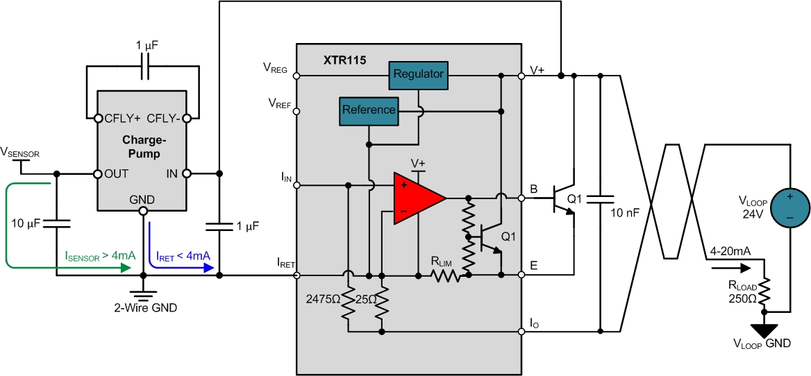
Figure 1: Simplified circuit of 2-wire sensor transmitter with step-down DC/DC converter to increase current available for the sensor
With a step-down power converter in the system, the maximum sensor current, ISENSOR, can be increased based on the converter efficiency, η, the output voltage, VOUT, the input voltage, VIN, and the maximum IRET current of 3.8mA, as defined in Equation 1:

Assuming an efficiency of 80%, an output voltage of 3.3V and an input voltage of 8V, the maximum sensor current can be increased to 7.36mA, an increase of almost 100% compared to the original maximum current of 3.8mA.
You must take special care when designing 2-wire transmitters with switching converters because the high-impedance loop power supply can negatively interact with the incremental-input impedance of the switching converter, causing loop stability and compliance issues (as explained in this DC/DC converter reference design. Therefore, isolated and nonisolated step-down converters for 2-wire transmitters are commonly designed with unregulated fixed-frequency charge pumps (such as the design shown in part 5 and explained in detail in these two reference designs:
1) Uniquely efficient isolated DC/DC converter for ultra-low power and low power applications reference design (TIDA-00349).
2) Isolated ultra-low power reference design for 4 to 20 mA loop-powered transmitters (TIDA-00167).
So to summarize, you can add switching step-down power converters to 2-wire 4-20mA sensor transmitters to increase the available sensor current. As I mentioned, you should construct the design carefully to verify that the operation of the step-down converter does not negatively interact with the input protection circuitry or impact the stability of the 4-20mA control loop.
This is the final post in the 2-wire transmitter series, but in future posts I’ll discuss 3- and 4-wire transmitters, expanding on this series as well as the information in fellow blogger Kevin Duke’s posts.
- Related TI Designs reference designs for 2-wire transmitters:
- Bridge Sensor Signal Conditioner with Current Loop Output, EMC Protection (TIPD126).
- Low Cost Loop-Powered 4-20mA Transmitter EMC/EMI Tested Reference Design (TIPD158).
- Isolated Loop Powered Thermocouple Transmitter Reference Design (TIDA-00189).
- See all the posts in our 2-wire transmitters series.
- Related TI Designs reference designs for 2-wire transmitters:
-
Related 3-wire blog posts from my colleague Kevin Duke:
-
-
See an overview of analog outputs and architectures.
-
Read about the evolution of 3-wire analog outputs.
-
Find commonly used analog design formulas in a new pocket reference by Art Kay and Tim Green
-
-

Benjamin Ko
-
Cancel
-
Up
0
Down
-
-
Reply
-
More
-
Cancel
Comment-

Benjamin Ko
-
Cancel
-
Up
0
Down
-
-
Reply
-
More
-
Cancel
Children