

Part 1:
2-wire 4-20 mA sensor transmitters are very common in industrial control and automation. They are popular because they allow a remote process to be monitored with only two analog signal wires. The two wires carry both the power for the sensor/monitoring circuitry and the analog output signal. Common applications for 2-wire sensor transmitters are pressure sensors, gas sensors, chemical sensors, level sensors, temperatures sensors, flow sensors, and many more.
Despite only having two wires, there are common issues to be aware of when designing these systems. This blog post provides an overview of 2-wire systems and how to avoid compliance voltage issues.
Overview
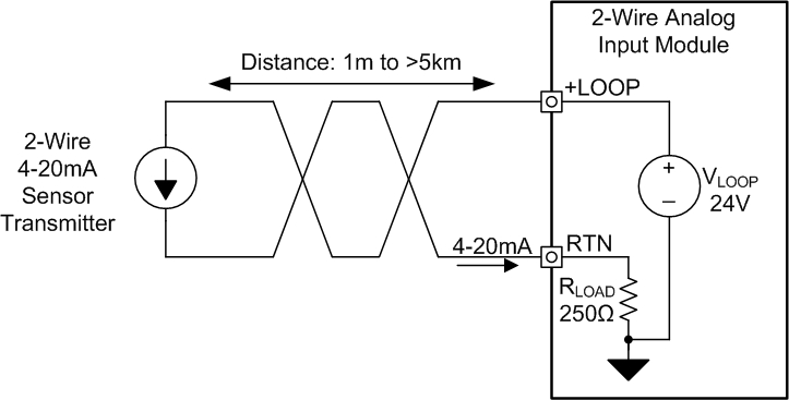
Figure 1 shows a 2-wire analog input module with two terminals: one for the loop power supply, VLOOP, and one for the 4-20 mA output of the 2-wire transmitter to return to, RTN. The 2-wire transmitter will precisely control the current it dissipates between 4 mA and 20 mA to provide control data back to the PLC input that describes the position, level, temperature and other measurement from the sensor. Common values for VLOOP and RLOAD are +24 V and 250 Ω.
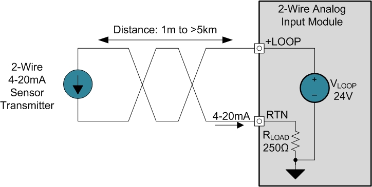
Figure 1: Simplified 2-wire 4-20mA transmitter
Texas Instruments provides several integrated circuits to make the design of 2-wire field transmitters easier. An example of a circuit utilizing the XTR116 is shown in Figure 2. Here, a resistive sensor is placed in a full resistive bridge. The output of the bridge is connected to an instrumentation amplifier, INA, which provides gain and level shifting of the sensor output. The INA output connects to the input of the XTR116 which then precisely controls the output current through the Q1 BJT to regulate the current between 4 mA and 20 mA. The XTR116 also integrates a +5 V linear regulator, VREG, and a 4.096 V precision reference, VREF. The VREG output is used to power the INA and the op amp circuitry internal to the XTR116. The VREF output provides a precise low-drift excitation voltage for the resistive bridge.
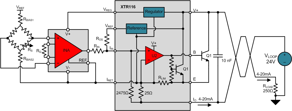
Figure 2: Example 2-wire sensor transmitter circuit
Compliance Voltage
The most common issue that people encounter when designing 2-wire field transmitter systems results from violating the compliance voltage of the system. The XTR116 has a minimum power-supply voltage, VCOMPLIANCE, of +7.5 V between V+ and IO for proper operation. If the resistive load and/or resistive losses due to cable length cause the supply voltage to decrease below +7.5 V, the system will lose its ability to regulate the output current.
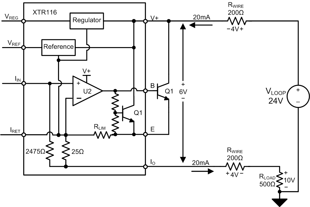
In Figure 3, an 18 V drop occurs in the current loop due to the 20 mA output current and the 900 Ω of series resistance in the loop. With a 24 V supply, this would only leave +6 V across the XTR116 which doesn’t meet the minimum supply voltage requirement of +7.5 V! As a result the output current will not reach 20 mA and will typically become non-linear as the input circuitry loses power.

Figure 3: Voltage compliance issue when using the XTR116
Voltage compliance issues are directly related to Ohm’s Law. The product of the output current and the resistance in the loop can’t exceed the supply voltage applied to the system. If VCOMPLIANCE, and VLOOP are known, the maximum loop resistance, RMAX, can be calculated as shown in Equation 1.

While voltage compliance issues can occur in the field due to long wiring distances, poor quality wires and multiple receivers, they also commonly occur in testing when the wrong value resistor is placed in the circuit for a load. If the output current of the transmitter stops increasing during testing, measure the voltage drop across the load. If the load voltage drop is higher than expected, the load resistance is likely the cause of the output current issue.
In my next blog post we’ll talk about grounding issues which are also very common in the design of 2-wire transmitters.
Related resources:
See more posts in our 2-wire transmitters series.
See 2-wire TI Design Precision references designs: TIPD 126 and TIPD 158.
Read an overview of industrial DACs analog outputs and architectures.
Learn more about the evolution of industrial DACs 3-wire analog outputs.
(Note: Click on images to enlarge.)
-

Patrick Dussud
-
Cancel
-
Vote Up
0
Vote Down
-
-
Sign in to reply
-
More
-
Cancel
Comment-

Patrick Dussud
-
Cancel
-
Vote Up
0
Vote Down
-
-
Sign in to reply
-
More
-
Cancel
Children