LMH34400DRLEVM: Issue of the designing TIA and comparator (Using LMH34400, TLV3601)

Part Number: LMH34400DRLEVM
Other Parts Discussed in Thread: TLV3601, LMH34400, OPA856

Tool/software:

Issues for TIA and Comparaot with LMH34400 and TLV3601.pptx

 This is Youngjoon Cho,  trying to develop a TIA and comparator circuit using the LMH34400 and TLV3601.

Our objective is to find a single peak in a highly reflected signal.

The TIA I built using the LMH34400 works fine, but when I connect the comparator I built using the TLV3601, there is an issue.

I have attached a document that summarizes the issue. 


Belows are specified summary

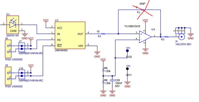
- Designing the TIA(LMH34400) and comparator(TVL3601) for measuring high reflective target

- We want to measure only single peak signal at the comparator

- TIA amplifies pulse signal well when it operates without connecting comparator

- However, there are DC offset, ringings and oscillation when comparator is cascaded, especially when the measured is signals are saturated (having long pulse width).

  • Hello Youngjoon Cho,

      I will be able to review this information in-depth by middle of this week. In the meantime, I talked to a co-worker who has worked on the LMH34400 to Interface to TLV3601 Comparator and TDC section of the datasheet in the lab and we were able to get it working by adding a 10Ohm isolation resistor directly at the output of the LMH34400. Attached is the schematic I was given:

    Thank you,
    Sima

  • Did the issue get resolved with the above ?

  • For the higher frequency noise, i directly measure the node without wires, then oscillation can be removed 

    LMH34400 TIA with TLV3601 comparator.pptx

    However, for the very large input current at the TIA circuit, there are relatively low frequency fluctuation(?) or  drift(?)

    I attached some simulation results for the circuit.

    (i used OPA856 for inverting amp with HPF at the each output port)

    I would like to know why this kind of fluctuation occurs and how to prevent it

    Thanks for your reply

  • Hello Youngjoon,

      Thank you for the update. 

      From our understanding, with a very large input current at the TIA, it will have ringing and DC offset at measurement point 1 and 2 if the comparator is on and with the HPF passive filter. But:

    1. With no HPF: good results
    2. With comparator in off state, but everything stays the same (with passive HPF filter) gives the best results
    3. With HPF, but no hysteresis for comparator there is no change 

      When it is said that comparator is in off state, is this with no connection (removing R3), or is this with no supplies provided to comparator, but the trace to comparator is still populated and present? 

       From slide 10, it seems like the issue is with large pulse width/duration rather than the amplitude of the input current since value of Vpp stays the same, is that correct? This means saturating the PD affects the width of the pulse, but TIA still sees the same input current range in each case? 

    Thank you,

    Sima 

  •  When it is said that comparator is in off state, is this with no connection (removing R3), or is this with no supplies provided to comparator, but the trace to comparator is still populated and present?  --> both of them, actually off supplied provided to comparator when i asked.

    For the high frequency noise, Using RF cables, i can remove it.

    it looks like that oscilloscope and proves can influence on the load effect.

    For the ringing noise, i makes a LPF at the output of TIA and adjusting

    then i can remove the ringing even the pulse width is a little bit widen 

    I changed R6,R7 from Kohms to 100~200ohm to match the input inpedance of plus and minus iuput stage of comparator.

    it can balance a DC offset of output of camparator as you can see the page 12.

    and i also changed R5 from 1Kohm to 100~200ohm

    it looks like that Its value effects on the speed(BW) and stability of comparator.

    if R5 is less than 10ohm, output will be oscillating, if R5 is larger than 1Kohm is can not make slope well within ns level.

    i adjusted the proper value to 200ohm for my application.

  • Hello Youngjoon,

      Thank you for sharing this update! I am glad you were able to find a working solution, that is really good to know about R5 (output resistor) affects on the comparator. 

    Best Regards,
    Sima